EP2045701A2 - Bildanzeigevorrichtung - Google Patents
Bildanzeigevorrichtung Download PDFInfo
- Publication number
- EP2045701A2 EP2045701A2 EP08017307A EP08017307A EP2045701A2 EP 2045701 A2 EP2045701 A2 EP 2045701A2 EP 08017307 A EP08017307 A EP 08017307A EP 08017307 A EP08017307 A EP 08017307A EP 2045701 A2 EP2045701 A2 EP 2045701A2
- Authority
- EP
- European Patent Office
- Prior art keywords
- substrate
- image
- display
- bending
- displayed
- Prior art date
- Legal status (The legal status is an assumption and is not a legal conclusion. Google has not performed a legal analysis and makes no representation as to the accuracy of the status listed.)
- Ceased
Links
Images















Classifications
-
- G—PHYSICS
- G06—COMPUTING OR CALCULATING; COUNTING
- G06F—ELECTRIC DIGITAL DATA PROCESSING
- G06F3/00—Input arrangements for transferring data to be processed into a form capable of being handled by the computer; Output arrangements for transferring data from processing unit to output unit, e.g. interface arrangements
- G06F3/002—Specific input/output arrangements not covered by G06F3/01 - G06F3/16
-
- G—PHYSICS
- G03—PHOTOGRAPHY; CINEMATOGRAPHY; ANALOGOUS TECHNIQUES USING WAVES OTHER THAN OPTICAL WAVES; ELECTROGRAPHY; HOLOGRAPHY
- G03G—ELECTROGRAPHY; ELECTROPHOTOGRAPHY; MAGNETOGRAPHY
- G03G15/00—Apparatus for electrographic processes using a charge pattern
- G03G15/50—Machine control of apparatus for electrographic processes using a charge pattern, e.g. regulating differents parts of the machine, multimode copiers, microprocessor control
- G03G15/5016—User-machine interface; Display panels; Control console
-
- G—PHYSICS
- G06—COMPUTING OR CALCULATING; COUNTING
- G06F—ELECTRIC DIGITAL DATA PROCESSING
- G06F3/00—Input arrangements for transferring data to be processed into a form capable of being handled by the computer; Output arrangements for transferring data from processing unit to output unit, e.g. interface arrangements
- G06F3/01—Input arrangements or combined input and output arrangements for interaction between user and computer
- G06F3/03—Arrangements for converting the position or the displacement of a member into a coded form
- G06F3/041—Digitisers, e.g. for touch screens or touch pads, characterised by the transducing means
- G06F3/0412—Digitisers structurally integrated in a display
-
- G—PHYSICS
- G06—COMPUTING OR CALCULATING; COUNTING
- G06F—ELECTRIC DIGITAL DATA PROCESSING
- G06F3/00—Input arrangements for transferring data to be processed into a form capable of being handled by the computer; Output arrangements for transferring data from processing unit to output unit, e.g. interface arrangements
- G06F3/01—Input arrangements or combined input and output arrangements for interaction between user and computer
- G06F3/048—Interaction techniques based on graphical user interfaces [GUI]
- G06F3/0484—Interaction techniques based on graphical user interfaces [GUI] for the control of specific functions or operations, e.g. selecting or manipulating an object, an image or a displayed text element, setting a parameter value or selecting a range
- G06F3/04845—Interaction techniques based on graphical user interfaces [GUI] for the control of specific functions or operations, e.g. selecting or manipulating an object, an image or a displayed text element, setting a parameter value or selecting a range for image manipulation, e.g. dragging, rotation, expansion or change of colour
-
- G—PHYSICS
- G06—COMPUTING OR CALCULATING; COUNTING
- G06F—ELECTRIC DIGITAL DATA PROCESSING
- G06F2203/00—Indexing scheme relating to G06F3/00 - G06F3/048
- G06F2203/048—Indexing scheme relating to G06F3/048
- G06F2203/04806—Zoom, i.e. interaction techniques or interactors for controlling the zooming operation
Definitions
- the present invention relates to an image display apparatus which displays an image.
- An apparatus such as a printer which records (prints) an image on a recording medium such as a printing paper is generally provided with a display (a display section) which is capable of displaying various information related to the image, and an operation panel which is operated by a user (refer to Japanese Patent Application Laid-open No. 2006-35662 for example).
- a display a display section
- an operation panel which is operated by a user
- the user operates various types of buttons provided on the operation panel, it is possible to carry out on display an image changing process such as a changing of a display image and an enlargement and a reduction of the image.
- An object of the present invention is to provide an image display apparatus in which it is possible to change easily an image which is to be displayed on the display even for a person who is not good at operating an equipment.
- an image display apparatus which displays an image, including a display which displays an image; an input mechanism which has a flexible and sheet shaped substrate, and a bending detection mechanism which is arranged on a surface of the substrate to detect a bending deformation of the substrate; and a display control mechanism which controls to change an image to be displayed on the display, based on the bending deformation of the substrate detected by the bending detection mechanism of the input mechanism.
- the bending deformation of the substrate is detected by the bending detection mechanism. Further, an image to be displayed on the display is changed by the display control mechanism. According to this arrangement, for changing the image to be displayed on the display, it is not necessary to carry out a plurality of operations of operation buttons provided on an apparatus main body, and even when the user is not good at operating an equipment, it is possible to change easily the image to be displayed on the display section.
- the display control mechanism may control the display to enlarge or reduce a displayed image which is currently displayed on the display.
- the display control mechanism may control the display section to enlarge the displayed image when the display control mechanism judges that the substrate is bent to form a projection upward, based on a detection result of the bending detection mechanism, and the display control mechanism may control the display section to reduce the displayed image when the display control mechanism judges that the substrate is bent to form a projection downward, based on a detection result of the bending detection mechanism.
- the display control mechanism enlarges the image displayed on the display.
- the display control mechanism reduces the image which is being displayed on the display section.
- the bending detection mechanism may have a plurality of bending detection sections arranged in a plurality of areas respectively, of the surface of the substrate, and when the bending deformation of the substrate is detected by one of the bending detection sections, the display control mechanism may control the display to enlarge or reduce the displayed image such that a portion, of the displayed image, corresponding to an area of the substrate arranged the one of the bending detection sections is to be a center of the enlargement or the reduction of the displayed image.
- the display control mechanism may control the display to display a image-list including a plurality of images at a time, and when the bending deformation of the substrate is detected by the bending detection mechanism, the display control mechanism may change the number of images in the image-list to be displayed on the display.
- the display control mechanism may change an image displayed on the display to another image different from the displayed image.
- the image display apparatus of the present invention may further include an image recording section which records an image on a recording medium; and an image control section which controls the image recording section to record an image displayed on the display on a recording medium.
- the recording control section when the recording control section judges that the bending deformation of the substrate detected by the bending deformation mechanism is of a type different from a bending deformation which changes the image to be displayed on the display, the recording control section may control the image recording section to record the displayed image on recording paper.
- the substrate may be formed of a rectangular sheet material, and when the recording control section judges that a corner portion of the rectangular substrate has been bent, based on the detection result of the bending detection section, the recording control section may control the image recording section to record the displayed image on a recording medium.
- the bending detection mechanism may have a plurality of the bending detection sections arranged on the plurality of areas respectively of the surface of the substrate.
- the plurality of bending detection sections are provided to the substrate, it is possible to detect distinctively each of the bending deformations in the plurality of areas of the substrate. Moreover, it is also possible to detect distinctively a deformation in a different direction of bending. Therefore, it is possible to make the display carry out the processes by allocating the plurality of image changing processes such as the changing of the image and the enlargement and the reduction of the image, for the bending deformation of various types which can be detected distinctively.
- the bending detection mechanism may have a piezoelectric layer provided on a surface of the substrate, and a first electrode and a second electrode which are arranged on a surface of the piezoelectric layer, and which are extended in parallel at an interval.
- the first electrode may include a plurality of first individual electrodes extending in one direction and being electrically conducted with each other
- the second electrode may include a plurality of second individual electrodes extending in the one direction and being electrically conducted with each other
- the first and second individual electrodes may be arranged alternately on the one surface of the piezoelectric layer.
- the second electrodes and the first electrodes extended in the same direction on one surface of the piezoelectric layer are arranged alternately, and a plurality of sets of electrodes including the first electrode and the second electrode, exists on one surface of the piezoelectric layer. Therefore, it is possible to detect by one bending detection section, the bending deformation of the substrate which occurs in the area having a certain width, while increasing an electrical load generated by the bending deformation of the substrate, and improving a detection sensitivity by shortening a distance between the first electrode and the second electrode .
- the bending detection mechanism may include a plurality of bending detection sections arranged on one surface of the substrate, and each of the bending detection sections may include the first electrode and the second electrode which are mutually parallel, and a direction of extension of the first and second electrodes may be different among the bending detection mechanisms.
- the direction of extension of the electrodes (the first electrodes and the second electrodes) is different between the bending detection sections, it is possible to detect distinctively each of the bending deformation of the substrate in different directions.
- the bending detection mechanism may have a piezoelectric layer provided on a surface of the substrate, and a first electrode arranged on one surface of the piezoelectric layer, and a second electrode arranged on the other surface of the piezoelectric layer.
- the bending detection mechanism may have an electrical resistor which is formed of an electroconductive material arranged on a surface of the substrate, and of which an electrical resistance changes depending on the bending deformation of the substrate.
- a principle of bending detection of the bending detection portion in the present invention is similar to a principle of measuring distortion of a distortion gauge.
- an electrical resistor provided on the surface of the substrate is elongated or contracted together with the substrate. Accordingly, an electrical resistance of the electrical resistor changes. Due to the change in the electrical resistance of the electrical resistor, it is possible to detect the bending deformation of the substrate.
- the bending detection mechanism may have a plurality of acceleration sensors arranged on a surface of the substrate.
- the acceleration sensors are provided on the substrate, it is possible to detect a change in a position of the substrate at a plurality of locations. Therefore, it is possible to detect the bending deformation of the substrate from a change in the position at the plurality of locations.
- the display as a whole may have a flexibility, and the display may be provided on the substrate, and may be deformable by bending integrally with the substrate.
- the display is deformable by bending integrally with the substrate, it is possible to change an image of the display section by deforming by bending the substrate positioned at a rear side of the display section while observing the image which is displayed on the display section.
- the display may be provided to be separated (isolated) from the substrate.
- the display when the display is provided to be separated (isolated) from the substrate, a structure of the input mechanism becomes simple. Moreover, unlike in the case in which the display is provided integrally with the substrate, the display is not particularly required to have flexibility, and it is not difficult to see the image due to the bending of the display section.
- the substrate may be provided with an posture identifying section which identifies a regular usage posture corresponding to an image displayed on the display.
- the display section and the substrate are separated, when the user has held the substrate of the input unit (input mechanism) in hand, sometimes it is not known as to whether, the current attitude (posture) of the substrate is a regular attitude corresponding to the image of the display section.
- the identifying section for identifying the regular usage attitude is provided to the substrate, the user, at the time of operating the substrate, is capable of identifying immediately as to by bending the substrate in which posture, it is possible to carry out correctly the image change of the display section.
- the posture identifying section it may be a mark or a display provided on the substrate, it may be identified by a shape of the substrate (for example, when there is a handle which makes it easy for the user to hold).
- the image display apparatus of the present invention may further include a posture detecting section which detects a posture of the substrate.
- the posture detecting section may detect the posture of the substrate based on a detection result of the bending detection mechanism.
- the posture detecting section identifies the current posture of the substrate based on the type of bending deformation of the substrate which is detected by the bending detection mechanism. Consequently, a special type of sensor for detecting the posture of the substrate is unnecessary.
- an image display apparatus which displays an image, including a substrate in a form of a flexible sheet; a display which displays an image, which is flexible, and which is provided integrally to the substrate; a bending detection mechanism which is arranged on a surface of the substrate, and which detects a bending deformation of the substrate; and a display control mechanism which controls the display to change an image to be displayed on the display, based on the bending deformation of the substrate which is detected by the bending detection mechanism.
- the bending deformation of the substrate is detected by the bending detection section, and further, an image to be displayed on the display section which is provided integrally with the substrate is changed by the display control mechanism.
- the display control mechanism for changing the image to be displayed on the display section, it is not necessary to carry out a plurality of operations of operation buttons, and even when the user is not good at operating an equipment, it is possible to change easily the image to be displayed on the display section.
- the display section is provided integrally with the substrate, it is possible to change the image of the display section by causing the substrate to be deformed by bending, which is positioned at a rear side of the display section.
- the present invention it is possible to change the image to be displayed on the display section only by causing the substrate of the input mechanism to be deformed by bending. Consequently, it is not necessary to carry out a plurality of operations of operation buttons provided on an apparatus main body, and even when the user is not good at operating an equipment, it is possible to change easily the image to be displayed on the display section.
- Fig. 1 is a perspective view of a printer of the first embodiment
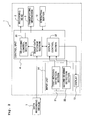
- Fig. 2 is a block diagram showing schematically an electrical structure of the printer.
- a printer 1 (image display apparatus) of the first embodiment includes a recording head 2 (image recording section) which records an image on a printing paper P (recording medium), a transporting mechanism 3 which transports the printing paper P in a predetermined direction (frontward direction in Fig. 1 ), and a control unit 4 which controls various mechanism of the printer 1 including the recording head 2 and the transporting mechanism 3.
- a recording head 2 image recording section
- a transporting mechanism 3 which transports the printing paper P in a predetermined direction (frontward direction in Fig. 1 )
- a control unit 4 which controls various mechanism of the printer 1 including the recording head 2 and the transporting mechanism 3.
- the printer 1 has a printer-body 6 having a substantially rectangular parallelepiped shape, and the recording head 2, the transporting mechanism 3, and the control unit 4 are accommodated inside the printer-body 6.
- the recording head 2 a head which carries out printing on the printing paper P by a known method such as a head of an ink-jet type, a laser type, or a thermal transferring type is used.
- the data recording medium 7 in which image data is recorded (refer to Fig. 2 ) is connected to the printer 1, the recording head 2 records on the printing paper P an image of the image data (image file) which is input from a data recording medium 7, based on a command from the control unit 4.
- one image data (image file) means a set of integrated data which forms one image.
- a part of a lower-half portion of the printer-body 6 is open frontward.
- a paper feeding tray 9 in which the printing papers P are accommodated, and paper discharge tray 8 to which the printing papers P with an image recorded thereon are discharged are provided in the open portion.
- the transporting mechanism 3 drives transporting rollers, which are rotated by a motor, to transport the recording paper P on the paper feeding tray 9 to the recording head 2 in the printer-body, and to discharge the printing paper P having an image recorded thereon by the recording head 2 to the paper discharge tray 8 at the front.
- a cartridge mounting portion 10 is provided on a front surface of the lower-half portion of the printer-body 6 at a side of the paper feeding tray 9 and the paper discharge tray 8.
- An upper portion of the printer-body 6 is inclined frontward, toward a user who is at a frontward side of the paper surface in Fig. 1 .
- a plurality of operation buttons 12 which are operated by the user are provided on an inclined surface 6a.
- the printer 1 includes an input unit (input mechanism) having a flexible substrate 20 in the form of a sheet, and two bending detection sections 21 and 22 (bending detection mechanism) which are arranged on a surface of the substrate 20, and which detects bending deformation of the substrate 20.
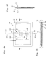
- Fig. 3A is a plan view of the input unit 14, and Fig. 3B is a cross-sectional view taken along a line IIIB-IIIB in Fig. 3A .
- the surface of the substrate 20 of the input unit 14 is provided with a display 13 (display section) having flexibility as a whole, and the display 13 is deformable by bending integrally with the substrate 20.
- a so-called electronic paper having a thickness of a paper of one by several tenths of millimeter, and on which data is erasable and displayable by applying a voltage etc. can be cited as an example of such display 13.
- the input unit 14 and the display 13 are connected to the control unit 4 stored (accommodated) inside the printer-body 6 (refer to Fig. 2 ), via a cable 15.
- the substrate 20 of the input unit 14 is operated as bending a paper by the user.
- a bending deformation developed in the substrate 20 is detected by the two bending detection sections 21 and 22 provided to the substrate 20.
- the control unit 4 changes an image to be displayed on the display 13 based on a mode of the bending deformation of the substrate 20 detected by the bending detection sections 21 and 22.
- the substrate 20 is formed to be rectangular shaped in a plan view.
- the flexible substrate 20 it is possible to use a resin sheet material made of a synthetic resin material such as polyimide, or a thin plate made of a metallic material such as an aluminum alloy and stainless steel. Note that in the description a direction parallel to a longer side of the rectangular shaped substrate is called as “a longitudinal direction", and a direction parallel to a shorter side, that is , orthogonal to the longitudinal direction is called as "a short-side direction”.
- the two bending detection sections are provided on a rear surface (a surface on opposite side of the display 13, that is, a surface on a rearward side of the paper surface in Fig. 3 ).
- the first bending detection section 21 and the second bending detection section 22 are arranged side by side in a direction of short side (in a vertically direction in Fig. 3A ), at a central portion in a longitudinal direction (left-right direction in Fig. 3A ) of the substrate 20.
- a detector in which an electromechanical conversion effect(a mechanical distortion is converted to an electric signal) has been used is adopted in the first embodiment.
- each of the first bending detection section 21 and the second bending detection section 22 has a piezoelectric layer 23 formed on a rear surface of the substrate, and two types of electrodes (a first electrode 24 and a second electrode 25) which are formed on a surface (a rear surface) of the piezoelectric layer 23, on an opposite side of the substrate 20, and extended in parallel with a gap mutually.
- the piezoelectric layer 23 is made of a piezoelectric material which is principally composed of lead zirconate titanate (PZT), which is a solid solution of lead titanate and lead zirconate, and which is a ferroelectric substance, and is formed to cover the rear surface of the substrate 20 entirely.
- PZT lead zirconate titanate
- the piezoelectric layer 23 is formed on the substrate by a method such as an aerosol deposition method, a sputtering method, and a sol-gel method.
- first electrodes 24 in the comb teeth form which are extended parallel along one direction, and which are in mutual conduction
- second electrodes 25 in the same comb teeth form which are extended parallel to the first electrodes 24, and which are in mutual conduction.
- first electrodes 24 and the second electrodes 25 are arranged alternately.
- the first electrodes 24 and the second electrodes 25 are formed of an electroconductive material such as gold, copper, silver, palladium, platinum, or titanium, by using a method such as a screen printing method and a vapor deposition method.
- a direction of extension of the electrodes differ mutually for the first bending detection section 21 and the second bending detection section 22. More concretely, a direction of extension of the electrodes of the first bending detection section 21, arranged at a position somewhat on upper side (upward) of a central portion of the substrate 20 is parallel to the longitudinal direction of the rectangular substrate 20. On the other hand, a direction of extension of the electrodes of the second bending detection section 22, arranged at a position somewhat on a lower side (downward) of a central portion of the substrate 20 is parallel to a short side direction of the substrate 20. In other words, the direction of extension of the electrodes of the first bending detection section 21 and the direction of extension of the electrodes of the second bending detection section 22 are mutually orthogonal.
- a low electric potential such as 0 V (ground electric potential)
- a high electric potential such as 50 V
- a portion of the piezoelectric layer 23 between the first electrode 24 and the second electrode 25 is polarized in a direction from the second electrode 25 to the first electrode 24.
- a wire 27 and a wire 28 are drawn respectively from the plurality of first electrodes 24 which are brought into mutual conduction of the first bending detection section 21 and the second bending detections section 22, and these two wires 27 and 28 for the two first electrodes 24 are connected to the control unit 4 (refer to Fig. 2 ).
- the plurality of second electrodes 25 of the first bending detection section 21 and the plurality of second electrodes 25 of the second bending detection section 22 are connected to a common wire 29.
- the common wire 29 is connected to a ground wire provided toward the control unit 4, and all the second electrodes 25 are kept at the ground electric potential all the time via the common wire 29.
- an insulating layer 26 is formed on the rear surface of the piezoelectric layer 23, to cover all the first electrodes 24 and the second electrodes 25 of the first bending detection section 21 and the second bending detection section 22. It is possible to form the insulating layer 26 by a synthetic resin material having an insulating property, such as polyimide. In this manner, since the first electrodes 24 and the second electrodes 25 are covered by the insulating layer 26, it is possible to avoid occurrence of problems such as an exfoliation and a damage of the electrode, and a short circuit between the first electrode 24 and the second electrode 25.
- Figs. 4A to 7C show that an electric potential of the first electrode is a positive electric potential
- '-' shows that an electric potential of the first electrode is a negative electric potential
- 'GND' shows that an electric potential of the electrode (the first electrode 24 or the second electrode 25) is the ground electric potential.
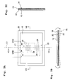
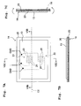
- Fig. 4A shows a plan view of the input unit 4
- Fig. 4B show a cross-sectional view along a line IVB-IVB
- FIGS. 5A to 7A, Figs. 5B to 7B , and Figs. 5C to 7C are similar to Figs 4A, 4B and 4C , respectively.
- the piezoelectric layer 23 is deformed along with the substrate 20, to form a projection toward a front ward side (upward) or a rearward side (downward).
- a portion on a lower surface of the piezoelectric layer 23, between the first electrode 24 and the second electrode 25 is elongated or contracted along a direction (longitudinal direction of the substrate 20) orthogonal to the direction of extension of electrode.
- an electric field in a direction opposite to the direction of polarization (in other words, an electric field in a direction from the first electrode 24 toward the second electrode 25) is generated at an interior of the piezoelectric layer 23, and as a result of this, a positive electric potential (+) higher than the electric potential of the second electrode 25 (ground electric potential) is generated in the first electrode 24.
- a deformation (elongation or contraction) occurs in a portion of the piezoelectric layer 23 sandwiched between the first electrode 24 and the second electrode 25.
- a direction of the deformation is parallel to the direction of extension of the electrode (longitudinal direction of the substrate 20), and is a direction different from (orthogonal to) the direction of polarization of the piezoelectric layer 23 in the first bending detection section 21. Therefore, in the another first bending detection section 21, almost no electric potential difference is generated between the first electrode 24 and the second electrode 25.
- the direction of extension of the first electrode 24 and the second electrode 25 differs mutually (is orthogonal) between the first bending detection section 21 and the second bending detection section 22 provided to the substrate 20, it is possible to detect distinctly the bending deformation of the substrate 20 around the two axes namely the axis C1 and the axis C2 mutually orthogonal by the first bending detection section 21 and the second bending detection section 22.
- each of the first bending detection section 21 and the second bending detection section 22 doesn't have the plurality of first electrodes 24 and the plurality of second electrodes 25 arranged alternately, but have one each of the mutually parallel first electrode 24 and the second electrode 25, and when it is possible to detect accurately at the control unit 4, a change in the electric potential of the first electrode 24 when the piezoelectric layer 23 between the set of the first electrode 24 and the second electrode 25 has deformed, it is possible to detect the bending deformation of the substrate 20.
- the change in the electric potential of the first electrode 24 is small, it is difficult to detect correctly the change in the electric potential, and there is a fear of misdetection.
- the plurality of first electrodes 24 and the plurality of second electrodes 25 extended in the same direction are arranged alternately on the same surface of the piezoelectric layer 23 in each of the first bending detection section 21 and the second bending detection section 22, there exists a plurality of sets of electrodes including the first electrode 24 and the second electrode 25. Therefore, it is possible to detect the bending deformation of the substrate 20 occurred in an area having a certain width (dimension) by one bending detection section. In addition, it is possible to improve the detection sensitivity because the distance between the first electrode 24 and the second electrode 25 can be shortened. Moreover, as there exists a plurality of sets of electrodes including the first electrode 24 and the second electrode 25, it is possible to increase an amount of electric load generated due to the bending deformation of the substrate 20, and the detection sensitivity is improved.
- the piezoelectric layer 23 is arranged on the surface of the substrate 20, on the opposite side of the display 13.
- the piezoelectric layer 23 and the display 13 are arranged on opposite sides sandwiching the substrate 20.
- a distance from an indifferent line of bending of the three-layered structure up to the lower surface of the piezoelectric layer 23 increases. Therefore, since the distortion developed in the lower surface of the piezoelectric layer 23 when the substrate 20 is bent increases, and the electric potential generated in the first electrode 24 becomes high, it becomes easy to detect the bending deformation of the substrate 20.
- control unit 4 is capable of identifying distinctly a mode of the plurality of bending deformations occurring in the substrate 20, based on a voltage signal (electric potential of the first electrode 24) which is output from each of the first bending detection section 21 and the second bending detection section 22.
- the printer 1 of the first embodiment when the substrate 20 of the input unit 14 is bend in a predetermined mode set in advance as bending a paper, the bending deformation occurred in the substrate 20 is detected by the first bending detection section 21 and the second bending detection section 22. Then an image to be displayed on the display 13 is changed according to the bending deformation which is detected (image changing process).
- image changing process A concrete content of the image changing process will be described in detail in the following description of the control unit 4.
- the control unit 4 includes a Central Processing Unit (CPU), a Read Only Memory (ROM) in which computer programs and data etc. for controlling various mechanisms of the printer are stored, a Random Access Memory (RAM) which temporarily stores data to be processed by the CPU, and an input-output interface which inputs and outputs signals between the printer 1 and an external apparatus (unit) .
- CPU Central Processing Unit
- ROM Read Only Memory
- RAM Random Access Memory
- the control unit 4 includes a recording control section 30 (recording control mechanism), an image-data storage section 31 in which image data input from the data recording medium 7 is stored, and a display control section 32 (display control mechanism) which controls the display 13.
- a plurality of image data ordered in advance, based on certain conditions such as names of data files (for example, in alphabetic order), and time and date of creating of image data (time-stamp information) is recorded in image folders.
- the data recording medium 7 is connected to the printer 1, the plurality of image data which is read out from the data recording medium is stored in the image-data storage section 31.
- the data recording medium 7 in which the image data is stored a storage device such as a USB memory and a memory card which is to be plugged into a slot of the printer, or an external storage device (unit) to be connected to the control unit 4 by a cable or by a wireless connection is appropriate.
- the data which is recorded in the data recording medium 7 may not be only a still image data which is taken by a digital camera, and may be also a video data (movie data) which is shot by a digital video camera.
- the video data is a set of a plurality of still image data which is continued time wise, and when this video data is input from the data recording medium 7, in the control unit 4, the plurality of still image data is extracted from the video data, and a part of (some of) the plurality of still image data is displayed on the display 13, or, a still image is recorded on the printing paper P.
- the recording control section 30 controls the recording head 2 and the transporting mechanism 3 to print on the printing paper P, an image of image data selected by a user, upon referring to the data recorded in the image-data storage section 31.
- the display control section 32 controls the display 13 to display the information regarding a state of the printer 1 ("now printing” or "a standby state"), an error message or the like, to notify the users of the information.
- the display control section 32 has a function of changing an image to be displayed on the display 13 according to the mode of the bending deformation of the substrate 20, which is detected by the first bending detection section 21 and the second bending detection section 22, when the substrate 20 of the input unit 14 is bent by the user.
- "Changing an image to be displayed on the display 13" indicates changing a part of the image or the entire image to be displayed on an entire screen of the display 13. Consequently, this includes as a matter of course, switching (changing) an image of certain image data which is displayed currently to an image of another image data, as well as carrying out an image processing such as an enlargement and reduction (zooming in and zooming out) of the image which is displayed currently.
- the recording control section 30, the image-data storage section 31, and the display control section 32 are realized by the CPU, the ROM, and the RAM etc. forming the control unit 4.
- various computer programs such as a computer program for controlling the recording head 2 and the transporting mechanism 3 and a computer program for controlling the image to be displayed on the display 13 are stored in the ROM of the control unit 4.
- the computer programs stored in the ROM are executed by the CPU of the control unit 4, a function of each of the recording control section 30, the image-data storage section 31, and the display control section 32 is realized.
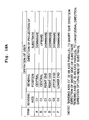
- the printer 1 of the first embodiment is capable of detecting distinctly, the mode of the plurality of bending deformation developed in the substrate 20 when the substrate 20 is subjected to the bending operation by the user, because the first bending detection section 21 and the second bending detection section 22 are provided to the substrate 20. Therefore, as shown in Figs. 8A and 8B , six types of image changing process regarding the enlargement and reduction of the image, and the switching of the image are assigned to six types of bending deformations (items A to F), respectively, the six types of bending deformations being detected distinctly by the first bending detection section 21 and the second bending detection section 22.
- the display control section 32 makes a judgment that the substrate 20 is bent to form a projection downward, around the axis C1, and the display control section 32 displays on the display 13 a contracted image in which the displayed image is made further smaller.
- the display control section 32 Upon receiving this signal, the display control section 32 makes a judgment that the substrate 20 is bent to form a projection upward, around the axis C1, and the display control section 32 displays on the display 13 an enlarged image in which a central portion of the image being displayed currently is enlarged.
- the display control section 32 zooms out the image displayed on the display 13.
- the display control section 32 enlarges the image displayed on the display 13.
- a weak electric field in the direction opposite to the direction of polarization of the piezoelectric layer 23 is generated in an area, of the first bending detection section 21, between the first electrode 24 and the second electrode 25, and a comparatively small positive electric potential having an absolute value not higher than a predetermined value is generated in the first electrode 24 of the first bending detection section 21.
- the display control section 32 Upon receiving this signal, the display control section 32 makes a judgment that the substrate 20 is bent to form a projection downward at a slow speed, around the axis C1. Moreover, the display control section 32 selects an image data subsequent to the image data which is currently displayed on the display 13, among the plurality of the ordered image data stored in the image-data storage section 31, and switches the image to be displayed on the display 13 to the image of the selected image data.
- a weak electric field in the direction same as the direction of polarization of the piezoelectric layer 23 (direction from the second electrode 25 toward the first electrode 24) is generated in an area, of the first bending detection section 21, between the first electrode 24 and the second electrode 25, and a comparatively small negative electric potential having an absolute value not higher than a predetermined value is generated in the first electrode 24 of the first bending detection section 21.
- the display control section 32 Upon receiving this signal, the display control section 32 makes a judgment that the substrate 20 is bent to form a projection upward at a slow speed, around the axis C2. At this time, the display control section 32 selects image data previous to image data which is currently displayed on the display 13, among the plurality of the sorted image data stored in the image-data storage section 31, and switches the image to be displayed on the display 13 to an image of the selected image data.
- the display control section 32 has made a judgment that the substrate 20 has been bent to form a projection downward at a considerably (substantially) high speed, the display control section 32 switches the image to be displayed on the display 13 to an image after five images of the image being currently displayed. Conversely, when the display control section 32 has made a judgment that the substrate 20 has been bent to form a projection upward at a considerably (substantially) high speed, the display image control section 32 switches the image to be displayed on the display 13 to an image before five image of the image being currently displayed.
- the user when the user is aware that the displayed image is substantially far sequentially from the desired image to be displayed, the user is capable of forwarding or returning five images at a time such that the image to be displayed on the display 13 becomes closer to the desired image in a short time, by bending the substrate 20 at a high speed. Thereafter, as the displayed image comes closer to the desired image, then it is possible to forward or return one image at a time while checking whether the image displayed is the desired image, by bending the substrate 20 at a slow speed.
- the number of images skipped at once in the high-speed bending operation as described above is not limited to five and may be determined arbitrary.
- the recording control section 30 controls the recording head 2 and the transporting mechanism 3 to record the image displayed currently on the display 13 on the printing paper P.
- the printer 1 of the first embodiment described above the following effect is achieved.
- the bending deformation of the substrate 20 is detected by the first bending detection section 21 and the second bending detection section 22, and further, based on the detected bending deformation, the image to be displayed on the display 13 is changed by the display control section 32.
- the display control section 32 it is possible to carry out enlargement and reduction of image and switching (changing) of image (forwarding / returning) only by a simple operation of bending the substrate 20. Consequently, for changing the image to be displayed on the display 13, complication operation of the operation buttons 12 is not necessary, a user who is not good at operation of equipment is capable of changing easily the image to be displayed on the display 13.
- the display 13 as a whole has flexibility, and furthermore, the display 13 is provided integrally to the substrate 20, to be deformable by bending. Therefore, the user is able to change the image to be displayed on the display 13 by deforming by bending the substrate 20 positioned at a rear side of the display 13, while looking at the image being displayed on the display 13.
- a structure and a position of the bending detection section which detects the bending deformation of the substrate, and the number of bending detection sections is restricted to those described in the first embodiment, and it is possible to make the following changes.
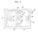
- five bending detection sections 41 to 45 may be provided at five locations namely, a central portions of the substrate 20, and four sides around the central portion of the substrate 20.
- the direction of extension of the first electrode 24 and the second electrode 25 are parallel to the short-side direction of the substrate 20.
- the direction of extension of the first electrode 24 and the second electrode 25 are parallel to the longitudinal direction of the substrate 20.
- independent wires are drawn from the first electrodes 24 of the five bending detection sections 41 to 45, whereas, a common wire 29 is drawn from the second electrodes 25 of the five bending detection sections 41 to 45.
- a bending deformation of the substrate 20 around an axis parallel to the short-side direction of the substrate is detected by the three bending detections sections 41 to 43 arranged at the central portion in the vertical direction of the substrate 20, and a bending deformation of the substrate 20 around an axis parallel to the longitudinal direction of the substrate is detected by the two bending detections sections 44 and 45 arranged at upper and lower position.
- each of the five bending detection sections 41 to 45 are arranged in different area on the surface of the substrate 20, it is possible to detect the bending deformation occurred locally in a part of the substrate 20 when only the part of the substrate 20 is bent by the user. For example, when a right end portion of the substrate 20 is bend around the axis parallel to the short-side direction of the substrate 20, the bending detection occurred locally in this right end portion is detected by the bending detection section 42 at a right side. In this manner, it is possible to detect not only a bending direction but also a bending position when the substrate is bent locally. In other words, as compared to the abovementioned first embodiment, since it is possible to detect more distinctly the mode of the bending deformation of the substrate 20, it is possible to allocate a multiple number of processes for the mode of bending deformation which is detected distinctly.
- Fig. 10A the 'bending position' indicates a position at which the substrate 20 is bent by the user.
- the display control section 32 enlarges or reduces an image displayed on the display 13, with a portion of the substrate 20 corresponding to an area in which the bending detection sections 41 to 45 which detect the bending deformation of the substrate 20 are arranged, as a center.
- the display control section 32 upon receiving signals output from the bending detection sections 41 to 45, is capable of identifying that the right end portion of the substrate 20 has been bent locally to form a projection downward.
- the display control section 32 controls the display 13 to display an enlarged image which has been enlarged with the right end portion of the image as a center.
- the right end portion of the image corresponds to an area in which the bending detection section 42 is arranged.
- the display control section 32 changes a position of enlargement (a center of the enlargement) to the right end portion (in other words, changes the display image on the display 13 to an image in which the right end portion is enlarged).
- the display control section 32 upon receiving signals output from the bending detection sections 41 to 45, is capable of identifying that the right end portion of the substrate 20 has been bent locally to form a projection upward. At this time, the display control section 32 displays on the display 31 an image which has been reduced with the right end portion of the image as a center, corresponding to the area in which the bending detection section 42 is arranged.
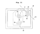
- a bending detection section (third bending detection section 46) may be provided in an area at an upper-right corner portion of the rectangular shaped substrate 20, and a bending deformation of the upper-right corner portion of the substrate 20 may be detected by the third bending detection section 46.
- the direction of extension of the first electrode 24 and the second electrode 25 of the third bending detection section 46 is a direction inclined at 45° in a clockwise direction with respect to the longitudinal direction of the substrate 20 (direction of extension of electrodes of the first bending detection section 21), and 45° in a counterclockwise direction with respect to the short-side direction of the substrate 20 (direction of extension of electrodes of the second bending detection section 22).
- a wire independent of the first bending detection section 21 and the second bending detection section 22 is drawn from the first electrode 24 of the third bending detections section 46.
- the second electrode 25 of the third bending detection section 46 is connected to the wire 29 in common to the second electrode 25 of the first bending detection section 21 and the second bending detection section 22.
- the display control section 32 is capable of identifying that the upper-right portion of the substrate 20 has been bent.
- the bending deformation of the upper-right corner portion of the substrate 20 which is detected by the third bending detection section 46 is assumed to be a deformation of a mode different from the bending deformation for changing the image to be displayed on the display 13. Therefore, a process different from the image changing process described above can be allocated for this bending deformation of the upper-right corner portion.
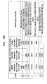
- Figs. 12A and 12B since the image changing process from items A to F is similar to the image changing process in Figs. 8A and 8B of the first embodiment, the description thereof is omitted.
- item G in Figs. 12A and 12B when the upper-right corner portion of the substrate 20 is bent to form a projection downward (rearward side) around an axis C3 and the first electrode 24 of the third bending detection section 46 is at the positive electric potential, a judgment is made that the bending deformation occurred in the substrate 20 is not a bending deformation aiming for changing the image to be displayed on the display 13, but is a bending deformation aiming for image recording.
- the recording control section 30 controls the recording head 2 to record the displayed image on the printing paper P. Moreover, as it has been described above, after an instruction for recording the image is made, as shown in item H in Figs. 12A and 12B , when the upper-right corner portion of the substrate 20 is bent to form a projection upward (frontward side) and the first electrode 24 of the third bending detection section 46 is at the negative electric potential, the recording control section 30 makes the recording head 2 stop (cancel) the recording of image.
- the recording head 2 print on the recording paper P an image displayed on the display 13, by causing in the substrate 20 a bending deformation different from a case of changing the image to be displayed on the display 13. Consequently, for giving an instruction for recording an image, the user is not required to operate an operating section (operation buttons 12 shown in Fig. 1 ) other than the input unit 14. Moreover, by bending the upper-right corner portion of the substrate 20 in the same manner as bending an edge of a paper for selecting a predetermined page of a book or a booklet, it is possible to record an image upon selecting that image being displayed currently on the display 13 or to cancel a recording command which has been made once. Therefore, it is easy memorize instinctively the bending operation of the substrate 20 at the time of recording an image.
- the first electrode and the second electrode of the bending detection section are arranged on a surface of the piezoelectric layer, at an opposite side of the substrate.
- the first electrode 24 and the second electrode 25 of bending detection sections 21C and 22C may be formed on the surface of the substrate 23, on the side of the substrate 20.
- the insulating layer 26 on the rear surface of the piezoelectric layer 23 (refer to Fig. 3B ) which has been necessary for covering the first electrode 24 and the second electrode 25 in the other embodiments described above is not necessary.
- the bending detection section may be a section having two types of electrodes arranged face-to-face sandwiching the piezoelectric layer 23.
- the substrate 20 is a thin plate made of a metallic material, and the substrate 20 also serves as a common electrode connected to one surface of the piezoelectric layer 23.
- two electrodes 24D having a rectangular shape in a plan view, facing the substrate 20 as the common electrode are arranged on a surface (lower surface) of the piezoelectric layer 23, on the opposite side of the substrate 20.
- One bending detection section 21D (22D) includes one electrode 24D and the substrate 20 as the common electrode, and the piezoelectric layer 23 sandwiched between the electrode 24D and the substrate 20.
- the substrate 20 as the common electrode is kept at the ground electric potential.
- the fourth modified embodiment when the bending deformation occurs in the substrate 20, and there is a distortion in a portion of the piezoelectric layer 23, sandwiched between the electrode 24 arranged on the lower surface and the substrate 20 as the common electrode on the upper surface, an electric field according to the distortion is generated between the electrode 24D and the substrate 20. Accordingly, since a positive electric potential or a negative electric potential is generated in the electrode 24D, it is possible to detect the bending deformation of the substrate 20.
- the substrate 20 made of a metallic material also serves as the electrode facing the electrode 24D sandwiching the piezoelectric layer 23.
- the substrate 20 is not particularly required to serve also as one of the pair of electrodes sandwiching the piezoelectric layer 23, and an electrode separate (different) from the substrate 20 may be arranged on the surface of the piezoelectric layer 23 on the side of the substrate 20.
- bending detection section is not restricted to a section in which an electromechanical conversion effect of a piezoelectric element is used.
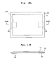
- bending detection electrodes 21E and 22E may be electrodes which are made of an electroconductive material arranged on the surface of the substrate 20, and which have an electrical resistor 48 of which an electric resistance changes according to the bending deformation of the substrate 20 (so called distortion gauge).
- the substrate 20 has an insulating property.
- the substrate may be formed of a resin material having the insulating property.
- the electrical resistors 48 having meandering sections (portions) 24E at two locations connected in parallel are arranged on the rear surface (lower surface) of the insulating substrate 20.
- the two meandering sections 24E are meandered in different directions, and in the meandering section 24E positioned at an upper-middle side in Fig. 15A , the electrical resistor 48 is meandered parallel to the short-side direction of the substrate 20, and in the meandering section 24E positioned at a lower side, the electrical resistor 48 is meandered parallel to the longitudinal direction of the substrate 20.
- These two meandering sections 24 form the two bending detections sections 21E and 22E (the first bending detection section 21E and the second bending detection section 22E).
- the insulating layer 26 is provided on the lower surface of the substrate 20, to cover the electrical resistor 48 completely.
- a bending detection section 21F may have two acceleration sensors 50 arranged at two locations (concretely, a left end portion and a right end portion) on the surface (lower surface) of the substrate 20. In this manner, it is possible to detect independently a movement (change of position) at two locations of the substrate 20 by the two acceleration sensors 50 provided at two different positions of the substrate 20. Therefore, it is possible to detect the bending deformation of the substrate 20, based on the position change at these two locations.
- the process of enlargement and reduction of the image, and the process of changing the image are allocated as the image changing process to be carried out by the display control section 32 for various modes of bending deformation of the substrate 20 which have been detected by the bending detection section.
- the display control section 32 which controls the display 13 is capable of controlling the display 13 to display one image as shown in Fig. 17A .
- the display control section 32 is also capable of controlling the display 13 to display a list of reduced images (thumbnail images) of a plurality of images (such as four). Therefore, when the bending deformation of the substrate 20 has been detected by the bending detections section, the display control section 32 may change the number of images to be displayed as a list on the display 13.
- the allocation of the image changing process in the seventh modified embodiment will be described below by citing an example of a case in which the input unit in the abovementioned first embodiment (refer to Fig. 9 ) in which five bending detections sections 41 to 45 are provided to the substrate 20 is adopted.
- the bending deformation at each five locations namely, the central portion, the right end portion, the left end portion, the upper end portion, and the lower end portion of the substrate 20 is detectable independently by each of the five bending detection sections 41 to 45 respectively.
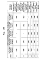
- the contents of the image changing process allocated to the bending deformation of the substrate 20 detected by the five bending detection sections 41 to 45 are shown in Figs. 18A and 18B .
- the display control section 32 increases the number of images displayed as a list on the display 13. Moreover, when the central portion of the substrate 20 is bent by the user to form a projection upward (frontward side) (item B in Figs. 18A and 18B ), the display control section 32 reduces (decreases) the number of image displayed as a list on the display 13. For example, when the substrate 20 is bent to form a projection downward, the state of the display 13 is changed from the standard display state in which one image is displayed entirely as shown in Fig.
- the display control section 32 when the plurality of images (thumbnail images) are displayed as a list on the display 13 and when the right end portion of the substrate 20 is bent to form a projection downward (item C in Figs. 18A and 18B ), the display control section 32, among the plurality of images displayed as a list on the display 13, selects newly an image positioned at right (side) of the image which has been selected currently. In other words, the display control section 32 changes the image selected to the image on the right side. "The image has been selected” indicates a state that the selected image is distinguished from the other images displayed as a list on the display 13 by surrounding the selected image by a thick frame, or making the selected image brighter, or making the selected image blink.
- the recording control section 30 makes the recording head record the image selected on the printing paper P.
- Fig. 19 is a perspective view of a printer of the second embodiment
- Fig. 20 is a block diagram showing schematically an electrical structure of the printer.
- an input unit 54 including a substrate 60 having flexibility, and bending detection sections 61 and 62 (a first bending detection section 61 and a second bending detection section 62) which detect the bending deformation of the substrate 60, is connected to a control unit 55 which is accommodated in the printer-body 6 via the cable 15.
- the second embodiment differs from the first embodiment at a point that a display 53 which displays an image is not provided to the substrate 60 of the input unit 54, but is provided on the inclined surface 6a formed at the upper portion of the printer-body 6, together with the plurality of operation buttons 12.
- the input unit 54 detects the bending deformation occurring in the substrate 60 by the two bending detection sections 61 and 62 (the first bending detection section 61 and the second bending detection section 62).
- the display control section 32 of the control unit 55 which controls the display 53 to change an image to be displayed on the display 53 based on the bending deformation of the substrate 60 which has been detected by the bending detections sections 61 and 62 (the first bending detection section 61 and the second bending detections section 62).
- the structure of the input unit 54 becomes simple. Moreover, unlike in a case in which the display 53 is provided integrally with the substrate 60 as in the structure in the first embodiment, since the display 53 is not particularly required to be flexible, a case of an image becoming difficult to see due to the bending of the display 53 does not arise.
- a printer 51 has a structure which makes the user identify a regular usage posture (attitude) or a structure which makes the user identify the current posture of the substrate 60.
- a posture identifying section which makes the user identify a regular usage posture (attitude) may be provided to the substrate 60.
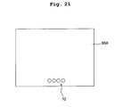
- an identifying section 70 including characters or a mark etc. on a part thereof may be provided to a substrate 60A.
- the user can make out at a glance whether the substrate 60A is at the regular posture by checking if the identifying section 70 including the characters or marks is inclined or in opposite direction.
- an arrow mark or a message indicating as to which direction of the substrate 60 is an upper portion in the regular usage posture may be disclosed on the substrate 60.
- a pair of handles 71 may be provided in both a left side and a right side of a substrate 60B at the regular usage attitude.
- the user is capable of identifying at once the regular usage posture (attitude) of the substrate 60B.
- a display 53C arranged on the inclined surface 6a of the printer-body 6 may have a vertically asymmetrical shape such as a trapezoidal shape as shown in Fig. 23A
- a substrate 60C may have a shape almost similar to the shape of the display 53C as shown in Fig. 23B .
- an external shape of the substrate 60 functions as a posture identifying section which makes the user identify the regular usage posture.
- the posture identifying section for identifying the usage posture of the substrate 60 is provided, the user, at the time of operating the substrate 60, is capable of identifying immediately as to by bending the substrate 60 at which posture, it is possible to carry out correctly the image change of the display 53.
- the printer 51 may include a structure (posture detection section) which detects a posture of the substrate 60.
- the printer 51 may include a posture detection sensor 75 made of a sensor such as a magnetic sensor which detects the posture of the substrate 60 operated at a location away from the printer-body 6.
- the control unit 55 of the printer 51 is capable of making a judgment of whether or not the substrate 60 is at the regular usage posture, from a detection result of the posture detection sensor 75. Therefore, when the substrate 60 is not at the regular usage posture, it is possible to inform the user by displaying an error message on the display 53.
- the posture of the substrate 60 can be detected from a result of the trial.
- a message requesting the user to bend the substrate 60 once on a trial basis is displayed on the display 53 before actually operating the input unit 54 (for example, immediately after the input unit 54 is removed by the user from a holder (not shown in the diagram) which sets the input unit 54 when not in use).
- the control unit 55 detects the posture of the substrate 60 based on the bending deformation of the substrate 60 detected by the bending detections sections 61 and 62 (the first bending detection section 61 and the second bending detection section 62). For example, when the bending detection sections 61 and 62 are provided at a right end portion of the substrate 60 which is at the regular usage posture, an instruction is given to the user to bend the right end portion of the substrate 60 inwardly (toward the user) on a trial basis, as it is in the current posture.
- the control unit 55 makes a judgment that the current posture is a regular usage posture.
- the control unit 55 makes a judgment that the current posture is a posture in which the left and right sides of the regular usage posture are reversed.
- the control unit 55 corresponds a posture detection section which detects the posture of the substrate 60 based on the result of detection by the bending detection sections 61 and 62.
- the input unit integrated with the display in the first embodiment is to be used by connecting to the printer including a recording head.
- an apparatus in which a display and an input unit are integrated can be used independently as an image display apparatus.
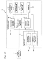
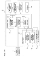
- Fig. 25 is a block diagram showing schematically an electrical structure of an image display apparatus 80 according to a third embodiment.
- the image display apparatus 80 includes an input unit 84 which includes a substrate and two bending detections sections 91 and 92 (a first bending detection section 91 and a second bending detection section 92) which detect the bending deformation of the substrate, a display 83 having flexibility which is deformable by being bent integrally with the substrate, and a control unit 85 which controls the display 83 based on a result of detection by the bending detection sections 91 and 92.
- the input unit 84 detects the bending deformation occurred in the substrate by the bending detection sections 91 and 92 .
- a display control section 82 of the control unit 85 which controls the display 83 changes an image to be displayed on the display 83 based on the bending deformation of the substrate detected by the bending detection sections 91 and 92.
- the image display apparatus 80 of the third embodiment has the control unit 85 formed by the CPU, the ROM, and the RAM etc., which is accommodated in the apparatus. Therefore, it is possible to store image data input from a data recording medium, in an image-data storage section 81 in the control unit 85. Moreover, when the user has bent the substrate, it is possible to display an image on the display 83 upon extracting image data from the image-data storage section 81 according to the mode of the bending deformation occurred in the substrate. In other words, it is possible to display an image on the display 83 without connecting to an equipment such as a printer. As a matter of course, it is also possible to use by connecting to a printer etc. as in the first embodiment.
- the shape of the substrate of the input unit may be arbitrary.
- the arrangement of the bending detection section to be arranged on the substrate is not restricted to the arrangement in the abovementioned embodiments and the modified embodiments, and the bending detection section may be arranged at an arbitrary position on the substrate, provided that it is possible to detect the bending at a target (intended) site.
Landscapes
- Engineering & Computer Science (AREA)
- Theoretical Computer Science (AREA)
- General Engineering & Computer Science (AREA)
- Physics & Mathematics (AREA)
- General Physics & Mathematics (AREA)
- Human Computer Interaction (AREA)
- Microelectronics & Electronic Packaging (AREA)
- Devices For Indicating Variable Information By Combining Individual Elements (AREA)
- Control Of Indicators Other Than Cathode Ray Tubes (AREA)
- Controls And Circuits For Display Device (AREA)
- Electroluminescent Light Sources (AREA)
- User Interface Of Digital Computer (AREA)
- Liquid Crystal (AREA)
Applications Claiming Priority (1)
| Application Number | Priority Date | Filing Date | Title |
|---|---|---|---|
| JP2007257250A JP2009086403A (ja) | 2007-10-01 | 2007-10-01 | 画像表示装置 |
Publications (2)
| Publication Number | Publication Date |
|---|---|
| EP2045701A2 true EP2045701A2 (de) | 2009-04-08 |
| EP2045701A3 EP2045701A3 (de) | 2013-01-23 |
Family
ID=40229826
Family Applications (1)
| Application Number | Title | Priority Date | Filing Date |
|---|---|---|---|
| EP08017307A Ceased EP2045701A3 (de) | 2007-10-01 | 2008-10-01 | Bildanzeigevorrichtung |
Country Status (4)
| Country | Link |
|---|---|
| US (1) | US8279170B2 (de) |
| EP (1) | EP2045701A3 (de) |
| JP (1) | JP2009086403A (de) |
| CN (3) | CN102156567A (de) |
Families Citing this family (41)
| Publication number | Priority date | Publication date | Assignee | Title |
|---|---|---|---|---|
| JP4946763B2 (ja) * | 2007-10-01 | 2012-06-06 | ブラザー工業株式会社 | 屈曲検出装置 |
| WO2010041227A1 (en) | 2008-10-12 | 2010-04-15 | Barit, Efrat | Flexible devices and related methods of use |
| JP4983831B2 (ja) | 2009-03-25 | 2012-07-25 | ブラザー工業株式会社 | 記録装置 |
| EP2315186B1 (de) | 2009-10-26 | 2016-09-21 | Lg Electronics Inc. | Mobiles Terminal mit flexiblem Gehäuse zur Eingabe eines Signals beim Biegen des Gehäuses |
| JP5440136B2 (ja) | 2009-12-04 | 2014-03-12 | ソニー株式会社 | 表示装置及び表示装置の制御方法 |
| JP5707694B2 (ja) * | 2009-12-04 | 2015-04-30 | ソニー株式会社 | 表示装置及び表示装置の制御方法 |
| US9632575B2 (en) | 2010-05-21 | 2017-04-25 | Nokia Technologies Oy | Method, an apparatus and a computer program for controlling an output from a display of an apparatus |
| CN102280047A (zh) * | 2010-06-11 | 2011-12-14 | 纬创资通股份有限公司 | 驱动装置、驱动方法及可携式电子显示装置 |
| KR20120059823A (ko) * | 2010-12-01 | 2012-06-11 | 삼성전자주식회사 | 객체 제어 장치 및 방법 |
| JP5373836B2 (ja) * | 2011-03-01 | 2013-12-18 | シャープ株式会社 | 操作指示装置及びそれを備えた画像形成装置 |
| JP5327256B2 (ja) | 2011-03-30 | 2013-10-30 | ブラザー工業株式会社 | 入力装置及び画像表示装置 |
| EP2696163B1 (de) * | 2011-04-08 | 2018-05-23 | Murata Manufacturing Co., Ltd. | Verschiebungssensor, verschiebungsdetektionsvorrichtung und betriebsvorrichtung |
| KR20130073621A (ko) * | 2011-12-23 | 2013-07-03 | 삼성전자주식회사 | 휴대용 단말기의 플렉시블 디스플레이 제어 방법 및 장치 |
| US9823707B2 (en) | 2012-01-25 | 2017-11-21 | Nokia Technologies Oy | Contortion of an electronic apparatus |
| US8610663B2 (en) * | 2012-02-06 | 2013-12-17 | Lg Electronics Inc. | Portable device and method for controlling the same |
| JP5733432B2 (ja) * | 2012-02-15 | 2015-06-10 | 株式会社村田製作所 | タッチ式入力端末 |
| US9804734B2 (en) * | 2012-02-24 | 2017-10-31 | Nokia Technologies Oy | Method, apparatus and computer program for displaying content |
| US9767605B2 (en) | 2012-02-24 | 2017-09-19 | Nokia Technologies Oy | Method and apparatus for presenting multi-dimensional representations of an image dependent upon the shape of a display |
| JP2013225052A (ja) * | 2012-04-23 | 2013-10-31 | Sony Corp | 表示装置 |
| US9823696B2 (en) | 2012-04-27 | 2017-11-21 | Nokia Technologies Oy | Limiting movement |
| DE102013207849B9 (de) | 2012-05-04 | 2017-01-12 | Beijing Lenovo Software Ltd. | Verfahren zum Bestimmen eines Biegezustands einer elektronischen Vorrichtung, elektronische Vorrichtung und flexibler Bildschirm |
| CN103383951B (zh) * | 2012-05-04 | 2016-10-05 | 联想(北京)有限公司 | 柔性屏、确定柔性屏弯折状态的方法及电子设备 |
| KR102052370B1 (ko) | 2012-06-14 | 2020-01-08 | 엘지전자 주식회사 | 플렉서블 포터블 디바이스 |
| KR101420330B1 (ko) * | 2012-06-22 | 2014-07-16 | 삼성디스플레이 주식회사 | 플렉시블 표시 장치 |
| KR101915064B1 (ko) * | 2012-08-23 | 2018-11-05 | 삼성전자주식회사 | 플렉서블 장치 및 그 동작 방법 |
| KR102088382B1 (ko) | 2012-09-07 | 2020-03-12 | 삼성전자주식회사 | 애플리케이션 실행 방법, 콘텐트 공유 제어 방법 및 디스플레이 장치 |
| JP5573912B2 (ja) * | 2012-10-04 | 2014-08-20 | ブラザー工業株式会社 | 画像表示装置 |
| CN103268176B (zh) * | 2012-12-11 | 2016-03-02 | 上海天马微电子有限公司 | 一种互感式电容触摸屏 |
| CN103902073B (zh) * | 2012-12-25 | 2019-01-04 | 深圳富泰宏精密工业有限公司 | 可弯曲式面板的操作控制方法及系统 |
| KR102145568B1 (ko) * | 2013-05-27 | 2020-08-31 | 삼성디스플레이 주식회사 | 동작 명령 안내 기능을 가지는 가요성 표시 장치 및 그 방법 |
| KR20150006191A (ko) * | 2013-07-08 | 2015-01-16 | 삼성전자주식회사 | 파노라마 이미지 운용 방법 및 그 전자 장치 |
| CN103594025A (zh) * | 2013-09-30 | 2014-02-19 | 友达光电股份有限公司 | 可挠式显示器 |
| US9858855B2 (en) | 2014-06-05 | 2018-01-02 | International Business Machines Corporation | Wearable display device |
| CN104318861B (zh) * | 2014-09-24 | 2017-05-10 | 京东方科技集团股份有限公司 | 一种柔性屏及其弯曲识别方法、柔性显示装置 |
| US9672587B2 (en) | 2014-12-12 | 2017-06-06 | International Business Machines Corporation | Rigid curved wearable display device |
| US10146257B2 (en) * | 2015-10-02 | 2018-12-04 | Microsoft Technology Licensing, Llc | Foldable device having sensor |
| CN112703547A (zh) * | 2018-10-30 | 2021-04-23 | 深圳市柔宇科技股份有限公司 | 触控显示面板与弯折检测方法 |
| CN110109513A (zh) * | 2019-04-22 | 2019-08-09 | 武汉华星光电半导体显示技术有限公司 | 可折叠显示屏 |
| CN110376820A (zh) * | 2019-07-22 | 2019-10-25 | 京东方科技集团股份有限公司 | 一种电子纸、其驱动方法及显示装置 |
| CN112885729B (zh) * | 2019-11-29 | 2022-12-13 | 成都辰显光电有限公司 | Led测试头、led测试装置及led测试装置的制备方法 |
| JP7396001B2 (ja) * | 2019-12-03 | 2023-12-12 | 京セラドキュメントソリューションズ株式会社 | 表示装置及び画像形成装置 |
Citations (2)
| Publication number | Priority date | Publication date | Assignee | Title |
|---|---|---|---|---|
| JP2006035662A (ja) | 2004-07-28 | 2006-02-09 | Brother Ind Ltd | 記録装置 |
| JP2007257250A (ja) | 2006-03-23 | 2007-10-04 | Kochi Univ Of Technology | 文字認識方法及びその装置及びそのプログラムを格納した記憶媒体 |
Family Cites Families (13)
| Publication number | Priority date | Publication date | Assignee | Title |
|---|---|---|---|---|
| US6943773B2 (en) * | 2001-05-11 | 2005-09-13 | Palmone, Inc. | Page flicking mechanism for electronic display devices that paginate content |
| KR100769783B1 (ko) | 2002-03-29 | 2007-10-24 | 가부시끼가이샤 도시바 | 표시 입력 장치 및 표시 입력 시스템 |
| JP4434609B2 (ja) * | 2002-03-29 | 2010-03-17 | 株式会社東芝 | 表示入力システム |
| US7456823B2 (en) * | 2002-06-14 | 2008-11-25 | Sony Corporation | User interface apparatus and portable information apparatus |
| JP4222160B2 (ja) | 2002-10-30 | 2009-02-12 | ソニー株式会社 | 入力装置およびその製造方法 |
| US7701445B2 (en) | 2002-10-30 | 2010-04-20 | Sony Corporation | Input device and process for manufacturing the same, portable electronic apparatus comprising input device |
| JP3816457B2 (ja) | 2003-03-18 | 2006-08-30 | 株式会社東芝 | 表示装置 |
| JP2005174006A (ja) * | 2003-12-11 | 2005-06-30 | Canon Inc | 表示装置 |
| US7712891B2 (en) | 2003-12-26 | 2010-05-11 | Brother Kogyo Kabushiki Kaisha | Image-forming device |
| US20070205997A1 (en) * | 2004-03-29 | 2007-09-06 | Koninklijke Philips Electronics N.V. | Controlling A Visual Display By Bending |
| JP4869568B2 (ja) | 2004-06-14 | 2012-02-08 | ソニー株式会社 | 入力装置および電子機器 |
| US20060238494A1 (en) * | 2005-04-22 | 2006-10-26 | International Business Machines Corporation | Flexible displays as an input device |
| US20080253643A1 (en) * | 2007-04-13 | 2008-10-16 | Chun-Nan Wu | Component inspection imaging apparatus structure |
-
2007
- 2007-10-01 JP JP2007257250A patent/JP2009086403A/ja active Pending
-
2008
- 2008-09-25 CN CN2010106217220A patent/CN102156567A/zh active Pending
- 2008-09-25 CN CN2008101662761A patent/CN101403839B/zh active Active
- 2008-09-25 CN CN2010106216745A patent/CN102156566A/zh active Pending
- 2008-09-30 US US12/286,318 patent/US8279170B2/en active Active
- 2008-10-01 EP EP08017307A patent/EP2045701A3/de not_active Ceased
Patent Citations (2)
| Publication number | Priority date | Publication date | Assignee | Title |
|---|---|---|---|---|
| JP2006035662A (ja) | 2004-07-28 | 2006-02-09 | Brother Ind Ltd | 記録装置 |
| JP2007257250A (ja) | 2006-03-23 | 2007-10-04 | Kochi Univ Of Technology | 文字認識方法及びその装置及びそのプログラムを格納した記憶媒体 |
Non-Patent Citations (1)
| Title |
|---|
| DAVID D. BUSCH: "HP Photosmart 475 Compact Photo Printer - printer - color - ink-jet review", 22 September 2005 (2005-09-22), Retrieved from the Internet <URL:http://www.cnet.com/products/hp-photosmart-475-compact-photo-printer-printer-color-ink-jet-series/> [retrieved on 20150914] * |
Also Published As
| Publication number | Publication date |
|---|---|
| CN102156567A (zh) | 2011-08-17 |
| CN101403839B (zh) | 2011-03-09 |
| CN102156566A (zh) | 2011-08-17 |
| US8279170B2 (en) | 2012-10-02 |
| JP2009086403A (ja) | 2009-04-23 |
| CN101403839A (zh) | 2009-04-08 |
| US20090085866A1 (en) | 2009-04-02 |
| EP2045701A3 (de) | 2013-01-23 |
Similar Documents
| Publication | Publication Date | Title |
|---|---|---|
| EP2045701A2 (de) | Bildanzeigevorrichtung | |
| US7946183B2 (en) | Bending-detection apparatus | |
| US8866737B2 (en) | Input device and image display apparatus | |
| JP4983831B2 (ja) | 記録装置 | |
| US20080307355A1 (en) | Operating apparatus, image forming apparatus, computer readable recording medium and method for controlling display panel | |
| JP5032919B2 (ja) | 画像処理装置、印刷プレビュー方法及びプログラム | |
| JP4905287B2 (ja) | プリンタ | |
| JP5176889B2 (ja) | 画像表示装置 | |
| JP2002137499A (ja) | 画像形成装置、画像形成方法、印刷装置、印刷方法、及び記憶媒体 | |
| US7839057B2 (en) | Movement detector | |
| JP5573912B2 (ja) | 画像表示装置 | |
| JP5884858B2 (ja) | 画像表示装置 | |
| JP4785457B2 (ja) | 表示制御装置及び表示制御方法 | |
| CN115593103B (zh) | 印刷装置 | |
| CN115593102B (zh) | 印刷装置 | |
| JP4569375B2 (ja) | プリント注文受付装置 | |
| US8441681B2 (en) | Printing apparatus for printing composite image, print data generating apparatus for generating print data of composite image, and print data generating program for generating print data of composite image | |
| JP2007118221A (ja) | 印刷装置、印刷処理プログラム、及び印刷処理システム | |
| JP2009196755A (ja) | 用紙後処理システム | |
| JP2009043011A (ja) | 電子書籍用ページめくり操作機器及び電子書籍端末 | |
| JP2004297585A (ja) | 撮像装置 |
Legal Events
| Date | Code | Title | Description |
|---|---|---|---|
| PUAI | Public reference made under article 153(3) epc to a published international application that has entered the european phase |
Free format text: ORIGINAL CODE: 0009012 |
|
| AK | Designated contracting states |
Kind code of ref document: A2 Designated state(s): AT BE BG CH CY CZ DE DK EE ES FI FR GB GR HR HU IE IS IT LI LT LU LV MC MT NL NO PL PT RO SE SI SK TR |
|
| AX | Request for extension of the european patent |
Extension state: AL BA MK RS |
|
| PUAL | Search report despatched |
Free format text: ORIGINAL CODE: 0009013 |
|
| AK | Designated contracting states |
Kind code of ref document: A3 Designated state(s): AT BE BG CH CY CZ DE DK EE ES FI FR GB GR HR HU IE IS IT LI LT LU LV MC MT NL NO PL PT RO SE SI SK TR |
|
| AX | Request for extension of the european patent |
Extension state: AL BA MK RS |
|
| RIC1 | Information provided on ipc code assigned before grant |
Ipc: G06F 3/041 20060101ALI20121219BHEP Ipc: G06F 3/00 20060101ALI20121219BHEP Ipc: G06F 3/048 20130101AFI20121219BHEP Ipc: G03G 15/00 20060101ALI20121219BHEP |
|
| 17P | Request for examination filed |
Effective date: 20130717 |
|
| RBV | Designated contracting states (corrected) |
Designated state(s): AT BE BG CH CY CZ DE DK EE ES FI FR GB GR HR HU IE IS IT LI LT LU LV MC MT NL NO PL PT RO SE SI SK TR |
|
| AKX | Designation fees paid |
Designated state(s): AT BE BG CH CY CZ DE DK EE ES FI FR GB GR HR HU IE IS IT LI LT LU LV MC MT NL NO PL PT RO SE SI SK TR |
|
| 17Q | First examination report despatched |
Effective date: 20131218 |
|
| STAA | Information on the status of an ep patent application or granted ep patent |
Free format text: STATUS: THE APPLICATION HAS BEEN REFUSED |
|
| 18R | Application refused |
Effective date: 20151007 |