EP2045826A2 - Elektrische Schalteranordnung - Google Patents
Elektrische Schalteranordnung Download PDFInfo
- Publication number
- EP2045826A2 EP2045826A2 EP08158408A EP08158408A EP2045826A2 EP 2045826 A2 EP2045826 A2 EP 2045826A2 EP 08158408 A EP08158408 A EP 08158408A EP 08158408 A EP08158408 A EP 08158408A EP 2045826 A2 EP2045826 A2 EP 2045826A2
- Authority
- EP
- European Patent Office
- Prior art keywords
- knob
- base plate
- aperture
- shaft
- electrical switch
- Prior art date
- Legal status (The legal status is an assumption and is not a legal conclusion. Google has not performed a legal analysis and makes no representation as to the accuracy of the status listed.)
- Granted
Links
Images


Classifications
-
- H—ELECTRICITY
- H01—ELECTRIC ELEMENTS
- H01H—ELECTRIC SWITCHES; RELAYS; SELECTORS; EMERGENCY PROTECTIVE DEVICES
- H01H25/00—Switches with compound movement of handle or other operating part
- H01H25/06—Operating part movable both angularly and rectilinearly, the rectilinear movement being along the axis of angular movement
-
- G—PHYSICS
- G05—CONTROLLING; REGULATING
- G05G—CONTROL DEVICES OR SYSTEMS INSOFAR AS CHARACTERISED BY MECHANICAL FEATURES ONLY
- G05G9/00—Manually-actuated control mechanisms provided with one single controlling member co-operating with two or more controlled members, e.g. selectively, simultaneously
- G05G9/02—Manually-actuated control mechanisms provided with one single controlling member co-operating with two or more controlled members, e.g. selectively, simultaneously the controlling member being movable in different independent ways, movement in each individual way actuating one controlled member only
- G05G9/04—Manually-actuated control mechanisms provided with one single controlling member co-operating with two or more controlled members, e.g. selectively, simultaneously the controlling member being movable in different independent ways, movement in each individual way actuating one controlled member only in which movement in two or more ways can occur simultaneously
- G05G9/047—Manually-actuated control mechanisms provided with one single controlling member co-operating with two or more controlled members, e.g. selectively, simultaneously the controlling member being movable in different independent ways, movement in each individual way actuating one controlled member only in which movement in two or more ways can occur simultaneously the controlling member being movable by hand about orthogonal axes, e.g. joysticks
-
- H—ELECTRICITY
- H01—ELECTRIC ELEMENTS
- H01H—ELECTRIC SWITCHES; RELAYS; SELECTORS; EMERGENCY PROTECTIVE DEVICES
- H01H25/00—Switches with compound movement of handle or other operating part
- H01H25/002—Switches with compound movement of handle or other operating part having an operating member rectilinearly slidable in different directions
-
- G—PHYSICS
- G05—CONTROLLING; REGULATING
- G05G—CONTROL DEVICES OR SYSTEMS INSOFAR AS CHARACTERISED BY MECHANICAL FEATURES ONLY
- G05G9/00—Manually-actuated control mechanisms provided with one single controlling member co-operating with two or more controlled members, e.g. selectively, simultaneously
- G05G9/02—Manually-actuated control mechanisms provided with one single controlling member co-operating with two or more controlled members, e.g. selectively, simultaneously the controlling member being movable in different independent ways, movement in each individual way actuating one controlled member only
- G05G9/04—Manually-actuated control mechanisms provided with one single controlling member co-operating with two or more controlled members, e.g. selectively, simultaneously the controlling member being movable in different independent ways, movement in each individual way actuating one controlled member only in which movement in two or more ways can occur simultaneously
- G05G9/047—Manually-actuated control mechanisms provided with one single controlling member co-operating with two or more controlled members, e.g. selectively, simultaneously the controlling member being movable in different independent ways, movement in each individual way actuating one controlled member only in which movement in two or more ways can occur simultaneously the controlling member being movable by hand about orthogonal axes, e.g. joysticks
- G05G2009/04703—Mounting of controlling member
- G05G2009/04714—Mounting of controlling member with orthogonal axes
- G05G2009/04718—Mounting of controlling member with orthogonal axes with cardan or gimbal type joint
-
- G—PHYSICS
- G05—CONTROLLING; REGULATING
- G05G—CONTROL DEVICES OR SYSTEMS INSOFAR AS CHARACTERISED BY MECHANICAL FEATURES ONLY
- G05G9/00—Manually-actuated control mechanisms provided with one single controlling member co-operating with two or more controlled members, e.g. selectively, simultaneously
- G05G9/02—Manually-actuated control mechanisms provided with one single controlling member co-operating with two or more controlled members, e.g. selectively, simultaneously the controlling member being movable in different independent ways, movement in each individual way actuating one controlled member only
- G05G9/04—Manually-actuated control mechanisms provided with one single controlling member co-operating with two or more controlled members, e.g. selectively, simultaneously the controlling member being movable in different independent ways, movement in each individual way actuating one controlled member only in which movement in two or more ways can occur simultaneously
- G05G9/047—Manually-actuated control mechanisms provided with one single controlling member co-operating with two or more controlled members, e.g. selectively, simultaneously the controlling member being movable in different independent ways, movement in each individual way actuating one controlled member only in which movement in two or more ways can occur simultaneously the controlling member being movable by hand about orthogonal axes, e.g. joysticks
- G05G2009/04777—Manually-actuated control mechanisms provided with one single controlling member co-operating with two or more controlled members, e.g. selectively, simultaneously the controlling member being movable in different independent ways, movement in each individual way actuating one controlled member only in which movement in two or more ways can occur simultaneously the controlling member being movable by hand about orthogonal axes, e.g. joysticks with additional push or pull action on the handle
-
- G—PHYSICS
- G05—CONTROLLING; REGULATING
- G05G—CONTROL DEVICES OR SYSTEMS INSOFAR AS CHARACTERISED BY MECHANICAL FEATURES ONLY
- G05G9/00—Manually-actuated control mechanisms provided with one single controlling member co-operating with two or more controlled members, e.g. selectively, simultaneously
- G05G9/02—Manually-actuated control mechanisms provided with one single controlling member co-operating with two or more controlled members, e.g. selectively, simultaneously the controlling member being movable in different independent ways, movement in each individual way actuating one controlled member only
- G05G9/04—Manually-actuated control mechanisms provided with one single controlling member co-operating with two or more controlled members, e.g. selectively, simultaneously the controlling member being movable in different independent ways, movement in each individual way actuating one controlled member only in which movement in two or more ways can occur simultaneously
- G05G9/047—Manually-actuated control mechanisms provided with one single controlling member co-operating with two or more controlled members, e.g. selectively, simultaneously the controlling member being movable in different independent ways, movement in each individual way actuating one controlled member only in which movement in two or more ways can occur simultaneously the controlling member being movable by hand about orthogonal axes, e.g. joysticks
- G05G2009/04781—Manually-actuated control mechanisms provided with one single controlling member co-operating with two or more controlled members, e.g. selectively, simultaneously the controlling member being movable in different independent ways, movement in each individual way actuating one controlled member only in which movement in two or more ways can occur simultaneously the controlling member being movable by hand about orthogonal axes, e.g. joysticks with additional rotation of the controlling member
-
- H—ELECTRICITY
- H01—ELECTRIC ELEMENTS
- H01H—ELECTRIC SWITCHES; RELAYS; SELECTORS; EMERGENCY PROTECTIVE DEVICES
- H01H25/00—Switches with compound movement of handle or other operating part
- H01H25/002—Switches with compound movement of handle or other operating part having an operating member rectilinearly slidable in different directions
- H01H2025/004—Switches with compound movement of handle or other operating part having an operating member rectilinearly slidable in different directions the operating member being depressable perpendicular to the other directions
-
- H—ELECTRICITY
- H01—ELECTRIC ELEMENTS
- H01H—ELECTRIC SWITCHES; RELAYS; SELECTORS; EMERGENCY PROTECTIVE DEVICES
- H01H2237/00—Mechanism between key and laykey
- H01H2237/006—Guided plunger or ball
Definitions
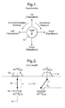
- the present invention relates to an electrical switch assembly in which the switch knob has the capability of movement in different directions and in which the switch assembly has multiple switch actions or functions.
- An electrical switch assembly in accordance with the present invention comprises a base plate; depressible switch buttons mounted on the base plate and including electrical switch contacts; a cover plate spaced from the base plate and extending in a plane substantially parallel to the plane of the base plate; an aperture in the cover plate having a centre aligned with an axis, the axis being substantially perpendicular to the plane of the base plate; a knob located on the opposite side of the cover plate to the base plate, the knob having a shaft extending through the aperture, the aperture having a predetermined size and shape to restrict the translational movement of the knob shaft in the aperture to predetermined directions away from the centre of the aperture; actuating means secured to the knob shaft on the opposition side of the cover plate to the knob, the actuating means having chamfered surfaces at predetermined positions; actuating rods extending in a direction substantially parallel to the axis between the switch buttons and the actuating means, at least one of the rods being selectively engageable with an associated one of the chamfered surfaces on translational movement
- the cardan shaft and joints allow the knob to move in a translational direction away from the aperture centre and axis whilst maintaining the knob in the same orientation relative to the cover plate.
- the cardan shaft and joints also allow rotation of the knob to cause rotation of the encoder; and allow depression of the knob to cause depression of the encoder and the actuator. Any one of these movements of the knob, either individually or simultaneously, causing actuation of one or more switch contacts on the base plate.
- an electrical switch assembly 10 in accordance with the present invention comprises a base plate 12 with depressible switch buttons 14 mounted thereon, each button including electrical switch contacts (not shown) for actuation or de-actuation of an associated electrical load (not shown).
- the base plate 12 is preferably a printed circuit board.
- a depressible actuator 16 which functions as or acts on an electrical switch, is also mounted on the base plate 12.
- the electrical switch of the actuator 16 is electrically connected to a number of electrical loads (not shown) by way of a control module (not shown) for actuation or de-actuation of the electrical loads.
- An encoder 18 is associated with, and engageable with, the actuator 16 on the opposite side of the actuator to the base plate 12.
- the encoder 18 is also connected to the control module (not shown).
- the encoder 18 is rotatable about an axis A relative to the actuator 16, the axis being substantially perpendicular to plane of the base plate 12.
- the rotational position of the encoder 18 relative to the base plate 12 generates a signal which is sent to the control module which determines which electrical load is actuated or de-actuated by subsequent depression of the actuator 16.
- the encoder 18 is preferably cup-shaped and has an outer wall 44 which is castellated.
- the outer wall 44 passes through an optical reader 46 ( Figure 10 ), which is mounted on the base plate 12, on rotation of the encoder 18 to generate the signal.
- the encoder may be substantially flat with the outer edge being castellated.
- the encoder may take other suitable forms, and/or may generate the signal by other means, such as by a magnetic arrangement rather than an optical arrangement.
- a cover plate 20 is spaced from the base plate 12 and extends in a plane substantially parallel to the plane of the base plate.
- An aperture 22 in the cover plate 20 has a centre aligned with the axis A.
- a knob 24 is located on the opposite side of the cover plate 20 to the base plate 12, the knob having a shaft 26 extending through the aperture 22.
- the aperture 22 has a predetermined size and shape to allow rotation of the knob shaft 26 at any position within the aperture but to restrict the translational movement of the knob shaft in the aperture to predetermined directions away from the centre of the aperture.
- the aperture 22 is preferably in the form of a cross, as shown in Figure 4 .
- the aperture 22 comprises four slots 22A-D extending away from the centre of the aperture, with opposed slots 22A-B, 22C-D being aligned and the aligned pairs of slots crossing at substantially ninety degrees to one another.
- the aligned pairs of slots may cross at an angle other than ninety degrees.
- the aperture may comprise only two slots, or three slots defining a substantially Y-shape, or any other suitable number of slots and configuration.
- the shape of the aperture 22 determines the possible or allowable paths for the translation movement of the knob 24 relative to the cover 20.
- Resilient means (not shown) may be provided to bias the knob 24 and knob shaft 26 to the centre of the aperture 22, for example one or more springs acting on the knob shaft 26.
- actuating means 28 are secured to the knob shaft 26 on the opposition side of the cover plate 20 to the knob 24.
- the resilient means biasing the knob 24 to the centre of the aperture 22 may be one or more springs (not shown) acting on the outer circumferential edge 29 of the actuating means 28.
- the actuating means 28 has chamfered surfaces 30 at predetermined positions adjacent its circumferential edge. The chamfered surfaces 30 extend at an angle to the plane of the cover plate 20 or base plate 12 from adjacent the outer circumferential edge 29 towards the rotation axis A.
- Actuating rods 32 ( Figure 5 ) extend between the switch buttons 14 and the actuating means 28. Each actuating rod 32 is selectively engageable with one of the chamfered surfaces 30.
- Each actuating rod 32 is slidably positioned within a substantially rigid tube 33.
- Each tube 33 is fixed relative to the base plate 12 and located above a switch button 14.
- Each tube 33 has a longitudinal axis which is substantially parallel to the rotation axis A, thereby restricting movement of the associated rod 32 to translational movement in a direction substantially parallel to the rotation axis A.
- Translational movement of the knob 24 away from the centre of the aperture 22, that is away from the rotation axis A causes the actuating means 28 to move in the same direction. Movement of the actuating means 28 causes a chamfered surface 30 to engage its associated actuating rod 32, causing sliding movement of the rod in its associated tube 33, thereby causing depression of (and actuation of) the switch button 14 associated with that rod.
- a cardan shaft 34 extends between the knob shaft 26 and the encoder 18.
- a first cardan joint 36 connects one end of the cardan shaft 34 to the knob shaft 26.
- a second cardan joint 38 connects the other end of the cardan shaft 34 to the encoder 18.
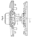
- the cardan shaft 34 is extendable in length (as shown in Figure 2 ).
- the cardan shaft 34 preferably comprises two axially extending parts 40, 42 which are linked together, and which are preferably substantially identical.
- the two parts 40, 42 are keyed together at adjacent ends (the opposed ends to the joints 36, 38) by means which allow lengthwise extension of the cardan shaft 34 and which ensure simultaneous rotation of the two parts.
- the keying means is preferably a tongue-and-groove arrangement.
- Resilient means may be associated with the keying means (for example, a spring positioned between the keyed adjacent ends of the parts 40, 42, and tending to extend or compress the length of the cardan shaft 34) to take up any play between the two parts.
- the resilient means may be the same as the resilient means provided to bias the knob 24 and knob shaft 26 to the centre of the aperture 22.
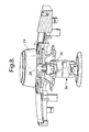
- the longitudinal axis Z of the cardan shaft 34 normally extends along the rotation axis A ( Figure 6 ).
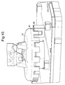
- the knob 24 is moved in a translational direction relative to the cover plate 20, the longitudinal axis Z of the cardan shaft 34 is orientated at an angle to the rotation axis A ( Figure 7 ), however rotation of the knob 24, and hence rotation of the cardan shaft 34 and the encoder 18 is still possible. Further, if the knob 24 is pushed (depressed) towards the cover plate 20, the encoder 18 is pushed towards the depressible actuator 16 to actuate or de-actuate an electrical load dependent on the rotational position of the encode 18 relative to the base plate 12, as described above. Where a spring is associated with the keying means, pushing of the knob 24 to depress the depressible actuator 16 is possible in any position of the knob 24 within the aperture 22, as well as when the knob 24 is positioned at the centre of the aperture.
- the present invention provides an electrical switch assembly in which several switch functions are possible using a single switch knob.
- the knob is capable of translation movement, rotational movement, and depression (returnable push movement) relative to a cover plate 20. Additionally, translational movement of the knob does not cause the knob to tilt relative to the cover plate.
- the present invention may be used in conjunction with the motion control assembly described and claimed in EP patent application no. (Applicant's reference DP-317147) filed the same day as the present application.
Landscapes
- Physics & Mathematics (AREA)
- General Physics & Mathematics (AREA)
- Engineering & Computer Science (AREA)
- Automation & Control Theory (AREA)
- Rotary Switch, Piano Key Switch, And Lever Switch (AREA)
Applications Claiming Priority (1)
| Application Number | Priority Date | Filing Date | Title |
|---|---|---|---|
| GB0719265A GB0719265D0 (en) | 2007-10-03 | 2007-10-03 | Electrical switch assembly |
Publications (3)
| Publication Number | Publication Date |
|---|---|
| EP2045826A2 true EP2045826A2 (de) | 2009-04-08 |
| EP2045826A3 EP2045826A3 (de) | 2011-10-12 |
| EP2045826B1 EP2045826B1 (de) | 2012-10-31 |
Family
ID=38739022
Family Applications (1)
| Application Number | Title | Priority Date | Filing Date |
|---|---|---|---|
| EP20080158408 Not-in-force EP2045826B1 (de) | 2007-10-03 | 2008-06-17 | Elektrische Schalteranordnung |
Country Status (2)
| Country | Link |
|---|---|
| EP (1) | EP2045826B1 (de) |
| GB (1) | GB0719265D0 (de) |
Cited By (7)
| Publication number | Priority date | Publication date | Assignee | Title |
|---|---|---|---|---|
| DE102013008772A1 (de) | 2013-05-23 | 2014-11-27 | Audi Ag | Bedienelement für ein Kraftfahrzeug |
| CN107450654A (zh) * | 2017-07-04 | 2017-12-08 | 罗江祺 | 一种烹调器的倾斜旋钮传动结构及应用该结构的烹调器 |
| US20190139723A1 (en) * | 2017-11-08 | 2019-05-09 | Kabushiki Kaisha Tokai Rika Denki Seisakusho | Switch operation mechanism |
| CN110896010A (zh) * | 2018-09-13 | 2020-03-20 | 上海擎感智能科技有限公司 | 一种多功能旋钮组件 |
| CN113871242A (zh) * | 2021-09-27 | 2021-12-31 | 浙江吉利控股集团有限公司 | 一种摇杆开关结构 |
| CN114401859A (zh) * | 2019-09-17 | 2022-04-26 | 采埃孚股份公司 | 尤其用于机动车辆的设备的操作设备 |
| DE102022115779A1 (de) * | 2022-06-24 | 2024-01-04 | Signata GmbH | Bedienanordnung mit einem Bedienknauf |
Family Cites Families (4)
| Publication number | Priority date | Publication date | Assignee | Title |
|---|---|---|---|---|
| US3918021A (en) * | 1974-06-17 | 1975-11-04 | Matsushita Electric Industrial Co Ltd | Device for simultaneously controlling a plurality of variable resistors |
| DE3838362C1 (de) * | 1988-11-11 | 1990-01-11 | Nixdorf Computer Ag, 4790 Paderborn, De | |
| JP2002373050A (ja) * | 2001-06-13 | 2002-12-26 | Aiwa Co Ltd | 操作装置 |
| EP1750194B1 (de) * | 2005-08-05 | 2010-05-05 | Niles Co., Ltd. | Multidirektionale Eingabevorrichtung |
-
2007
- 2007-10-03 GB GB0719265A patent/GB0719265D0/en not_active Ceased
-
2008
- 2008-06-17 EP EP20080158408 patent/EP2045826B1/de not_active Not-in-force
Cited By (13)
| Publication number | Priority date | Publication date | Assignee | Title |
|---|---|---|---|---|
| DE102013008772A1 (de) | 2013-05-23 | 2014-11-27 | Audi Ag | Bedienelement für ein Kraftfahrzeug |
| CN107450654A (zh) * | 2017-07-04 | 2017-12-08 | 罗江祺 | 一种烹调器的倾斜旋钮传动结构及应用该结构的烹调器 |
| CN107450654B (zh) * | 2017-07-04 | 2018-11-13 | 罗江祺 | 一种烹调器的倾斜旋钮传动结构及应用该结构的烹调器 |
| US10984971B2 (en) | 2017-11-08 | 2021-04-20 | Kabushiki Kaisha Tokai Rika Denki Seisakusho | Switch operation mechanism |
| US20190139723A1 (en) * | 2017-11-08 | 2019-05-09 | Kabushiki Kaisha Tokai Rika Denki Seisakusho | Switch operation mechanism |
| CN109755063A (zh) * | 2017-11-08 | 2019-05-14 | 株式会社东海理化电机制作所 | 开关操作机构 |
| EP3483695A1 (de) * | 2017-11-08 | 2019-05-15 | Kabushiki Kaisha Tokai Rika Denki Seisakusho | Schaltoperationsmechanismus |
| CN110896010A (zh) * | 2018-09-13 | 2020-03-20 | 上海擎感智能科技有限公司 | 一种多功能旋钮组件 |
| CN110896010B (zh) * | 2018-09-13 | 2023-11-28 | 上海擎感智能科技有限公司 | 一种多功能旋钮组件 |
| CN114401859A (zh) * | 2019-09-17 | 2022-04-26 | 采埃孚股份公司 | 尤其用于机动车辆的设备的操作设备 |
| CN113871242A (zh) * | 2021-09-27 | 2021-12-31 | 浙江吉利控股集团有限公司 | 一种摇杆开关结构 |
| CN113871242B (zh) * | 2021-09-27 | 2024-04-12 | 浙江吉利控股集团有限公司 | 一种摇杆开关结构 |
| DE102022115779A1 (de) * | 2022-06-24 | 2024-01-04 | Signata GmbH | Bedienanordnung mit einem Bedienknauf |
Also Published As
| Publication number | Publication date |
|---|---|
| EP2045826A3 (de) | 2011-10-12 |
| EP2045826B1 (de) | 2012-10-31 |
| GB0719265D0 (en) | 2007-11-14 |
Similar Documents
| Publication | Publication Date | Title |
|---|---|---|
| EP2045826B1 (de) | Elektrische Schalteranordnung | |
| US5424516A (en) | Low profile pushbutton switch | |
| US4414438A (en) | Video game controller | |
| US4469330A (en) | Controller unit for video game | |
| EP0016886B1 (de) | X-Y-Steuervorrichtung | |
| JP5652846B2 (ja) | シフトバイワイヤギアシフト装置 | |
| KR20150028817A (ko) | 특히 차량 부품용 다기능 작동 장치 | |
| CN101443870A (zh) | 操纵杆型开关装置 | |
| EP1524579A2 (de) | Schaltgerät in Form eines Joystick | |
| CN115775704A (zh) | 多路输入装置 | |
| JP3975199B2 (ja) | 多方向スイッチ装置、並びにスイッチモジュール | |
| CA1184475A (en) | Sliding disc transducer actuator | |
| EP1208575B1 (de) | Auf einer kardanischen aufhängung montierte multifunktionelle taste | |
| US9343249B2 (en) | Pressure and rotationally actuated control element for a motor vehicle | |
| US6642685B2 (en) | Force-feedback input device containing two tilt position detection means for operating member | |
| CN1233007C (zh) | 多方向输入装置 | |
| US6903291B2 (en) | Multi-way electric switch having operator control supported by two orthogonal parallel linkages coupled via intermediate part | |
| KR102193126B1 (ko) | 슬라이드 스위치 유니트 | |
| US6844510B2 (en) | Stalk switch | |
| JP4268537B2 (ja) | 多方向入力装置 | |
| WO2018079147A1 (ja) | 多方向入力装置 | |
| US20250291434A1 (en) | Mouse button structure and mouse device having the same | |
| WO2018016600A1 (ja) | 操作装置 | |
| EP2136289B1 (de) | Bewegungssteueranordnung | |
| KR102546960B1 (ko) | 4방향 시소 및 푸시 기능을 구비한 순간형 스위치 |
Legal Events
| Date | Code | Title | Description |
|---|---|---|---|
| PUAI | Public reference made under article 153(3) epc to a published international application that has entered the european phase |
Free format text: ORIGINAL CODE: 0009012 |
|
| AK | Designated contracting states |
Kind code of ref document: A2 Designated state(s): AT BE BG CH CY CZ DE DK EE ES FI FR GB GR HR HU IE IS IT LI LT LU LV MC MT NL NO PL PT RO SE SI SK TR |
|
| AX | Request for extension of the european patent |
Extension state: AL BA MK RS |
|
| PUAL | Search report despatched |
Free format text: ORIGINAL CODE: 0009013 |
|
| AK | Designated contracting states |
Kind code of ref document: A3 Designated state(s): AT BE BG CH CY CZ DE DK EE ES FI FR GB GR HR HU IE IS IT LI LT LU LV MC MT NL NO PL PT RO SE SI SK TR |
|
| AX | Request for extension of the european patent |
Extension state: AL BA MK RS |
|
| RIC1 | Information provided on ipc code assigned before grant |
Ipc: H01H 25/06 20060101ALI20110907BHEP Ipc: H01H 25/00 20060101AFI20110907BHEP |
|
| 17P | Request for examination filed |
Effective date: 20120412 |
|
| GRAP | Despatch of communication of intention to grant a patent |
Free format text: ORIGINAL CODE: EPIDOSNIGR1 |
|
| AKX | Designation fees paid |
Designated state(s): AT BE BG CH CY CZ DE DK EE ES FI FR GB GR HR HU IE IS IT LI LT LU LV MC MT NL NO PL PT RO SE SI SK TR |
|
| GRAS | Grant fee paid |
Free format text: ORIGINAL CODE: EPIDOSNIGR3 |
|
| GRAA | (expected) grant |
Free format text: ORIGINAL CODE: 0009210 |
|
| AK | Designated contracting states |
Kind code of ref document: B1 Designated state(s): AT BE BG CH CY CZ DE DK EE ES FI FR GB GR HR HU IE IS IT LI LT LU LV MC MT NL NO PL PT RO SE SI SK TR |
|
| REG | Reference to a national code |
Ref country code: GB Ref legal event code: FG4D Ref country code: CH Ref legal event code: EP |
|
| REG | Reference to a national code |
Ref country code: AT Ref legal event code: REF Ref document number: 582406 Country of ref document: AT Kind code of ref document: T Effective date: 20121115 |
|
| REG | Reference to a national code |
Ref country code: IE Ref legal event code: FG4D |
|
| REG | Reference to a national code |
Ref country code: DE Ref legal event code: R096 Ref document number: 602008019730 Country of ref document: DE Effective date: 20121227 |
|
| REG | Reference to a national code |
Ref country code: AT Ref legal event code: MK05 Ref document number: 582406 Country of ref document: AT Kind code of ref document: T Effective date: 20121031 |
|
| REG | Reference to a national code |
Ref country code: LT Ref legal event code: MG4D |
|
| REG | Reference to a national code |
Ref country code: NL Ref legal event code: VDEP Effective date: 20121031 |
|
| PG25 | Lapsed in a contracting state [announced via postgrant information from national office to epo] |
Ref country code: IS Free format text: LAPSE BECAUSE OF FAILURE TO SUBMIT A TRANSLATION OF THE DESCRIPTION OR TO PAY THE FEE WITHIN THE PRESCRIBED TIME-LIMIT Effective date: 20130228 Ref country code: SE Free format text: LAPSE BECAUSE OF FAILURE TO SUBMIT A TRANSLATION OF THE DESCRIPTION OR TO PAY THE FEE WITHIN THE PRESCRIBED TIME-LIMIT Effective date: 20121031 Ref country code: FI Free format text: LAPSE BECAUSE OF FAILURE TO SUBMIT A TRANSLATION OF THE DESCRIPTION OR TO PAY THE FEE WITHIN THE PRESCRIBED TIME-LIMIT Effective date: 20121031 Ref country code: ES Free format text: LAPSE BECAUSE OF FAILURE TO SUBMIT A TRANSLATION OF THE DESCRIPTION OR TO PAY THE FEE WITHIN THE PRESCRIBED TIME-LIMIT Effective date: 20130211 Ref country code: NL Free format text: LAPSE BECAUSE OF FAILURE TO SUBMIT A TRANSLATION OF THE DESCRIPTION OR TO PAY THE FEE WITHIN THE PRESCRIBED TIME-LIMIT Effective date: 20121031 Ref country code: NO Free format text: LAPSE BECAUSE OF FAILURE TO SUBMIT A TRANSLATION OF THE DESCRIPTION OR TO PAY THE FEE WITHIN THE PRESCRIBED TIME-LIMIT Effective date: 20130131 Ref country code: HR Free format text: LAPSE BECAUSE OF FAILURE TO SUBMIT A TRANSLATION OF THE DESCRIPTION OR TO PAY THE FEE WITHIN THE PRESCRIBED TIME-LIMIT Effective date: 20121031 Ref country code: LT Free format text: LAPSE BECAUSE OF FAILURE TO SUBMIT A TRANSLATION OF THE DESCRIPTION OR TO PAY THE FEE WITHIN THE PRESCRIBED TIME-LIMIT Effective date: 20121031 |
|
| PG25 | Lapsed in a contracting state [announced via postgrant information from national office to epo] |
Ref country code: SI Free format text: LAPSE BECAUSE OF FAILURE TO SUBMIT A TRANSLATION OF THE DESCRIPTION OR TO PAY THE FEE WITHIN THE PRESCRIBED TIME-LIMIT Effective date: 20121031 Ref country code: LV Free format text: LAPSE BECAUSE OF FAILURE TO SUBMIT A TRANSLATION OF THE DESCRIPTION OR TO PAY THE FEE WITHIN THE PRESCRIBED TIME-LIMIT Effective date: 20121031 Ref country code: PT Free format text: LAPSE BECAUSE OF FAILURE TO SUBMIT A TRANSLATION OF THE DESCRIPTION OR TO PAY THE FEE WITHIN THE PRESCRIBED TIME-LIMIT Effective date: 20130228 Ref country code: PL Free format text: LAPSE BECAUSE OF FAILURE TO SUBMIT A TRANSLATION OF THE DESCRIPTION OR TO PAY THE FEE WITHIN THE PRESCRIBED TIME-LIMIT Effective date: 20121031 Ref country code: BE Free format text: LAPSE BECAUSE OF FAILURE TO SUBMIT A TRANSLATION OF THE DESCRIPTION OR TO PAY THE FEE WITHIN THE PRESCRIBED TIME-LIMIT Effective date: 20121031 Ref country code: CY Free format text: LAPSE BECAUSE OF FAILURE TO SUBMIT A TRANSLATION OF THE DESCRIPTION OR TO PAY THE FEE WITHIN THE PRESCRIBED TIME-LIMIT Effective date: 20121031 Ref country code: GR Free format text: LAPSE BECAUSE OF FAILURE TO SUBMIT A TRANSLATION OF THE DESCRIPTION OR TO PAY THE FEE WITHIN THE PRESCRIBED TIME-LIMIT Effective date: 20130201 |
|
| PG25 | Lapsed in a contracting state [announced via postgrant information from national office to epo] |
Ref country code: AT Free format text: LAPSE BECAUSE OF FAILURE TO SUBMIT A TRANSLATION OF THE DESCRIPTION OR TO PAY THE FEE WITHIN THE PRESCRIBED TIME-LIMIT Effective date: 20121031 |
|
| PG25 | Lapsed in a contracting state [announced via postgrant information from national office to epo] |
Ref country code: BG Free format text: LAPSE BECAUSE OF FAILURE TO SUBMIT A TRANSLATION OF THE DESCRIPTION OR TO PAY THE FEE WITHIN THE PRESCRIBED TIME-LIMIT Effective date: 20130131 Ref country code: SK Free format text: LAPSE BECAUSE OF FAILURE TO SUBMIT A TRANSLATION OF THE DESCRIPTION OR TO PAY THE FEE WITHIN THE PRESCRIBED TIME-LIMIT Effective date: 20121031 Ref country code: DK Free format text: LAPSE BECAUSE OF FAILURE TO SUBMIT A TRANSLATION OF THE DESCRIPTION OR TO PAY THE FEE WITHIN THE PRESCRIBED TIME-LIMIT Effective date: 20121031 Ref country code: CZ Free format text: LAPSE BECAUSE OF FAILURE TO SUBMIT A TRANSLATION OF THE DESCRIPTION OR TO PAY THE FEE WITHIN THE PRESCRIBED TIME-LIMIT Effective date: 20121031 Ref country code: EE Free format text: LAPSE BECAUSE OF FAILURE TO SUBMIT A TRANSLATION OF THE DESCRIPTION OR TO PAY THE FEE WITHIN THE PRESCRIBED TIME-LIMIT Effective date: 20121031 |
|
| PGFP | Annual fee paid to national office [announced via postgrant information from national office to epo] |
Ref country code: DE Payment date: 20130627 Year of fee payment: 6 Ref country code: GB Payment date: 20130627 Year of fee payment: 6 |
|
| PG25 | Lapsed in a contracting state [announced via postgrant information from national office to epo] |
Ref country code: RO Free format text: LAPSE BECAUSE OF FAILURE TO SUBMIT A TRANSLATION OF THE DESCRIPTION OR TO PAY THE FEE WITHIN THE PRESCRIBED TIME-LIMIT Effective date: 20121031 Ref country code: IT Free format text: LAPSE BECAUSE OF FAILURE TO SUBMIT A TRANSLATION OF THE DESCRIPTION OR TO PAY THE FEE WITHIN THE PRESCRIBED TIME-LIMIT Effective date: 20121031 |
|
| PGFP | Annual fee paid to national office [announced via postgrant information from national office to epo] |
Ref country code: FR Payment date: 20130702 Year of fee payment: 6 |
|
| PLBE | No opposition filed within time limit |
Free format text: ORIGINAL CODE: 0009261 |
|
| STAA | Information on the status of an ep patent application or granted ep patent |
Free format text: STATUS: NO OPPOSITION FILED WITHIN TIME LIMIT |
|
| 26N | No opposition filed |
Effective date: 20130801 |
|
| REG | Reference to a national code |
Ref country code: DE Ref legal event code: R097 Ref document number: 602008019730 Country of ref document: DE Effective date: 20130801 |
|
| PG25 | Lapsed in a contracting state [announced via postgrant information from national office to epo] |
Ref country code: MC Free format text: LAPSE BECAUSE OF FAILURE TO SUBMIT A TRANSLATION OF THE DESCRIPTION OR TO PAY THE FEE WITHIN THE PRESCRIBED TIME-LIMIT Effective date: 20121031 |
|
| REG | Reference to a national code |
Ref country code: CH Ref legal event code: PL |
|
| REG | Reference to a national code |
Ref country code: IE Ref legal event code: MM4A |
|
| PG25 | Lapsed in a contracting state [announced via postgrant information from national office to epo] |
Ref country code: LI Free format text: LAPSE BECAUSE OF NON-PAYMENT OF DUE FEES Effective date: 20130630 Ref country code: CH Free format text: LAPSE BECAUSE OF NON-PAYMENT OF DUE FEES Effective date: 20130630 Ref country code: IE Free format text: LAPSE BECAUSE OF NON-PAYMENT OF DUE FEES Effective date: 20130617 |
|
| REG | Reference to a national code |
Ref country code: DE Ref legal event code: R119 Ref document number: 602008019730 Country of ref document: DE |
|
| GBPC | Gb: european patent ceased through non-payment of renewal fee |
Effective date: 20140617 |
|
| PG25 | Lapsed in a contracting state [announced via postgrant information from national office to epo] |
Ref country code: MT Free format text: LAPSE BECAUSE OF FAILURE TO SUBMIT A TRANSLATION OF THE DESCRIPTION OR TO PAY THE FEE WITHIN THE PRESCRIBED TIME-LIMIT Effective date: 20121031 |
|
| REG | Reference to a national code |
Ref country code: FR Ref legal event code: ST Effective date: 20150227 |
|
| REG | Reference to a national code |
Ref country code: DE Ref legal event code: R119 Ref document number: 602008019730 Country of ref document: DE Effective date: 20150101 |
|
| PG25 | Lapsed in a contracting state [announced via postgrant information from national office to epo] |
Ref country code: DE Free format text: LAPSE BECAUSE OF NON-PAYMENT OF DUE FEES Effective date: 20150101 |
|
| PG25 | Lapsed in a contracting state [announced via postgrant information from national office to epo] |
Ref country code: FR Free format text: LAPSE BECAUSE OF NON-PAYMENT OF DUE FEES Effective date: 20140630 Ref country code: GB Free format text: LAPSE BECAUSE OF NON-PAYMENT OF DUE FEES Effective date: 20140617 |
|
| PG25 | Lapsed in a contracting state [announced via postgrant information from national office to epo] |
Ref country code: TR Free format text: LAPSE BECAUSE OF FAILURE TO SUBMIT A TRANSLATION OF THE DESCRIPTION OR TO PAY THE FEE WITHIN THE PRESCRIBED TIME-LIMIT Effective date: 20121031 |
|
| PG25 | Lapsed in a contracting state [announced via postgrant information from national office to epo] |
Ref country code: HU Free format text: LAPSE BECAUSE OF FAILURE TO SUBMIT A TRANSLATION OF THE DESCRIPTION OR TO PAY THE FEE WITHIN THE PRESCRIBED TIME-LIMIT; INVALID AB INITIO Effective date: 20080617 Ref country code: LU Free format text: LAPSE BECAUSE OF NON-PAYMENT OF DUE FEES Effective date: 20130617 |