EP2045828A2 - Verfahren und Vorrichtung zur Erfassung der Kontaktposition - Google Patents
Verfahren und Vorrichtung zur Erfassung der Kontaktposition Download PDFInfo
- Publication number
- EP2045828A2 EP2045828A2 EP20080164666 EP08164666A EP2045828A2 EP 2045828 A2 EP2045828 A2 EP 2045828A2 EP 20080164666 EP20080164666 EP 20080164666 EP 08164666 A EP08164666 A EP 08164666A EP 2045828 A2 EP2045828 A2 EP 2045828A2
- Authority
- EP
- European Patent Office
- Prior art keywords
- latch
- contact carrier
- sensor
- contact
- sensing
- Prior art date
- Legal status (The legal status is an assumption and is not a legal conclusion. Google has not performed a legal analysis and makes no representation as to the accuracy of the status listed.)
- Granted
Links
Images



Classifications
-
- H—ELECTRICITY
- H01—ELECTRIC ELEMENTS
- H01H—ELECTRIC SWITCHES; RELAYS; SELECTORS; EMERGENCY PROTECTIVE DEVICES
- H01H71/00—Details of the protective switches or relays covered by groups H01H73/00 - H01H83/00
- H01H71/10—Operating or release mechanisms
- H01H71/12—Automatic release mechanisms with or without manual release
- H01H71/46—Automatic release mechanisms with or without manual release having means for operating auxiliary contacts additional to the main contacts
- H01H71/462—Automatic release mechanisms with or without manual release having means for operating auxiliary contacts additional to the main contacts housed in a separate casing, juxtaposed to and having the same general contour as the main casing
-
- H—ELECTRICITY
- H01—ELECTRIC ELEMENTS
- H01H—ELECTRIC SWITCHES; RELAYS; SELECTORS; EMERGENCY PROTECTIVE DEVICES
- H01H71/00—Details of the protective switches or relays covered by groups H01H73/00 - H01H83/00
- H01H71/04—Means for indicating condition of the switching device
- H01H2071/048—Means for indicating condition of the switching device containing non-mechanical switch position sensor, e.g. HALL sensor
-
- H—ELECTRICITY
- H01—ELECTRIC ELEMENTS
- H01H—ELECTRIC SWITCHES; RELAYS; SELECTORS; EMERGENCY PROTECTIVE DEVICES
- H01H9/00—Details of switching devices, not covered by groups H01H1/00 - H01H7/00
- H01H9/16—Indicators for switching condition, e.g. "on" or "off"
- H01H9/167—Circuits for remote indication
-
- H—ELECTRICITY
- H01—ELECTRIC ELEMENTS
- H01H—ELECTRIC SWITCHES; RELAYS; SELECTORS; EMERGENCY PROTECTIVE DEVICES
- H01H9/00—Details of switching devices, not covered by groups H01H1/00 - H01H7/00
- H01H9/16—Indicators for switching condition, e.g. "on" or "off"
- H01H9/168—Indicators for switching condition, e.g. "on" or "off" making use of an electromagnetic wave communication
Definitions
- the subject matter described herein relates generally to devices and methods for position sensing and, more particularly, to devices and methods for sensing the position of contacts.
- U.S. Patent No. 5,907,267 describes photoelectric reflective object sensors mounted in an exteriorly mounted auxiliary switch case to detect, through a housing, a member on a movable contact assembly of the contactor to produce logic level output signals indicative of the operational state of the contactor electromagnet.
- One or a pair of photoelectric sensors is used in a side mounted auxiliary switch to detect the contactor movable contact assembly in the energized or de-energized position, or en route between the two positions.
- a device for sensing the position of a contact carrier of a contact comprises a housing, a sensor supported by the housing and a latch that is movable by the contact carrier.
- the latch comprises a latch member located in proximity to the sensor and that is generally non-reflective.
- the sensor is configured to sense a presence or an absence of the latch member at one particular location depending upon the position of the contact carrier.
- a method of sensing position of a contact carrier of a contact module comprises providing an opaque and generally non-reflective latch; biasing the latch into engagement with the contact carrier; and sensing the presence or absence of the latch at a particular location using a transmissive optical sensor.
- One embodiment of the present invention concerns a device and a method for sensing the position of a contact comprising a contact carrier.
- a latch is supported by a housing and in engagement with the contact carrier.
- the latch includes a latch member and a sensor is configured to sense a presence or an absence of the latch member at one particular location depending upon the position of the contact carrier. Use of the latch allows for reduced cost and higher accuracy sensor to be employed.
- a contact sensor module in accordance with one embodiment of the present invention is illustrated generally at 10 and, is shown mounted to a contact module 2.
- the contact module 2 may comprise a circuit breaker (not shown) that, in turn, comprises a contact carrier 4 (diagrammatically shown in Figure 6 ) that is movable in direction of arrow 6.
- the housing 12 may comprise a body 20 and a cover 22 that may be snap fitted through fitment arrangement shown in 29.
- a number of posts 24 may be provided whereupon a circuit board 26 may be mounted.
- the circuit board 26 may comprise a number of known suitable electrical and electronic components for energizing and monitoring output from a position sensor and which is described below.
- a pair of support structures 28 and stop structure 30 may extend from a surface 32 of the housing 12.
- the support structures 28 each comprise a generally elongated rectangular configuration and a mounting portion comprising a groove 34, the function of which is described below.
- Each support structure may be molded with the housing 12 or adhered to the surface 32 and extend generally parallel to each other and are spaced apart by a dimension to receive a latch 36 shown in more detail in Figure 5 .
- the latch 36 may comprise a polymeric substance and comprises a body portion 38 including a latch protrusion 40 (see also Figure 2 ) and a latch member 42 extending from opposing sides (not numbered) of the latch 36.
- Each of the latch protrusion 40 and the latch member 42 may comprise blade-like outer configurations, although, each are oriented orthogonally with respect to each other.
- the latch member 42 is generally non-reflective or opaque as it is not configured to reflect light energy.
- the latch protrusion 40 extends through a slot 44 in the surface 32 ( Figure 4 ) of the housing 12.
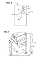
- FIG 6 a diagram showing engagement of the latch protrusion 40 with the contact carrier 4.
- a coil spring 46 biases the latch protrusion 40 against the contact carrier 4.
- the coil spring 46 may extend through a latch cavity 50 defined by four posts 52 and an end plate 54 having an aperture 56.
- a latch cover 58 also comprising a polymeric substance may be disposed over and cover the latch 36.
- the latch cover 58 may comprise a stop plate 60 and an elongated slot 62 wherethrough the latch member 42 may movably extend.
- a pair of mounting flanges 64 may be configured to engage the grooves 34 of the support structures 28 (see Figure 4 ) when mounted thereto.
- Figure 9 diagrammatically illustrates a sensor 66 that is configured to sense the presence or absence of the latch member 42.
- the sensor 66 is a transmissive optosensor such as that sold by the King Bright (Part no. KRA 01) company of China.
- the sensor 66 has a cavity (not numbered) wherein the presence of the latch member 42 may be determined. The presence of the latch member 42 is accomplished by interrupting the passage of light energy from one side of the cavity to another.
- a method of sensing position of a contact carrier of a contact module is shown generally at 100.
- the method comprising, as shown at 102, biasing a latch into engagement with the contact carrier and, as shown at 104, sensing the presence or absence of the latch at a particular location.
Landscapes
- Switches Operated By Changes In Physical Conditions (AREA)
- Control Of Conveyors (AREA)
- Electrophonic Musical Instruments (AREA)
- Train Traffic Observation, Control, And Security (AREA)
Applications Claiming Priority (1)
| Application Number | Priority Date | Filing Date | Title |
|---|---|---|---|
| US11/867,769 US7655876B2 (en) | 2007-10-05 | 2007-10-05 | Method and apparatus for sensing contact position |
Publications (3)
| Publication Number | Publication Date |
|---|---|
| EP2045828A2 true EP2045828A2 (de) | 2009-04-08 |
| EP2045828A3 EP2045828A3 (de) | 2012-12-12 |
| EP2045828B1 EP2045828B1 (de) | 2015-06-17 |
Family
ID=40120303
Family Applications (1)
| Application Number | Title | Priority Date | Filing Date |
|---|---|---|---|
| EP08164666.3A Active EP2045828B1 (de) | 2007-10-05 | 2008-09-19 | Verfahren und Vorrichtung zur Erfassung der Kontaktposition |
Country Status (3)
| Country | Link |
|---|---|
| US (1) | US7655876B2 (de) |
| EP (1) | EP2045828B1 (de) |
| CN (1) | CN101414515B (de) |
Families Citing this family (5)
| Publication number | Priority date | Publication date | Assignee | Title |
|---|---|---|---|---|
| JP4278699B1 (ja) * | 2008-03-27 | 2009-06-17 | Tdk株式会社 | 密閉容器及び該密閉容器の蓋開閉システム、ウエハ搬送システム、及び密閉容器の蓋閉鎖方法 |
| JP2011529584A (ja) * | 2008-07-28 | 2011-12-08 | ピクセル チー コーポレイション | 3モード液晶ディスプレイ |
| US8670004B2 (en) * | 2009-03-16 | 2014-03-11 | Pixel Qi Corporation | Driving liquid crystal displays |
| FR3010584B1 (fr) * | 2013-09-12 | 2015-10-02 | Schneider Electric Ind Sas | Appareil auxiliaire pour disjoncteur electrique, systeme electrique comportant un disjoncteur et un tel appareil auxiliaire et procede de determination d'une cause de l'ouverture du disjoncteur a l'aide d'un tel appareil auxiliaire |
| CN208938885U (zh) * | 2018-10-12 | 2019-06-04 | 伊顿电气有限公司 | 接触器 |
Citations (1)
| Publication number | Priority date | Publication date | Assignee | Title |
|---|---|---|---|---|
| US5907267A (en) | 1997-05-06 | 1999-05-25 | Eaton Corporation | Photoelectric auxiliary switch for electromagnetic contactor |
Family Cites Families (11)
| Publication number | Priority date | Publication date | Assignee | Title |
|---|---|---|---|---|
| US3916133A (en) * | 1974-04-22 | 1975-10-28 | Allen Bradley Co | Optical indicator for enclosed operating mechanism |
| FR2388391A1 (fr) * | 1977-04-22 | 1978-11-17 | Merlin Gerin | Dispositif de signalisation pour poste blinde haute-tension |
| FI84766C (fi) * | 1990-06-26 | 1992-01-10 | Abb Stroemberg Kojeet Oy | Elektronisk hjaelpkontakt foer kontaktor. |
| US5198789A (en) * | 1991-07-25 | 1993-03-30 | Westinghouse Electric Corp. | Logic level electrical interlock device |
| FR2701617B1 (fr) * | 1993-02-16 | 1995-04-14 | Merlin Gerin | Disjoncteur à télécommande et à fonction de sectionnement. |
| US6313418B1 (en) * | 1996-01-12 | 2001-11-06 | Breed Automotive Technology, Inc. | Glass encapsulated extended dwell shock sensor |
| US5954413A (en) * | 1996-08-09 | 1999-09-21 | Myers Industries, Inc. | Modular storage system |
| US6380501B1 (en) * | 2000-08-17 | 2002-04-30 | General Electric Company | Trip indication capability for circuit breaker remote handle operator |
| US6433290B1 (en) * | 2001-01-11 | 2002-08-13 | Eaton Corporation | Trip indicator including latch for a circuit breaker |
| US7532096B2 (en) * | 2005-10-19 | 2009-05-12 | Eaton Corporation | Auxiliary switch including movable slider member and electric power apparatus employing same |
| CN100498997C (zh) * | 2007-04-16 | 2009-06-10 | 上海万松电气设备有限公司 | 双电源切换装置断路器工作位置的定位方法和装置 |
-
2007
- 2007-10-05 US US11/867,769 patent/US7655876B2/en active Active
-
2008
- 2008-09-19 EP EP08164666.3A patent/EP2045828B1/de active Active
- 2008-10-06 CN CN200810169644.8A patent/CN101414515B/zh active Active
Patent Citations (1)
| Publication number | Priority date | Publication date | Assignee | Title |
|---|---|---|---|---|
| US5907267A (en) | 1997-05-06 | 1999-05-25 | Eaton Corporation | Photoelectric auxiliary switch for electromagnetic contactor |
Also Published As
| Publication number | Publication date |
|---|---|
| EP2045828A3 (de) | 2012-12-12 |
| CN101414515B (zh) | 2014-08-20 |
| CN101414515A (zh) | 2009-04-22 |
| US7655876B2 (en) | 2010-02-02 |
| US20090090604A1 (en) | 2009-04-09 |
| EP2045828B1 (de) | 2015-06-17 |
Similar Documents
| Publication | Publication Date | Title |
|---|---|---|
| EP2045828B1 (de) | Verfahren und Vorrichtung zur Erfassung der Kontaktposition | |
| US9318280B2 (en) | Contactless switch | |
| JP4058446B2 (ja) | 薬剤ポンプ用カセット識別システムおよび方法 | |
| CN105570444A (zh) | 换挡装置 | |
| CN101858756A (zh) | 将指针返回到原点的方法 | |
| CA2576934A1 (en) | Printing material container | |
| WO2008130469A1 (en) | Interconnect detection system | |
| CN103688006A (zh) | 具有用于检测开门器的可移动组件的位置的装置的开门器 | |
| JP4858244B2 (ja) | 分電盤 | |
| KR20060008071A (ko) | 스위치 조립체 | |
| CN107204245B (zh) | 蓄电池运行的手引导式工作器械的电子机械的功能单元 | |
| KR20120082411A (ko) | 전자기 스위칭 디바이스를 위한 수명 모니터링을 갖는 부가 모듈, 및 연관된 방법 | |
| JP2015507174A (ja) | 共通のハウジング内に変位センサと圧力センサを備えるセンサモジュール | |
| SE0300794D0 (sv) | Sätt och givaranordning för avståndsmätning | |
| JP4720159B2 (ja) | 液面検出装置 | |
| CN120389741A (zh) | 一种多功能微动开关及其运用方法 | |
| CN219659697U (zh) | 一种角磨机及园林工具的防误接通直流集成开关 | |
| JP5914250B2 (ja) | On/off検出型バックルスイッチ | |
| AU2008314543A1 (en) | Aperture assembly for use with a photosensor system and a securing mechanism for the aperture assembly | |
| US20080084022A1 (en) | Bill Stacker Detection Apparatus | |
| EP0873592B1 (de) | Lineare betätigungseinrichtung für optischen schalter | |
| JP7038349B2 (ja) | スイッチ装置及びその生産方法 | |
| CN117073989B (zh) | 一种汞灯光源检测组件及uv固胶机 | |
| US7317170B2 (en) | Electronic function relay | |
| US20090262903A1 (en) | Butt-set with waterproof and ambidextrous switch |
Legal Events
| Date | Code | Title | Description |
|---|---|---|---|
| PUAI | Public reference made under article 153(3) epc to a published international application that has entered the european phase |
Free format text: ORIGINAL CODE: 0009012 |
|
| AK | Designated contracting states |
Kind code of ref document: A2 Designated state(s): AT BE BG CH CY CZ DE DK EE ES FI FR GB GR HR HU IE IS IT LI LT LU LV MC MT NL NO PL PT RO SE SI SK TR |
|
| AX | Request for extension of the european patent |
Extension state: AL BA MK RS |
|
| PUAL | Search report despatched |
Free format text: ORIGINAL CODE: 0009013 |
|
| AK | Designated contracting states |
Kind code of ref document: A3 Designated state(s): AT BE BG CH CY CZ DE DK EE ES FI FR GB GR HR HU IE IS IT LI LT LU LV MC MT NL NO PL PT RO SE SI SK TR |
|
| AX | Request for extension of the european patent |
Extension state: AL BA MK RS |
|
| RIC1 | Information provided on ipc code assigned before grant |
Ipc: H01H 71/46 20060101AFI20121107BHEP Ipc: H01H 9/16 20060101ALI20121107BHEP |
|
| 17P | Request for examination filed |
Effective date: 20130612 |
|
| RBV | Designated contracting states (corrected) |
Designated state(s): AT BE BG CH CY CZ DE DK EE ES FI FR GB GR HR HU IE IS IT LI LT LU LV MC MT NL NO PL PT RO SE SI SK TR |
|
| AKX | Designation fees paid |
Designated state(s): DE ES FR GB IT |
|
| 17Q | First examination report despatched |
Effective date: 20131217 |
|
| GRAP | Despatch of communication of intention to grant a patent |
Free format text: ORIGINAL CODE: EPIDOSNIGR1 |
|
| INTG | Intention to grant announced |
Effective date: 20150410 |
|
| GRAS | Grant fee paid |
Free format text: ORIGINAL CODE: EPIDOSNIGR3 |
|
| GRAA | (expected) grant |
Free format text: ORIGINAL CODE: 0009210 |
|
| AK | Designated contracting states |
Kind code of ref document: B1 Designated state(s): DE ES FR GB IT |
|
| REG | Reference to a national code |
Ref country code: GB Ref legal event code: FG4D |
|
| REG | Reference to a national code |
Ref country code: DE Ref legal event code: R096 Ref document number: 602008038577 Country of ref document: DE |
|
| PG25 | Lapsed in a contracting state [announced via postgrant information from national office to epo] |
Ref country code: ES Free format text: LAPSE BECAUSE OF FAILURE TO SUBMIT A TRANSLATION OF THE DESCRIPTION OR TO PAY THE FEE WITHIN THE PRESCRIBED TIME-LIMIT Effective date: 20150617 |
|
| REG | Reference to a national code |
Ref country code: DE Ref legal event code: R097 Ref document number: 602008038577 Country of ref document: DE |
|
| PLBE | No opposition filed within time limit |
Free format text: ORIGINAL CODE: 0009261 |
|
| STAA | Information on the status of an ep patent application or granted ep patent |
Free format text: STATUS: NO OPPOSITION FILED WITHIN TIME LIMIT |
|
| PG25 | Lapsed in a contracting state [announced via postgrant information from national office to epo] |
Ref country code: IT Free format text: LAPSE BECAUSE OF FAILURE TO SUBMIT A TRANSLATION OF THE DESCRIPTION OR TO PAY THE FEE WITHIN THE PRESCRIBED TIME-LIMIT Effective date: 20150617 |
|
| 26N | No opposition filed |
Effective date: 20160318 |
|
| GBPC | Gb: european patent ceased through non-payment of renewal fee |
Effective date: 20150919 |
|
| REG | Reference to a national code |
Ref country code: FR Ref legal event code: ST Effective date: 20160531 |
|
| PG25 | Lapsed in a contracting state [announced via postgrant information from national office to epo] |
Ref country code: GB Free format text: LAPSE BECAUSE OF NON-PAYMENT OF DUE FEES Effective date: 20150919 |
|
| PG25 | Lapsed in a contracting state [announced via postgrant information from national office to epo] |
Ref country code: FR Free format text: LAPSE BECAUSE OF NON-PAYMENT OF DUE FEES Effective date: 20150930 |
|
| REG | Reference to a national code |
Ref country code: DE Ref legal event code: R081 Ref document number: 602008038577 Country of ref document: DE Owner name: ABB SCHWEIZ AG, CH Free format text: FORMER OWNER: GENERAL ELECTRIC COMPANY, SCHENECTADY, N.Y., US Ref country code: DE Ref legal event code: R081 Ref document number: 602008038577 Country of ref document: DE Owner name: ABB SCHWEIZ AG, CH Free format text: FORMER OWNER: GENERAL ELECTRIC COMPANY, SCHENECTADY, NY, US |
|
| REG | Reference to a national code |
Ref country code: DE Ref legal event code: R082 Ref document number: 602008038577 Country of ref document: DE Representative=s name: ZIMMERMANN & PARTNER PATENTANWAELTE MBB, DE |
|
| PGFP | Annual fee paid to national office [announced via postgrant information from national office to epo] |
Ref country code: DE Payment date: 20250919 Year of fee payment: 18 |