EP2045829A2 - Mécanisme de bras de contact pour disjoncteur - Google Patents
Mécanisme de bras de contact pour disjoncteur Download PDFInfo
- Publication number
- EP2045829A2 EP2045829A2 EP08164550A EP08164550A EP2045829A2 EP 2045829 A2 EP2045829 A2 EP 2045829A2 EP 08164550 A EP08164550 A EP 08164550A EP 08164550 A EP08164550 A EP 08164550A EP 2045829 A2 EP2045829 A2 EP 2045829A2
- Authority
- EP
- European Patent Office
- Prior art keywords
- pair
- linkages
- circuit breaker
- contact arm
- coupled
- Prior art date
- Legal status (The legal status is an assumption and is not a legal conclusion. Google has not performed a legal analysis and makes no representation as to the accuracy of the status listed.)
- Granted
Links
- 230000007246 mechanism Effects 0.000 title claims abstract description 115
- 230000005405 multipole Effects 0.000 claims description 13
- 230000008878 coupling Effects 0.000 claims description 7
- 238000010168 coupling process Methods 0.000 claims description 7
- 238000005859 coupling reaction Methods 0.000 claims description 7
- 230000004044 response Effects 0.000 claims description 5
- 230000006835 compression Effects 0.000 description 6
- 238000007906 compression Methods 0.000 description 6
- 239000004020 conductor Substances 0.000 description 6
- 239000000969 carrier Substances 0.000 description 2
- 230000005611 electricity Effects 0.000 description 2
- 239000011810 insulating material Substances 0.000 description 2
- 239000000463 material Substances 0.000 description 2
- KXGFMDJXCMQABM-UHFFFAOYSA-N 2-methoxy-6-methylphenol Chemical compound [CH]OC1=CC=CC([CH])=C1O KXGFMDJXCMQABM-UHFFFAOYSA-N 0.000 description 1
- RYGMFSIKBFXOCR-UHFFFAOYSA-N Copper Chemical compound [Cu] RYGMFSIKBFXOCR-UHFFFAOYSA-N 0.000 description 1
- 229910000831 Steel Inorganic materials 0.000 description 1
- XAGFODPZIPBFFR-UHFFFAOYSA-N aluminium Chemical compound [Al] XAGFODPZIPBFFR-UHFFFAOYSA-N 0.000 description 1
- 229910052782 aluminium Inorganic materials 0.000 description 1
- 230000004888 barrier function Effects 0.000 description 1
- 239000002131 composite material Substances 0.000 description 1
- 229910052802 copper Inorganic materials 0.000 description 1
- 239000010949 copper Substances 0.000 description 1
- 238000010292 electrical insulation Methods 0.000 description 1
- 230000006870 function Effects 0.000 description 1
- 230000003993 interaction Effects 0.000 description 1
- 238000000034 method Methods 0.000 description 1
- 239000005011 phenolic resin Substances 0.000 description 1
- 229920001568 phenolic resin Polymers 0.000 description 1
- 229920000728 polyester Polymers 0.000 description 1
- UYKQQBUWKSHMIM-UHFFFAOYSA-N silver tungsten Chemical compound [Ag][W][W] UYKQQBUWKSHMIM-UHFFFAOYSA-N 0.000 description 1
- 239000010959 steel Substances 0.000 description 1
- 229920001187 thermosetting polymer Polymers 0.000 description 1
Images




Classifications
-
- H—ELECTRICITY
- H01—ELECTRIC ELEMENTS
- H01H—ELECTRIC SWITCHES; RELAYS; SELECTORS; EMERGENCY PROTECTIVE DEVICES
- H01H71/00—Details of the protective switches or relays covered by groups H01H73/00 - H01H83/00
-
- H—ELECTRICITY
- H01—ELECTRIC ELEMENTS
- H01H—ELECTRIC SWITCHES; RELAYS; SELECTORS; EMERGENCY PROTECTIVE DEVICES
- H01H77/00—Protective overload circuit-breaking switches operated by excess current and requiring separate action for resetting
- H01H77/02—Protective overload circuit-breaking switches operated by excess current and requiring separate action for resetting in which the excess current itself provides the energy for opening the contacts, and having a separate reset mechanism
- H01H77/10—Protective overload circuit-breaking switches operated by excess current and requiring separate action for resetting in which the excess current itself provides the energy for opening the contacts, and having a separate reset mechanism with electrodynamic opening
- H01H77/102—Protective overload circuit-breaking switches operated by excess current and requiring separate action for resetting in which the excess current itself provides the energy for opening the contacts, and having a separate reset mechanism with electrodynamic opening characterised by special mounting of contact arm, allowing blow-off movement
- H01H77/104—Protective overload circuit-breaking switches operated by excess current and requiring separate action for resetting in which the excess current itself provides the energy for opening the contacts, and having a separate reset mechanism with electrodynamic opening characterised by special mounting of contact arm, allowing blow-off movement with a stable blow-off position
-
- H—ELECTRICITY
- H01—ELECTRIC ELEMENTS
- H01H—ELECTRIC SWITCHES; RELAYS; SELECTORS; EMERGENCY PROTECTIVE DEVICES
- H01H71/00—Details of the protective switches or relays covered by groups H01H73/00 - H01H83/00
- H01H71/10—Operating or release mechanisms
- H01H71/12—Automatic release mechanisms with or without manual release
- H01H71/24—Electromagnetic mechanisms
- H01H71/2418—Electromagnetic mechanisms combined with an electrodynamic current limiting mechanism
- H01H2071/2427—Electromagnetic mechanisms combined with an electrodynamic current limiting mechanism with blow-off movement tripping mechanism, e.g. electrodynamic effect on contacts trips the traditional trip device before it can unlatch the spring mechanism by itself
Definitions
- the subject matter disclosed herein relates to a mechanism for a circuit breaker.
- the subject matter disclosed herein relates to a mechanism coupled to a contact arm to provide current limiting functionality by reducing the opening time.
- Air circuit breakers are commonly used in electrical distribution systems.
- a typical air circuit breaker comprises an assembly of components for connecting an electrical power source to a consumer of electrical power called a load.
- the components are referred to as a main contact assembly.
- a main contact is typically either opened, interrupting a path for power to travel from the source to the load, or closed, providing a path for power to travel from the source to the load.
- the force necessary to open or close the main contact assembly is provided by an arrangement of compression springs. When the compression springs discharge, they exert a force that provides the energy needed to open or close the main contacts. Compression springs that provide a force to close the main contacts are often called closing springs. Compression springs that provide a force to open the main contacts are often referred to as contact springs.
- the mechanism for controlling the compression springs comprises a configuration of mechanical linkages between a latching shaft and an actuation device.
- the actuation device may be manually or electrically operated.
- An electrically operated actuation device generally operates when a particular electrical condition is sensed, for example, over-current or short-circuit conditions.
- the actuation device within the circuit breaker typically imparts a force onto a linkage assembly.
- the linkage assembly then translates the force from the actuation device into a rotational force exerted on the latching shaft.
- the latching shaft then rotates. This rotation is translated through the mechanical linkages to unlatch or activate either the closing springs or the contact springs.
- a second latching shaft is mechanically linked to the contact springs called the tripping shaft.
- the linkage assembly acts as a lever converting a linear force from the actuation device to a rotational force on the latching shaft.
- a circuit breaker having a contact structure movable between a closed and an open position.
- a first mechanism is operably coupled to the contact structure where the mechanism is movable between an open and a closed position.
- a second mechanism is operably coupled between the first mechanism and the contact structure.
- the second mechanism includes a first linkage pair having first and second links operably coupled to the contact structure.
- the second mechanism further includes a second linkage pair having third and fourth links operably coupled to the first mechanism.
- a first spring couples the first linkage pair and a second spring couples the second linkage pair.
- a mechanism for a circuit breaker contact arm having a first carrier.
- the mechanism further includes a first pair of linkages coupled to each other by a first spring where each of the first pair of linkages is pivotally coupled to the first carrier.
- a second pair of linkages is coupled to each other by a second spring. Each of the second pair of linkages is pivotally coupled to the first pair of linkages.
- a second carrier is pivotally coupled to the second pair of linkages.
- a multi-pole circuit breaker having a mechanism movable between a first and second position.
- the multi-pole circuit breaker further has a first and second contact arm with each of the contact arms being movable between a closed and a blown-open position.
- a first and second contact mechanisms is associated with one of the contact arm. Each contact mechanism operably couples the associated contact arm and the mechanism.
- Each of the contact mechanisms further includes a first carrier connected to the contact arm.
- a first pair of linkages is coupled to each other by a first spring and pivotally coupled to the first carrier.
- a second pair of linkages is coupled to each other by a second spring and is pivotally coupled to the first pair of linkages.
- a second carrier is pivotally coupled to the second pair of linkages and is pivotally coupled to the mechanism.
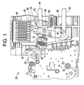
- FIGURE 1 illustrates a circuit breaker 20 in the closed position.
- the circuit breaker 20 includes a main mechanism (not shown) that is coupled to a lay shaft assembly 22.
- the lay shaft assembly 22 rotates in response to the main mechanism being moved between an on and off position.
- the lay shaft assembly is coupled to a contact arm mechanism 24 through a pin 26.
- the contact arm mechanism 24 as illustrated in Figure 1 is in a locked position and transfers the energy from the main mechanism that is necessary to open and close a contact arm assembly 28.
- the contact arm assembly 28 is mounted in the circuit breaker 20 to pivot about a pin 30 to move between a closed, an open and a blown-open position.
- the contact arm assembly 28 is illustrated in the exemplary embodiment as a single component.
- the contact arm 32 may be comprised of multiple contact arms each coupled to the contact arm mechanism 24.
- the exemplary embodiment illustrates the circuit breaker 20 have a single contact arm or what is commonly referred to as a "pole.”
- Each pole of a circuit breaker carries electrical current for a single electrical phase.
- the circuit breaker will have several poles, typically three, each carrying a different phase of electricity through the circuit breaker 20.
- Each of the poles is individually connected to the lay shaft assembly 22 through a separate contact arm assembly 24.
- the contact arm assembly 28 includes an arm 32 having a movable contact 34 and an arcing contact 36 mounted to one end.
- a flexible, electrically conductive strap 38 made from braided copper cable for example, is attached to the opposite end.
- the strap 38 electrically couples the contact arm 32 to a conductor 40 that allows electrical current to flow through the circuit breaker 20.
- the electrical current flows through the contact arm assembly 32 and exits via movable contact 34.
- the current then passes through stationary contact 42 and into conductor 44 where it is transmitted to the load.
- the contacts 34, 42 are typically made from a silver tungsten composite to minimize resistance.
- Another arcing contact 46 is mounted to the conductor 44.
- the arcing contacts 36, 46 assist the circuit breaker in moving any electrical arc formed when the contact arm is opened into an arc chute 48.
- a compression spring 50 is mounted to the circuit breaker 20 to exert a force on the bottom of the contact arm assembly 32 and assist with the opening of the contact arm.
- the operator may desire to remove electrical power from a circuit.
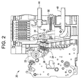
- the main mechanism is activated, by an off push button for example, causing the lay shaft assembly 22 to rotate to an open position as illustrated in Figure 2 .
- the contact arm assembly 24 remains in a locked position.
- the rotational movement of the lay shaft assembly is translated into motion of the contact arm mechanism 24 causing the contact arm assembly 28 to rotate about pivot 30.
- This rotation by the contact arm assembly 28 results in the movable contact 34 separating from the stationary contact 42 and the halting of electrical current flow.
- the operator reactivates the main mechanism, by moving a closing push button for example, causing the lay shaft assembly 22 to rotate back to the position illustrated in Figure 1 .
- circuit breaker 20 may carry 400 - 5000 A of electricity at 690V. Under short circuit conditions, the current levels may exceed more than 100kA depending upon the facility in which the circuit breaker 20 is installed. These high levels of current are undesirable and the operator will typically desire to limit the amount of current that flows through circuit breaker 20 under these conditions. During these conditions, due to the geometry of the current path through the circuit breaker 20, a large amount of magnetic force is generated between the contact arm assembly 28 and the conductor 44.
- the contact arm assembly 28 is arranged such that when the magnetic force between the conductor 44 and the contact arm assembly 28 reaches a predefined level the contact arm assembly starts to rotate independent from the main mechanism.
- the contact arm assembly rotation may initiate at the magnetic force level corresponding to 25kA - 100kA and more preferably 50kA.
- the different thresholds at which contact arm assembly 28 blows open will depend on selectivity of the circuit breaker 20 with other downstream feeder breakers (not shown) and the threshold limits are adjustable by varying force exerted by springs 88 of contact arm mechanism 24.
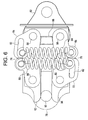
- the contact arm mechanism 24 will move from a locked position shown in Figure 1 , Figure 2 and Figure 6 to an open position illustrated in Figure 3 .
- the contact arm assembly 32 is then rotated towards the open position.
- the rotation of the contact arm assembly 28 causes the movable contact 34 to separate from the stationary contact 42. Any electrical arc generated between the contacts 34, 42 is transferred via arcing contacts 36, 46 to the arc chute 48 where the energy from the electrical arc is dissipated.
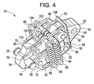
- the contact arm assembly 28 has a first carrier 52 that couples the contact arm mechanism 24 to the contact arm assembly 28.
- the contact arn mechanism 24 has a second carrier 78 that couples the contact arm mechanism to the lay shaft assembly 22.
- Plate 53 is attached to the carrier 52 to provide an electrical insulation barrier between the contact arm assembly 28 and the linkages in the contact arm mechanism 24.
- the carrier plates 52, 78 may be made from any suitable insulating material, phenolic resin or thermoset polyester plastic for example, a pair of links 54, 56 are coupled to the carrier 52 by pins 58.
- the link 54 includes a slot 60 that captures a pin 62.
- the links may be made from any suitable material, including but not limited to steel, aluminum or plastic.
- a second pin 66 is coupled to the link 56.
- the pins 62, 66 capture an extension spring 64 to couple the links together.
- the projection 68 helps in avoiding the collapsing of flexible links.
- a second pair of links 70, 72 is coupled to the links 54, 56 by pins 74, 76 ( Figure 6 ) respectively.
- a slot 82 in link 72 captures pin 84 and another pin 86, attached to link 70, allows a second spring 88 to couple the links 70, 72.
- the links 70, 72 are coupled to a second carrier 78 by pins 80.
- the second carrier 78 may be made from any suitable material. In the exemplary embodiment, the second carrier 78 is made from the same insulating material same as carrier 52.
- a pin 26 couples the second carrier to the lay shaft assembly 22.
- Link 56 includes a surface 108 that contacts the pin 84 while the contact arm mechanism 24 is in the locked position.
- a pair of plate guides 92, 94 is coupled between pins 80, 58. Each plate guide 92, 94 includes a slot 96 that allows the plate guides 92, 94 to rotate as the contact arm mechanism 24 moves between a locked and open position.
- a third pair, 98, 99 and fourth pair 100, 101 of links are arranged in an identical, but mirror, manner on the opposite sides of the carriers 52, 78.
- the linkage pairs are separated by the thickness of the body 108, 110 of the carriers 52, 78 respectively.
- Extension spring 102 couples the third linkage pair 98,99 and extension spring 104 couples the fourth linkage pair 100, 101.
- a second plate 106 is positioned between the third and fourth linkage pairs includes a projection similar to projection 68 to separate the links and maintain them in the correct position.
- the first pair of linkages 54, 56 and the third pair of linkages 98, 99 are coupled together by pins 62, 66 respectively.
- each half of the contact arm mechanism assembly 24 is a mirror image of the other and that while the operation of the contact arm mechanism assembly 24 may be described herein with respect to one of the sides, first linkage pair 54, 56 and second linkage pair 70, 72 for example, the description is also describing the operation of the opposite side of contact arm mechanism 24.
- the contact arm mechanism 24 is in a locked position, as illustrated in Figure 4 and Figure 6 . While in the locked position, the contact arm mechanism 24 moves, more or less, as a single rigid linkage between the main mechanism and the contact arm assembly 32. This allows the main mechanism to open and close the contact arm assembly 32 without changing the position of the components in contact arm mechanism 24 relative to each other. However, during a short-circuit condition, as discussed above, the lay shaft assembly 22 remains in a closed position, while the magnetic force bias' the contact arm 32 towards the open position.
- the contact arm assembly 32 will start to rotate allowing the movable contact 34 to separate from the stationary contact 42.
- the contact arm assembly 32 will continue to open until the pins 62, 84 reach the ends of the link slots. This position, commonly known as the "blown-open" position, is illustrated in Figure 3 .
- Allowing the contact arm assembly 32 to separate from the stationary contact 42 without the assistance of the main mechanism provide advantages in the operation of the circuit breaker 20.
- This opening operation (“blow-open operation”) allows the minimum current through the circuit breaker for an existing fault level in the system, and thus the fault experienced by the protected load, to be limited since the contact arm mechanism 24 can react to the undesired electrical condition faster than the main mechanism.
- the contract arm mechanism will allow the contact arm assembly 32 to separate in 8 -10 milliseconds versus 30 milliseconds for the main mechanism.
- the main mechanism will move to the open position after the blow-open position is reached, allowing the other poles associated with the circuit breaker to open.
- the level at which the blow-open operation is activated is a function of the force generated by the springs 64, 88, 102, 104.
- the operator may choose the level at which the circuit breaker 20 will initiate the blow-open operation by changing the springs 64, 88, 102, 104.
- a single circuit breaker may be easily reconfigured for use in many different applications through the changing of a single component.
- the operator may desire for other circuit breakers (not shown) that are down stream from the circuit breaker 20 to interrupt the electrical current in the event of a short-circuit condition. This may be accomplished by coordinating the blow-open level of circuit breaker 20 with those down-stream circuit breakers.
- the operator can provide the appropriate levels of protection to portions of the protected load, and while still maintaining protection in the event of a larger short-circuit condition.
Landscapes
- Physics & Mathematics (AREA)
- Electromagnetism (AREA)
- Breakers (AREA)
- Driving Mechanisms And Operating Circuits Of Arc-Extinguishing High-Tension Switches (AREA)
Applications Claiming Priority (1)
| Application Number | Priority Date | Filing Date | Title |
|---|---|---|---|
| US11/867,352 US7566840B2 (en) | 2007-10-04 | 2007-10-04 | Contact arm mechanism for circuit breaker |
Publications (3)
| Publication Number | Publication Date |
|---|---|
| EP2045829A2 true EP2045829A2 (fr) | 2009-04-08 |
| EP2045829A3 EP2045829A3 (fr) | 2011-08-17 |
| EP2045829B1 EP2045829B1 (fr) | 2013-08-14 |
Family
ID=40239742
Family Applications (1)
| Application Number | Title | Priority Date | Filing Date |
|---|---|---|---|
| EP08164550.9A Not-in-force EP2045829B1 (fr) | 2007-10-04 | 2008-09-18 | Mécanisme de bras de contact pour disjoncteur |
Country Status (7)
| Country | Link |
|---|---|
| US (1) | US7566840B2 (fr) |
| EP (1) | EP2045829B1 (fr) |
| JP (1) | JP2009094065A (fr) |
| KR (1) | KR20090034769A (fr) |
| CN (1) | CN101404232B (fr) |
| CA (1) | CA2639606A1 (fr) |
| MX (1) | MX2008012733A (fr) |
Cited By (1)
| Publication number | Priority date | Publication date | Assignee | Title |
|---|---|---|---|---|
| GB2543812A (en) * | 2015-10-30 | 2017-05-03 | Long Men Tech Co Ltd | High and ultra-high voltage circuit breaking system |
Families Citing this family (11)
| Publication number | Priority date | Publication date | Assignee | Title |
|---|---|---|---|---|
| FI121155B (fi) * | 2008-06-19 | 2010-07-30 | Abb Oy | Ohjainyksikkö kytkinlaitetta varten |
| FI121154B (fi) * | 2008-06-19 | 2010-07-30 | Abb Oy | Ohjainyksikkö kytkinlaitetta varten |
| FI121153B (fi) * | 2008-06-19 | 2010-07-30 | Abb Oy | Laukaisinkokoonpano kytkinlaitetta varten |
| FR2956922B1 (fr) * | 2010-03-01 | 2012-08-24 | Schneider Electric Ind Sas | Dispositif de coupure |
| GB201200331D0 (en) * | 2012-01-09 | 2012-02-22 | Dialight Europ Ltd | Improvements in switching contactors (II) |
| US9406470B2 (en) * | 2014-02-18 | 2016-08-02 | General Electric Company | Tri-stable flexure mechanism |
| US9349560B2 (en) | 2014-02-20 | 2016-05-24 | General Electric Company | Limiter type air circuit breaker with blow open arrangement |
| US9552950B2 (en) | 2015-06-11 | 2017-01-24 | General Electric Company | Retaining assembly for a circuit breaker contact system |
| US9576753B2 (en) | 2015-06-16 | 2017-02-21 | General Electric Company | Moveable contact arm releases latch plate engagement in a circuit breaker |
| EP3389069B1 (fr) * | 2017-04-11 | 2019-12-11 | Microelettrica Scientifica S.p.A. | Disjoncteur amélioré pour des applications à courant cc élevé ou à tension cc élevée, par exemple des applications industrielles et/ou ferroviaires |
| CN108766845B (zh) * | 2018-08-20 | 2024-03-19 | 厦门大恒科技有限公司 | 一种液压电磁铁结构以及断路器 |
Family Cites Families (20)
| Publication number | Priority date | Publication date | Assignee | Title |
|---|---|---|---|---|
| US3533027A (en) * | 1967-12-29 | 1970-10-06 | Terasaki Denki Sangyo Kk | Contact assembly of circuit interrupter |
| IT1006446B (it) * | 1974-04-12 | 1976-09-30 | Sace Spa | Interruttore elettrico limitatore di corrente esente da rimbalzi in fase di apertura |
| US4761524A (en) * | 1987-05-26 | 1988-08-02 | Electrical Equipment, Inc. | Switch operating mechanism |
| DE3938207A1 (de) * | 1989-11-17 | 1991-05-23 | Reinhausen Maschf Scheubeck | Kraftspeicherantrieb fuer lastumschalter von stufenschaltern in stufentransformatoren |
| DE4034126C1 (fr) * | 1990-10-26 | 1992-03-05 | Maschinenfabrik Reinhausen Gmbh, 8400 Regensburg, De | |
| IT1292453B1 (it) * | 1997-07-02 | 1999-02-08 | Aeg Niederspannungstech Gmbh | Gruppo rotante di contatti per interrutttori di alta portata |
| FR2781921B1 (fr) * | 1998-07-29 | 2000-09-15 | Schneider Electric Ind Sa | Disjoncteur a tenue electrodynamique et pouvoir de coupure eleves |
| EP1098343B1 (fr) * | 1999-11-03 | 2005-09-21 | AEG Niederspannungstechnik GmbH & Co. KG | Dispositif a contact tournant pour disjoncteur |
| US6586693B2 (en) * | 2000-03-17 | 2003-07-01 | General Electric Company | Self compensating latch arrangement |
| DE10054383A1 (de) * | 2000-10-27 | 2002-05-08 | Siemens Ag | Strombegrenzender Niederspannungs-Leistungsschalter |
| US6376788B1 (en) * | 2001-01-08 | 2002-04-23 | Eaton Corporation | Magnetically collapsible toggle linkage for electrical switching apparatus |
| US6507256B1 (en) * | 2001-08-17 | 2003-01-14 | General Electric Company | Auxiliary magnetic trip system |
| ITMI20012325A1 (it) * | 2001-11-06 | 2003-05-06 | Abb Service Srl | Interruttore di bassa tensione |
| CN1224070C (zh) * | 2001-11-29 | 2005-10-19 | 陈臣明 | 带斥力机构的限流装置 |
| US6437670B1 (en) * | 2002-02-12 | 2002-08-20 | General Electric Company | Magnetic release system for a circuit breaker |
| US6940032B2 (en) * | 2004-01-12 | 2005-09-06 | General Electric Company | Method and apparatus for achieving three positions |
| US7105764B2 (en) * | 2005-01-13 | 2006-09-12 | Eaton Corporation | Monolithic stationary conductor and current limiting power switch incorporating same |
| US6977568B1 (en) * | 2005-01-13 | 2005-12-20 | Eaton Corporation | Blow open moving contact assembly for electric power switching apparatus with a very high current interruption rating |
| US7189935B1 (en) * | 2005-12-08 | 2007-03-13 | General Electric Company | Contact arm apparatus and method of assembly thereof |
| KR100771918B1 (ko) * | 2006-10-17 | 2007-11-01 | 엘에스산전 주식회사 | 기중차단기의 개폐기구 |
-
2007
- 2007-10-04 US US11/867,352 patent/US7566840B2/en active Active
-
2008
- 2008-09-18 EP EP08164550.9A patent/EP2045829B1/fr not_active Not-in-force
- 2008-09-18 CA CA002639606A patent/CA2639606A1/fr not_active Abandoned
- 2008-10-01 JP JP2008255869A patent/JP2009094065A/ja not_active Withdrawn
- 2008-10-02 MX MX2008012733A patent/MX2008012733A/es not_active Application Discontinuation
- 2008-10-02 KR KR1020080097146A patent/KR20090034769A/ko not_active Withdrawn
- 2008-10-06 CN CN2008101693098A patent/CN101404232B/zh not_active Expired - Fee Related
Non-Patent Citations (1)
| Title |
|---|
| None |
Cited By (2)
| Publication number | Priority date | Publication date | Assignee | Title |
|---|---|---|---|---|
| GB2543812A (en) * | 2015-10-30 | 2017-05-03 | Long Men Tech Co Ltd | High and ultra-high voltage circuit breaking system |
| GB2543812B (en) * | 2015-10-30 | 2020-01-01 | Long Men Tech Co Ltd | High and ultra-high voltage circuit breaking system |
Also Published As
| Publication number | Publication date |
|---|---|
| CA2639606A1 (fr) | 2009-04-04 |
| KR20090034769A (ko) | 2009-04-08 |
| JP2009094065A (ja) | 2009-04-30 |
| CN101404232A (zh) | 2009-04-08 |
| MX2008012733A (es) | 2009-05-12 |
| EP2045829B1 (fr) | 2013-08-14 |
| US20090091407A1 (en) | 2009-04-09 |
| EP2045829A3 (fr) | 2011-08-17 |
| US7566840B2 (en) | 2009-07-28 |
| CN101404232B (zh) | 2013-11-13 |
Similar Documents
| Publication | Publication Date | Title |
|---|---|---|
| US7566840B2 (en) | Contact arm mechanism for circuit breaker | |
| US4489295A (en) | Circuit interrupter with improved electro-mechanical undervoltage release mechanism | |
| CA1130348A (fr) | Circuit rupeur limiteur de courant a mecanisme de commande ameliore | |
| EP2061057B1 (fr) | Système de déclenchement secondaire pour disjoncteur | |
| CA2704408C (fr) | Cliquet inertiel pour contacteur a commutation automatique | |
| US6403909B1 (en) | Trip override for rotary breaker | |
| US8159319B2 (en) | Double-breaking contact system for a low voltage circuit breaker, a molded case circuit breaker comprising the double-breaking contact system, and a method for breaking a circuit | |
| JPS6243027A (ja) | 回路遮断器 | |
| CN102262983B (zh) | 一种转动触头组件 | |
| JPH03145029A (ja) | 回路遮断器 | |
| CA2213671C (fr) | Interrupteur a manoeuvrer par perche isolante | |
| CN101170034A (zh) | 小型断路器 | |
| US5023583A (en) | Circuit breaker contact operating structure | |
| US9412549B2 (en) | Electromagnetically enhanced contact separation in a circuit breaker | |
| US5835002A (en) | Interlock assembly for a manually operated multi-phase fusible switch | |
| EP0204216B1 (fr) | Disjoncteur avec contact à ouverture électrodynamique | |
| EP3107112B1 (fr) | Système de contact d'un disjoncteur, et disjoncteur | |
| US5917390A (en) | Circuit breaker with current limiting contact structure | |
| JP7540415B2 (ja) | 回路遮断器 | |
| CN105990068B (zh) | 分流断路系统 | |
| CN105845494A (zh) | 分流断路系统 | |
| MXPA01002791A (en) | Circuit breaker mechanism tripping cam |
Legal Events
| Date | Code | Title | Description |
|---|---|---|---|
| PUAI | Public reference made under article 153(3) epc to a published international application that has entered the european phase |
Free format text: ORIGINAL CODE: 0009012 |
|
| AK | Designated contracting states |
Kind code of ref document: A2 Designated state(s): AT BE BG CH CY CZ DE DK EE ES FI FR GB GR HR HU IE IS IT LI LT LU LV MC MT NL NO PL PT RO SE SI SK TR |
|
| AX | Request for extension of the european patent |
Extension state: AL BA MK RS |
|
| PUAL | Search report despatched |
Free format text: ORIGINAL CODE: 0009013 |
|
| AK | Designated contracting states |
Kind code of ref document: A3 Designated state(s): AT BE BG CH CY CZ DE DK EE ES FI FR GB GR HR HU IE IS IT LI LT LU LV MC MT NL NO PL PT RO SE SI SK TR |
|
| AX | Request for extension of the european patent |
Extension state: AL BA MK RS |
|
| RIC1 | Information provided on ipc code assigned before grant |
Ipc: H01H 77/10 20060101AFI20110708BHEP |
|
| 17P | Request for examination filed |
Effective date: 20120217 |
|
| AKX | Designation fees paid |
Designated state(s): DE FR GB IT PL |
|
| GRAP | Despatch of communication of intention to grant a patent |
Free format text: ORIGINAL CODE: EPIDOSNIGR1 |
|
| RIN1 | Information on inventor provided before grant (corrected) |
Inventor name: PAI, ARVIND Inventor name: SUDHAKAR, SAPURAM Inventor name: RAORANE, DEEPAK Inventor name: BAVIKAR, KAPIL |
|
| GRAS | Grant fee paid |
Free format text: ORIGINAL CODE: EPIDOSNIGR3 |
|
| GRAA | (expected) grant |
Free format text: ORIGINAL CODE: 0009210 |
|
| AK | Designated contracting states |
Kind code of ref document: B1 Designated state(s): DE FR GB IT PL |
|
| REG | Reference to a national code |
Ref country code: GB Ref legal event code: FG4D |
|
| REG | Reference to a national code |
Ref country code: DE Ref legal event code: R096 Ref document number: 602008026716 Country of ref document: DE Effective date: 20131010 |
|
| PG25 | Lapsed in a contracting state [announced via postgrant information from national office to epo] |
Ref country code: PL Free format text: LAPSE BECAUSE OF FAILURE TO SUBMIT A TRANSLATION OF THE DESCRIPTION OR TO PAY THE FEE WITHIN THE PRESCRIBED TIME-LIMIT Effective date: 20130814 |
|
| PG25 | Lapsed in a contracting state [announced via postgrant information from national office to epo] |
Ref country code: IT Free format text: LAPSE BECAUSE OF FAILURE TO SUBMIT A TRANSLATION OF THE DESCRIPTION OR TO PAY THE FEE WITHIN THE PRESCRIBED TIME-LIMIT Effective date: 20130814 |
|
| PLBE | No opposition filed within time limit |
Free format text: ORIGINAL CODE: 0009261 |
|
| STAA | Information on the status of an ep patent application or granted ep patent |
Free format text: STATUS: NO OPPOSITION FILED WITHIN TIME LIMIT |
|
| REG | Reference to a national code |
Ref country code: DE Ref legal event code: R119 Ref document number: 602008026716 Country of ref document: DE Effective date: 20140401 |
|
| REG | Reference to a national code |
Ref country code: FR Ref legal event code: ST Effective date: 20140530 |
|
| 26N | No opposition filed |
Effective date: 20140515 |
|
| GBPC | Gb: european patent ceased through non-payment of renewal fee |
Effective date: 20131114 |
|
| PG25 | Lapsed in a contracting state [announced via postgrant information from national office to epo] |
Ref country code: DE Free format text: LAPSE BECAUSE OF NON-PAYMENT OF DUE FEES Effective date: 20140401 Ref country code: FR Free format text: LAPSE BECAUSE OF NON-PAYMENT OF DUE FEES Effective date: 20131014 |
|
| PG25 | Lapsed in a contracting state [announced via postgrant information from national office to epo] |
Ref country code: GB Free format text: LAPSE BECAUSE OF NON-PAYMENT OF DUE FEES Effective date: 20131114 |