EP2045864B1 - Système de drainage pour pile à combustible - Google Patents
Système de drainage pour pile à combustible Download PDFInfo
- Publication number
- EP2045864B1 EP2045864B1 EP08165533.4A EP08165533A EP2045864B1 EP 2045864 B1 EP2045864 B1 EP 2045864B1 EP 08165533 A EP08165533 A EP 08165533A EP 2045864 B1 EP2045864 B1 EP 2045864B1
- Authority
- EP
- European Patent Office
- Prior art keywords
- storage means
- water
- water tank
- fuel cell
- lower portion
- Prior art date
- Legal status (The legal status is an assumption and is not a legal conclusion. Google has not performed a legal analysis and makes no representation as to the accuracy of the status listed.)
- Ceased
Links
- 239000000446 fuel Substances 0.000 title claims description 76
- XLYOFNOQVPJJNP-UHFFFAOYSA-N water Substances O XLYOFNOQVPJJNP-UHFFFAOYSA-N 0.000 claims description 307
- 238000000926 separation method Methods 0.000 claims description 65
- 239000007788 liquid Substances 0.000 claims description 61
- 239000002737 fuel gas Substances 0.000 claims description 35
- 238000000034 method Methods 0.000 claims description 16
- 238000004891 communication Methods 0.000 claims description 9
- 239000012530 fluid Substances 0.000 claims description 8
- 238000010438 heat treatment Methods 0.000 claims description 8
- 239000000203 mixture Substances 0.000 claims description 6
- 238000007599 discharging Methods 0.000 claims description 4
- 230000004044 response Effects 0.000 claims description 4
- 230000002093 peripheral effect Effects 0.000 claims description 2
- 230000006870 function Effects 0.000 description 9
- 230000005611 electricity Effects 0.000 description 8
- UFHFLCQGNIYNRP-UHFFFAOYSA-N Hydrogen Chemical compound [H][H] UFHFLCQGNIYNRP-UHFFFAOYSA-N 0.000 description 7
- 230000008018 melting Effects 0.000 description 7
- 238000002844 melting Methods 0.000 description 7
- 239000001257 hydrogen Substances 0.000 description 5
- 229910052739 hydrogen Inorganic materials 0.000 description 5
- 230000008569 process Effects 0.000 description 4
- 238000010586 diagram Methods 0.000 description 3
- 239000007789 gas Substances 0.000 description 3
- 239000002184 metal Substances 0.000 description 3
- 230000004913 activation Effects 0.000 description 2
- 230000008859 change Effects 0.000 description 2
- 230000001276 controlling effect Effects 0.000 description 2
- 238000001514 detection method Methods 0.000 description 2
- 239000012535 impurity Substances 0.000 description 2
- 239000007800 oxidant agent Substances 0.000 description 2
- 230000001590 oxidative effect Effects 0.000 description 2
- 238000010248 power generation Methods 0.000 description 2
- 238000010926 purge Methods 0.000 description 2
- 230000001105 regulatory effect Effects 0.000 description 2
- 239000011435 rock Substances 0.000 description 2
- 230000004075 alteration Effects 0.000 description 1
- 238000013459 approach Methods 0.000 description 1
- QVGXLLKOCUKJST-UHFFFAOYSA-N atomic oxygen Chemical compound [O] QVGXLLKOCUKJST-UHFFFAOYSA-N 0.000 description 1
- 230000000903 blocking effect Effects 0.000 description 1
- 230000007423 decrease Effects 0.000 description 1
- 230000000694 effects Effects 0.000 description 1
- 238000005516 engineering process Methods 0.000 description 1
- 230000008014 freezing Effects 0.000 description 1
- 238000007710 freezing Methods 0.000 description 1
- 150000002431 hydrogen Chemical class 0.000 description 1
- 239000012528 membrane Substances 0.000 description 1
- 238000012986 modification Methods 0.000 description 1
- 230000004048 modification Effects 0.000 description 1
- 230000003287 optical effect Effects 0.000 description 1
- 239000001301 oxygen Substances 0.000 description 1
- 229910052760 oxygen Inorganic materials 0.000 description 1
Images


Classifications
-
- H—ELECTRICITY
- H01—ELECTRIC ELEMENTS
- H01M—PROCESSES OR MEANS, e.g. BATTERIES, FOR THE DIRECT CONVERSION OF CHEMICAL ENERGY INTO ELECTRICAL ENERGY
- H01M8/00—Fuel cells; Manufacture thereof
- H01M8/04—Auxiliary arrangements, e.g. for control of pressure or for circulation of fluids
- H01M8/04082—Arrangements for control of reactant parameters, e.g. pressure or concentration
- H01M8/04089—Arrangements for control of reactant parameters, e.g. pressure or concentration of gaseous reactants
- H01M8/04119—Arrangements for control of reactant parameters, e.g. pressure or concentration of gaseous reactants with simultaneous supply or evacuation of electrolyte; Humidifying or dehumidifying
- H01M8/04156—Arrangements for control of reactant parameters, e.g. pressure or concentration of gaseous reactants with simultaneous supply or evacuation of electrolyte; Humidifying or dehumidifying with product water removal
- H01M8/04164—Arrangements for control of reactant parameters, e.g. pressure or concentration of gaseous reactants with simultaneous supply or evacuation of electrolyte; Humidifying or dehumidifying with product water removal by condensers, gas-liquid separators or filters
-
- H—ELECTRICITY
- H01—ELECTRIC ELEMENTS
- H01M—PROCESSES OR MEANS, e.g. BATTERIES, FOR THE DIRECT CONVERSION OF CHEMICAL ENERGY INTO ELECTRICAL ENERGY
- H01M8/00—Fuel cells; Manufacture thereof
- H01M8/04—Auxiliary arrangements, e.g. for control of pressure or for circulation of fluids
- H01M8/04223—Auxiliary arrangements, e.g. for control of pressure or for circulation of fluids during start-up or shut-down; Depolarisation or activation, e.g. purging; Means for short-circuiting defective fuel cells
- H01M8/04228—Auxiliary arrangements, e.g. for control of pressure or for circulation of fluids during start-up or shut-down; Depolarisation or activation, e.g. purging; Means for short-circuiting defective fuel cells during shut-down
-
- H—ELECTRICITY
- H01—ELECTRIC ELEMENTS
- H01M—PROCESSES OR MEANS, e.g. BATTERIES, FOR THE DIRECT CONVERSION OF CHEMICAL ENERGY INTO ELECTRICAL ENERGY
- H01M8/00—Fuel cells; Manufacture thereof
- H01M8/04—Auxiliary arrangements, e.g. for control of pressure or for circulation of fluids
- H01M8/04223—Auxiliary arrangements, e.g. for control of pressure or for circulation of fluids during start-up or shut-down; Depolarisation or activation, e.g. purging; Means for short-circuiting defective fuel cells
- H01M8/04253—Means for solving freezing problems
-
- H—ELECTRICITY
- H01—ELECTRIC ELEMENTS
- H01M—PROCESSES OR MEANS, e.g. BATTERIES, FOR THE DIRECT CONVERSION OF CHEMICAL ENERGY INTO ELECTRICAL ENERGY
- H01M8/00—Fuel cells; Manufacture thereof
- H01M8/04—Auxiliary arrangements, e.g. for control of pressure or for circulation of fluids
- H01M8/04298—Processes for controlling fuel cells or fuel cell systems
- H01M8/043—Processes for controlling fuel cells or fuel cell systems applied during specific periods
-
- H—ELECTRICITY
- H01—ELECTRIC ELEMENTS
- H01M—PROCESSES OR MEANS, e.g. BATTERIES, FOR THE DIRECT CONVERSION OF CHEMICAL ENERGY INTO ELECTRICAL ENERGY
- H01M2250/00—Fuel cells for particular applications; Specific features of fuel cell system
- H01M2250/20—Fuel cells in motive systems, e.g. vehicle, ship, plane
-
- Y—GENERAL TAGGING OF NEW TECHNOLOGICAL DEVELOPMENTS; GENERAL TAGGING OF CROSS-SECTIONAL TECHNOLOGIES SPANNING OVER SEVERAL SECTIONS OF THE IPC; TECHNICAL SUBJECTS COVERED BY FORMER USPC CROSS-REFERENCE ART COLLECTIONS [XRACs] AND DIGESTS
- Y02—TECHNOLOGIES OR APPLICATIONS FOR MITIGATION OR ADAPTATION AGAINST CLIMATE CHANGE
- Y02E—REDUCTION OF GREENHOUSE GAS [GHG] EMISSIONS, RELATED TO ENERGY GENERATION, TRANSMISSION OR DISTRIBUTION
- Y02E60/00—Enabling technologies; Technologies with a potential or indirect contribution to GHG emissions mitigation
- Y02E60/30—Hydrogen technology
- Y02E60/50—Fuel cells
-
- Y—GENERAL TAGGING OF NEW TECHNOLOGICAL DEVELOPMENTS; GENERAL TAGGING OF CROSS-SECTIONAL TECHNOLOGIES SPANNING OVER SEVERAL SECTIONS OF THE IPC; TECHNICAL SUBJECTS COVERED BY FORMER USPC CROSS-REFERENCE ART COLLECTIONS [XRACs] AND DIGESTS
- Y02—TECHNOLOGIES OR APPLICATIONS FOR MITIGATION OR ADAPTATION AGAINST CLIMATE CHANGE
- Y02T—CLIMATE CHANGE MITIGATION TECHNOLOGIES RELATED TO TRANSPORTATION
- Y02T90/00—Enabling technologies or technologies with a potential or indirect contribution to GHG emissions mitigation
- Y02T90/40—Application of hydrogen technology to transportation, e.g. using fuel cells
Definitions
- the present invention relates generally to a drainage system for a fuel cell and particularly, but not exclusively, to a drainage system which controls drainage from a water tank in a fuel cell system. Aspects of the invention relate to a system, to a water tank, to a method and to a vehicle.
- a fuel cell system which circulates fuel gas includes a gas-liquid separator in a fuel gas circuit because the fuel gas discharged from a fuel electrode is mixed with generated water.
- the gas-liquid separator separates the liquid water from the gas component so that only the gas component is fed to the fuel electrode again.
- the separated water is temporarily stored in a tank.
- water constantly exists in a discharge section and blocks the fuel gas channel from the outside, thereby preventing the flammable fuel gas from being discharged to the outside in the drainage process.
- a method for reducing the time required for melting the ice in the tank to allow the vehicle to be started in a shorter time is proposed in the related art.
- Heat sources are placed on the exterior of and interior of the tank, and the ice in the tank can be heated from both the inside and outside.
- the above-described method of the related art has the following disadvantage. That is, there may be a case where the ice at positions where the heaters are placed can be rapidly melted, whereas the time required for melting the ice at positions other than the positions where the heaters are placed is still long. If the vehicle is started in such a state, the water level largely varies in accordance with the amount of water that flows into and out of the tank. Therefore, it is still difficult to control the water drainage from the tank and it is difficult to start the vehicle in a short time.
- a drainage system for a fuel cell with the features of the preamble of claim 1 is disclosed in US 2004/0229098 A1 .
- This drainage system comprises separator means for separating fuel gas and liquid water from a gas-liquid mixture discharged from the fuel cell; storage means for storing the liquid water separated by the gas-liquid separator; drain valve means in fluid communication with the storage means for selectively discharging the liquid water from the storage means; and control means for selectively opening and closing the drain valve means; wherein the storage means comprises a lower portion having a first horizontal cross sectional area and an upper portion having a second horizontal cross sectional area, the first horizontal cross sectional area being smaller than the second horizontal cross sectional area; and wherein the control means is arranged to open and close the drain valve means to maintain a first water level within the upper portion of the storage means when the fuel cell is in an operating state.
- Embodiments of the invention may provide an apparatus, system or method which overcomes the above-describe disadvantage of the related art.
- Other aims and advantages of the invention will become apparent from the following description, claims and drawings.
- a drainage system for a fuel cell comprising separator means for separating fuel gas and liquid water from a gas-liquid mixture discharged from the fuel cell; storage means for storing the liquid water separated by the gas-liquid separator; drain valve means in fluid communication with the storage means for selectively discharging the liquid water from the storage means; and control means for selectively opening and closing the drain valve means; wherein the storage means comprises a lower portion having a first horizontal cross sectional area and an upper portion having a second horizontal cross sectional area, the first horizontal cross sectional area being smaller than the second horizontal cross sectional area; and wherein the control means is arranged to open and close the drain valve means to maintain a first water level within the upper portion of the storage means when the fuel cell is in an operating state, characterized in that the control means is arranged to maintain a second water level within the lower portion of the storage means when the fuel cell is in a stopped state.
- the system may comprise detector means for detecting a water level in the storage means, wherein the control means is arranged to open and close the drain valve means in response to the detected water level.
- the detector means is disposed in the storage means and wherein the storage means comprises a separation wall disposed in the storage means, the separation wall being arranged to surround at least a portion of the detector means.
- the detector means comprises a capacitance-type water level sensor having a ground electrode and a positive electrode; the separation wall serves as the ground electrode in the upper portion of the storage means and a peripheral wall of the storage means serves as the ground electrode in the lower portion of the storage means; and the positive electrode is common for both the upper portion and the lower portion of the storage means.
- the separation wall has a third horizontal cross sectional area which is equal to the first horizontal cross sectional area.
- the upper portion of the storage means defines a second volume that is larger than the first volume
- a tapered portion connects the upper portion of the storage means to the lower portion of the storage means.
- the system may comprise heater means for heating the storage means by applying heat to the lower portion of the storage means.
- the system may comprise temperature detector means located within the lower portion of the storage means, wherein the control means is arranged to activate and deactivate the heater means based on a temperature detected by the temperature detector means.
- the system may comprise upper threshold level sensor means and lower threshold level sensor means provided in the upper portion of the storage means; wherein the first water level within the upper portion of the storage means is maintained between the upper threshold level and the lower threshold level in the operational state.
- a method of controlling liquid water drainage for a fuel cell comprising: separating fuel gas and liquid water from a gas-liquid mixture discharged from the fuel cell with a gas-liquid separator; receiving the liquid water separated by the gas-liquid separator in a water tank, the water tank including a lower portion having a first horizontal cross sectional area and an upper portion having a second horizontal cross sectional area, the first horizontal cross sectional area being smaller than the second horizontal cross sectional area; and selectively opening and closing a drain valve with a control unit to maintain a first water level within the upper portion of the water tank when the fuel cell is in an operating state, characterized by selectively opening and closing the drain valve with the control unit to maintain a second water level within the lower portion of the water tank when the fuel cell is in a stopped state.
- the method may comprise opening and closing the drain valve with the control unit in response to a water level detected by a water-level detector.
- the method may comprise heating the water tank with a heater configured to apply heat to the lower portion of the water tank.
- a vehicle having a drainage system as described above.
- a method of controlling liquid water drainage for a fuel cell comprises separating fuel gas and liquid water from a gas-liquid mixture discharged from the fuel cell with a gas-liquid separator, receiving the liquid water separated by the gas-liquid separator in a water tank, the water tank including a lower portion having a first horizontal cross sectional area and an upper portion having a second horizontal cross sectional area, the first horizontal cross sectional area being smaller than the second horizontal cross sectional area, and selectively opening and closing a drain valve with a control unit to maintain a first water level within the upper portion of the water tank when the fuel cell is in an operating state and to maintain a second water level within the lower portion of the water tank when the fuel cell is in a stopped state.
- the first horizontal cross sectional area of the water tank at the lower portion thereof is set to be smaller than the second horizontal cross sectional area of the water tank at the upper portion thereof.
- the control unit opens and closes the drain valve so that the water level is maintained at the first level within the upper portion of the water tank when the fuel cell is in the operational state, and so that the water level is maintained at the second level within the lower portion of the water tank when the operation of the fuel cell is in the stopped state.
- the water level is maintained at the second level within the lower portion of the water tank that has a small volume and a small cross sectional area. Therefore, even if the water in the water tank freezes and ice is generated, the amount of the ice formed within the water tank is small. Therefore, the time required for melting the ice can be minimized and the draining process can be started quickly. As a result, the vehicle can be started in a short time.
- the drain valve is controlled such that the water level is maintained at the first level within the upper portion while the fuel cell is in the operational state. Therefore, when, for example, the output level of the fuel cell is high and a large amount of generated water that is separated from the fuel gas suddenly flows into the water tank, the water can be prevented from overflowing from the water tank and the operation can be continued while the gas-liquid separation function is maintained.
- Drainage systems according to the embodiments described below are suitable for use in a fuel cell of a fuel cell vehicle.
- the use of the drainage systems is not particularly limited to fuel cells.
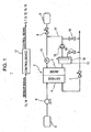
- Fig. 1 is a system diagram illustrating an embodiment of the structure of a fuel cell system including a drainage system for a fuel cell according to an embodiment of the present invention.
- a fuel cell system 1 includes a proton exchange membrane fuel cell stack 2 having an anode (fuel electrode) 3 and a cathode (oxidant electrode) 4.
- Air which functions as oxidant, is drawn into a compressor 6 through an air inlet 5 and is compressed.
- the compressed air is supplied to the cathode 4.
- Some of the supplied air is subjected to reaction at the cathode 4, and the remaining air is discharged out of the system after the pressure thereof is adjusted by an exhaust control valve 7.
- Hydrogen which functions as fuel gas, is stored in a fuel gas tank 8 at a high pressure.
- the high-pressure hydrogen in the fuel gas tank 8 is supplied to the anode 3 after the pressure thereof is controlled by a hydrogen regulating valve 9 and measured by a pressure gage 10.
- Unreacted fuel gas which is mixed with liquid water generated by the reaction, is discharged from the anode 3, is cycled through a fuel gas circuit 11, and is fed to the anode 3 again.
- a gas-liquid separator 20 is placed in the fuel gas circuit 11 to receive the fuel gas which is discharged from the anode 3 and has become mixed with the liquid water generated by the reaction, and the gas-liquid separator 20 separates the fuel gas from the liquid water.
- the fuel gas separated by the gas-liquid separator 20 is pressurized and conveyed by a fuel gas blower 12 in the fuel gas circuit 11, mixed with fresh hydrogen gas supplied from the hydrogen regulating valve 9, and is supplied to the anode 3.
- a purge valve 16 is disposed downstream of the fuel gas blower 12 in the fuel gas circuit. When impurities accumulate in the anode 3 or in the fuel gas circuit 11, the purge valve 16 is opened to discharge the impurities out of the system.
- the gas-liquid separator 20 is provided in a drainage system 13 to separate the fuel gas and the water from each other.
- the drainage system 13 includes a gas-liquid separator 20, a water tank 21, a water level sensor 14, and a drain valve 15.
- the drain valve 15 is controlled such that the water level is maintained between an upper limit and a lower limit while the fuel cell is in normal operation.
- a control device 17 controls the overall operation of the fuel cell system 1 and the water level in the water tank 21 by opening and closing the drain valve 15 on the basis of a water level signal obtained by the water level sensor 14.
- the control device 17 is a microprocessor including a CPU, a program ROM, a working RAM, and an input/output interface.
- the control device 17 is not particularly limited to this embodiment.
- Fig. 2A is a sectional view illustrating the gas-liquid separator 20 according to the first embodiment.
- Fig. 2B is a graph illustrating the relationship between the water level (vertical axis) and the output voltage of the water level sensor 14 (horizontal axis) according to the first embodiment.
- the drainage system 13 includes the gas-liquid separator 20 and the water tank 21 including a metal housing.
- the gas-liquid separation unit 20 receives anode exhaust, which is fluid including hydrogen and generated water, from the fuel cell stack 2.
- the gas-liquid separation unit 20 separates the liquid water and the gas component from each other.
- the liquid water is dropped into the water tank 21, and hydrogen gas mixed with water vapor is discharged from the gas-liquid separation unit 20.
- An upper portion 22 of the water tank 21 is structured as a large-diameter portion having a larger volume and a larger horizontal cross sectional area (second cross sectional area) than those of a lower portion 24.
- the lower portion 24 of the water tank 21 is structured as a small-diameter portion having a smaller volume and a smaller horizontal cross sectional area (first cross sectional area) than those of the upper portion.
- the upper portion 22 and the lower portion 24 may be connected to each other with a tapered portion 23 having a diameter that gradually decreases as it approaches the lower portion 24.
- the structure between the upper portion 22 and the lower portion 24 is not limited to this embodiment.
- the lower portion 24 has an outlet 25 through which the water is discharged from the water tank 21.
- the outlet 25 is connected to the drain valve 15 with a drainpipe 26.
- the water tank 21 has the water level sensor 14 for detecting the water level.
- the water level sensor 14 is a capacitance type water level sensor.
- the capacitance type water level sensor 14 outputs an analog signal representing the water level detected by the capacitance between the electrodes since the capacitance between the electrodes varies in accordance with the water level due to the difference between the dielectric constant of the air (about 1) and the dielectric constant of the liquid water (about 81).
- a positive electrode 27 is a metal body, which is fixed to and insulated from a lid 30 of the water tank 21 such that the positive electrode 27 extends downward from the lid 30 into the water tank 21.
- the positive electrode 27 functions as one of the electrodes of the water level sensor 14.
- the water level sensor 14 detects a voltage that is proportional to the capacitance between the positive electrode 27 at the center of the water tank 21 and an inner wall 40 of the water tank 21 made of metal.
- the inner wall 40 of the water tank 21 functions as the ground electrode (negative electrode), that is, the other electrode of the water level sensor 14.
- the water level is detected as shown in Fig. 2B .
- the control device 17 opens and closes the drain valve 15 so that the water level is positioned between the upper limit and the lower limit thereof shown in Fig. 2A . More specifically, the control device 17 opens the drain valve 15 when the water level in the water tank 21 detected by the water level sensor 14 is above the upper limit thereof, and closes the drain valve 15 when the water level is below the lower limit thereof. Accordingly, while the fuel cell system is in operation, the water level is maintained between the upper limit and the lower limit thereof, which are both provided in the upper portion 22 of the water tank 21.
- the control device 17 opens the drain valve 15 to drain the water from the water tank 21, and then closes the drain valve 15 when the water level reaches the stopped state water level.
- the stopped state water level is in the lower portion 24 of the water tank 21. Accordingly, when the operation of the fuel cell system is stopped, the water level is maintained at the lower portion 24, that is, at the small-diameter portion of the water tank having a small volume and a small cross sectional area. Thus, even if the outside temperature is below freezing and the liquid water in the water tank is frozen, the amount of ice to be melted is minimized. As a result, the time required for melting the ice can be minimized.
- the ice is positioned at the water level sensor unit 14. Therefore, an accurate water level can be detected and accurate water level control can be performed immediately when the ice is melted. As a result, the vehicle can be started quickly.
- the upper portion 22 of the water tank 21 has a larger volume and a larger cross sectional area than those of the lower portion 24. Therefore, while the fuel cell is in the operational state, even if the output level of the fuel cell 1 is high and a large amount of generated water suddenly flows into the water tank 21, the gas-liquid separation function can be maintained. In addition, when the fuel cell 1 is in the stopped state, the water is discharged until the water level reaches the lower portion 24 of the water tank 21 that has a small volume and a small cross sectional area. Thus, even when the water in the water tank 21 freezes, the amount of water that freezes in the water tank 21 is small. Therefore, the time required for melting the ice can be reduced and the draining process can be started quickly.
- the water tank 21 includes the upper portion 22, which is the large-diameter portion of the water tank 21 that has a large volume and a large cross sectional area, and the lower portion 24, which is the small-diameter portion of the water tank 21 that has a small volume and a small cross sectional area.
- the shape of the horizontal cross sectional area of the water tank 21 is not limited to circular, and effects similar to those of the present embodiment can, of course, also be obtained even when the cross sectional area is in another form such as elliptical or rectangular, as long as the volume and cross sectional area of the upper portion 22 of the water tank 21 are larger than those of the lower portion 24 of the water tank 21.
- FIG. 3 is a sectional view illustrating a drainage system 13 according to the second embodiment.
- the second embodiment differs from the first embodiment in that a separation wall 28 is disposed in the water tank 21, having a hole 29 that allows fluid communication with the water tank 21.
- the separation wall 28 serves as the ground electrode (negative electrode) of the water level sensor 14 in the upper portion 22 of the water tank 21.
- the positive electrode 27 functions as a common positive electrode for both of the ground electrodes (negative electrodes) served by the separation wall 28 in the upper portion 22 of the water tank 21 and the inner wall of the water tank 21 in the lower portion 24 of the water tank 21.
- Other structures of the second embodiment are similar to those of the first embodiment.
- the separation wall 28 is fixed to the lid 30 of the water tank 21 such that the separation wall 28 extends downward from the lid 30 into the water tank 21.
- the separation wall 28 divides the inner space of the water tank 21 into two sections, with one section contained inside the separation wall 28, and the other section located outside the separation wall 28.
- the bottom end of the separation wall 28 is at a height corresponding to the tapered portion 23 of the water tank 21.
- the bottom end of the separation wall 28 is open so that the sections inside and outside the separation wall 28 fluidly communicate with each other at the bottom end of the separation wall 28.
- the communication hole 29 is formed at a position above the upper limit of the water level in the separation wall 28 and allows the sections inside and outside the separation wall 28 to fluidly communicate with each other.
- the positive electrode 27 of the water level sensor 14 is disposed inside the separation wall 28. A bottom end portion of the positive electrode 27 extends to below the stopped state water level, which is at the lower portion 24 of the water tank 21.
- the separation wall 28 in the upper portion 22 of the water tank 21 and the inner wall of the water tank 21 in the lower portion 24 of the water tank 21 are used as the ground electrodes of the capacitance type water level sensor 14.
- the separation wall 28 is provided in the water tank 21, and the water level in the water tank 21 is detected on the basis of the capacitance between the separation wall 28 and the positive electrode 27 disposed at the center of the separation wall 28. Therefore, even when, for example, the vehicle in which the fuel cell system is mounted rocks or tilts and the water level suddenly becomes inclined in the water tank 21, movement of the water surface inside the separation wall 28 can be suppressed compared to the case in which no separation wall 28 is provided. Therefore, the water level at the center of the water tank 21 can be accurately detected.
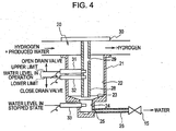
- Fig. 4 is a sectional view illustrating a drainage system 13 according to the third embodiment.
- the third embodiment differs from the first embodiment in that a separation wall 28 is disposed in the water tank 21.
- a hole 29 that allows fluid communication with the water tank 21 is additionally provided in the water tank 21.
- An upper limit level sensor 31, a lower limit level sensor 32, and a stopped state level sensor 33 are provided in place of the capacitance type water level sensor 14 that continuously detects the water level.
- Other structures of the third embodiment are similar to those of the first embodiment.
- the separation wall 28 is fixed to the lid 30 of the water tank 21 such that the separation wall 28 extends downward from the lid 30 into the water tank 21.
- the separation wall 28 divides the inner space of the water tank 21 into two sections, with one section contained inside the separation wall 28, and the other section located outside the separation wall 28.
- the bottom end of the separation wall 28 is at a height corresponding to the tapered portion 23 of the water tank 21.
- the bottom end of the separation wall 28 is open so that the sections inside and outside the separation wall 28 fluidly communicate with each other at the bottom end of the separation wall 28.
- the communication hole 29 is formed at a position above the upper limit of the water level in the separation wall 28 and allows the sections inside and outside the separation wall 28 to fluidly communicate with each other.
- the upper limit level sensor 31 and the lower limit level sensor 32 extend through the water tank 21 and the separation wall 28.
- the stoppage level sensor 33 is disposed at the height of the stopped state water level, which is set in the lower portion 24 of the water tank 21.
- the upper limit level sensor 31, the lower limit level sensor 32, and the stopped state level sensor 33 are, for example, optical level sensors. Each level sensor 31, 32, 33 outputs a binary signal representing whether the fluid that exists at the detection position is air or water.
- the level sensors 31, 32, 33 are also referred to as level switches.
- the control device 17 performs similar to that in the first embodiment except the drain valve 15 is controlled on the basis of three binary signals output from the upper limit level sensor 31, the lower limit level sensor 32, and the stoppage level sensor 33 in the present embodiment, whereas a continuous water level signal is used in the first embodiment.
- the water level within the separation wall 28 is detected by the level sensors in the upper portion 22 of the water tank 21. Therefore, even when, for example, the vehicle in which the fuel cell system is mounted rocks or tilts, the water level at the center of the water tank 21 can be accurately detected.
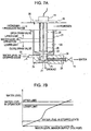
- Fig. 5A is a sectional view illustrating the drainage system 13 according to the fourth embodiment.
- Fig. 5B is a graph illustrating the relationship between the water level (vertical axis) and the output voltage of the water level sensor 14 (horizontal axis) according to the fourth embodiment.
- the fourth embodiment differs from the first embodiment in that a separation wall 28 is disposed in the water tank 21 having a hole 29 that allows fluid communication with the water tank 21.
- the separation wall 28 serves as the ground electrode (negative electrode) of the water level sensor 14 in the upper portion 22 of the water tank 21.
- the separation wall 28 is fixed to the lid 30 of the water tank 21 such that the separation wall 28 extends downward from the lid 30 into the water tank 21.
- the separation wall 28 divides the inner space of the water tank 21 into two sections, with one section contained inside the separation wall 28, and the other section located outside the separation wall 28.
- the bottom end of the separation wall 28 is at substantially the same height as the bottom end of the upper portion 22 of the water tank 21.
- the bottom end of the separation wall 28 is open so that the sections inside and outside the separation wall 28 fluidly communicate with each other at the bottom end of the separation wall 28.
- the communication hole 29 is formed at a position above the upper limit of the water level in the separation wall 28 and allows the sections inside and outside the separation wall 28 to fluidly communicate with each other.
- the positive electrode 27 of the water level sensor 14 is disposed inside the separation wall 28. A bottom end portion of the positive electrode 27 extends to below the stopped state water level, which is at the lower portion 24 of the water tank 21.
- the separation wall 28 in the upper portion 22 of the water tank 21, and the inner wall of the water tank 21 in the lower portion 24 of the water tank 21 are used as the ground electrodes of the capacitance type water level sensor 14.
- the dimensions are set such that the inner diameter of the separation wall 28 is equal to the inner diameter of the lower portion 24 of the water tank 21. Therefore, in the relationship between the voltage of the water level sensor 14 and the water level according to the present embodiment shown in Fig. 5B , the rate of change in the output voltage of the water level sensor 14 is high with respect to the unit change in the water level in the operational state and the stopped state. Therefore, the control device 17 can easily perform water-level control.
- Fig. 6A is a sectional view illustrating a drainage system 13 according to the fifth embodiment.
- Fig. 6B is a graph illustrating the relationship between the water level (vertical axis) and the output voltage of the water level sensor 14 (horizontal axis) according to the fifth embodiment.
- the fifth embodiment differs from the fourth embodiment in that a heater 34, such as a radiator, for heating the lower portion 24 of the water tank 21 and the drainpipe 26, is additionally provided.
- a heater 34 such as a radiator
- Other structures of the fifth embodiment are similar to those of the fourth embodiment.
- the heater 34 may also include portions for heating the lower portion 24 of the water tank 21 from the inside.
- the heater 34 is not limited to the radiator, and may also be a circulating heated medium in an area surrounding the lower portion 24 of the water tank 21.
- the control device 17 supplies electricity to the heater 34 when the water in the lower portion 24, that is, in the small-diameter portion of the water tank 21, is frozen. Thus, the ice in the smaller portion 24 and the drainpipe 26 can be melted.
- the heater 34 for heating the lower portion 24 of the water tank 21 since the heater 34 for heating the lower portion 24 of the water tank 21 is provided, the inner wall of the water tank 21, which functions as the ground electrode (negative electrode) of the water level sensor 14, can be directly heated. Thus, even when the water in the water tank 21 freezes while the fuel cell system 1 is in the stopped state, the time required for melting the ice can be minimized.
- Fig. 7A is a sectional view illustrating a drainage system 13 according to the sixth embodiment.
- Fig. 7B is a graph illustrating the relationship between the water level (vertical axis) and the output voltage of the water level sensor 14 (horizontal axis) according to the sixth embodiment.
- the sixth embodiment differs from the fifth embodiment in that a temperature sensor 35 is additionally provided on the inner wall of the lower portion of the water tank 21. A detection signal obtained from the temperature sensor 35 is input to the control device 17.
- Other structures of the sixth embodiment are similar to those of the fifth embodiment shown in Figs. 6A and 6B .
- the control device 17 accurately determines whether or not the water in the lower portion 24 of the water tank 21 is frozen by detecting the temperature of the inner wall of the lower portion 24 of the tank with the temperature sensor 35.
- the control device 17 decides whether to supply electricity to the heater 34 to start heating the water tank 21 and the drain tube 26 upon activation based on the determination of whether the water is frozen.
- the time at which the supply of electricity is to be stopped can be accurately determined based on the temperature detected by the temperature sensor 35.
- the determination it is determined that at least a portion of the water is frozen if the temperature is 2[deg.]C or less. In such a case, electricity is supplied to the heater 34. Then, if the temperature detected by the temperature sensor 35 is increased to, for example, 5[deg.]C, it is determined that the ice is melted. Thus, the supply of electricity to the heater 34 is stopped and the drain valve 15 can be opened. Then, the drain valve 15 is opened when the water level in the water tank 21 becomes higher than the upper limit thereof.
- the fuel cell system when the fuel cell system is activated, it can be accurately determined whether the water in the water tank 21 is frozen, that is, whether to supply electricity to the radiator that functions as the heater 34. Therefore, power consumption of the heater 34 can be minimized.
Landscapes
- Life Sciences & Earth Sciences (AREA)
- Engineering & Computer Science (AREA)
- Manufacturing & Machinery (AREA)
- Sustainable Development (AREA)
- Sustainable Energy (AREA)
- Chemical & Material Sciences (AREA)
- Chemical Kinetics & Catalysis (AREA)
- Electrochemistry (AREA)
- General Chemical & Material Sciences (AREA)
- Fuel Cell (AREA)
Claims (11)
- Système de drainage pour une pile à combustible (2), comprenant :un moyen formant séparateur (20) pour séparer un gaz combustible et une eau liquide d'un mélange gaz-liquide déchargé de la pile à combustible (2) ;un moyen de stockage (21) pour stocker l'eau liquide séparée par le séparateur gaz-liquide ;un moyen formant soupape de purge (15) en communication fluidique avec le moyen de stockage (21) pour décharger sélectivement l'eau liquide du moyen de stockage (21) ; etun moyen de commande (17) pour ouvrir et fermer sélectivement le moyen formant soupape de purge (15) ;dans lequel le moyen de stockage (21) comprend une partie inférieure (24) ayant une première aire de section transversale horizontale et une partie supérieure (22) ayant une deuxième aire de section transversale horizontale, la première aire de section transversale horizontale étant plus petite que la deuxième aire de section transversale horizontale ; etdans lequel le moyen de commande (17) est agencé pour ouvrir et fermer le moyen formant soupape de purge (15) pour maintenir un premier niveau d'eau à l'intérieur de la partie supérieure (22) du moyen de stockage (21) lorsque la pile à combustible (2) se trouve dans un état de fonctionnement etcaractérisé en ce que le moyen de commande (17) est agencé pour maintenir un deuxième niveau d'eau à l'intérieur de la partie inférieure (24) du moyen de stockage (21) lorsque la pile à combustible (2) se trouve dans un état d'arrêt,et le système comprenant en outre un capteur de niveau de limite supérieure (31), un capteur de niveau de limite inférieure (32) et un capteur de niveau d'état d'arrêt (33) pour détecter un niveau d'eau dans le moyen de stockage (21), où le moyen de commande (17) est agencé pour ouvrir et fermer le moyen formant soupape de purge (15) en réponse au niveau d'eau détecté,dans lequel les capteurs de niveau de limites supérieure et inférieure (31, 32) sont prévus dans la partie supérieure (22) du moyen de stockage (21), et le capteur de niveau d'état d'arrêt (33) est prévu dans la partie inférieure (24) du moyen de stockage (21) et est disposé à la hauteur du deuxième niveau d'eau.
- Système tel que revendiqué dans la revendication 1, dans lequel le moyen formant détecteur est disposé dans le moyen de stockage (21) et où le moyen de stockage (21) comprend une paroi de séparation (28) disposée dans le moyen de stockage (21), la paroi de séparation (28) étant agencée pour entourer au moins une partie (27, 31, 32, 33) du moyen formant détecteur (31, 32, 33).
- Système tel que revendiqué dans la revendication 2, dans lequel :le moyen formant détecteur comprend un capteur de niveau d'eau de type capacitif ayant une électrode de masse et une électrode positive (27) ;la paroi de séparation (28) constitue l'électrode de masse dans la partie supérieure (22) du moyen de stockage (21) et une paroi périphérique du moyen de stockage (21) constitue l'électrode de masse dans la partie inférieure (24) du moyen de stockage (21) ; et l'électrode positive est commune à la fois à la partie supérieure (22) et à la partie inférieure (24) du moyen de stockage (21).
- Système tel que revendiqué dans la revendication 3, dans lequel la paroi de séparation (28) a une troisième aire de section transversale horizontale qui est égale à la première aire de section transversale horizontale.
- Système tel que revendiqué dans l'une des revendications précédentes, dans lequel la partie inférieure (24) du moyen de stockage (21) définit un premier volume, la partie supérieure (22) du moyen de stockage (21) définit un deuxième volume qui est plus grand que le premier volume, et une partie conique (23) relie la partie supérieure (22) du moyen de stockage (21) à la partie inférieure (24) du moyen de stockage (21).
- Système tel que revendiqué dans l'une des revendications précédentes, comprenant un moyen formant élément chauffant (34) pour chauffer le moyen de stockage (21) par application de chaleur à la partie inférieure (24) du moyen de stockage (21).
- Système tel que revendiqué dans la revendication 6, comprenant un moyen formant détecteur de température situé à l'intérieur de la partie inférieure (24) du moyen de stockage (21), où le moyen de commande (17) est agencé pour activer et désactiver le moyen formant élément chauffant (34) sur la base d'une température détectée par le moyen formant détecteur de température (35).
- Système tel que revendiqué dans l'une des revendications précédentes, comprenant :un moyen formant capteur de niveau de seuil supérieur (31) et un moyen formant capteur de niveau de seuil inférieur (32) prévus dans la partie supérieure (22) du moyen de stockage (21) ;dans lequel le premier niveau d'eau à l'intérieur de la partie supérieure (22) du moyen de stockage (21) est maintenu entre le niveau de seuil supérieur et le niveau de seuil inférieur à l'état de fonctionnement.
- Procédé de commande de drainage d"eau liquide pour une pile à combustible (2), comprenant le fait :de séparer un gaz combustible et une eau liquide d'un mélange gaz-liquide déchargé de la pile à combustible (2) avec un séparateur gaz-liquide ;de recevoir l'eau liquide séparée par le séparateur gaz-liquide dans un réservoir d'eau (21), le réservoir d'eau (21) comportant une partie inférieure (24) ayant une première aire de section transversale horizontale et une partie supérieure (22) ayant une deuxième aire de section transversale horizontale, la première aire de section transversale horizontale étant plus petite que la deuxième aire de section transversale horizontale ; etd'ouvrir et de fermer sélectivement une soupape de purge (15) avec une unité de commande (17) pour maintenir un premier niveau d'eau à l'intérieur de la partie supérieure (22) du réservoir d'eau (21) lorsque la pile à combustible se trouve dans un état de fonctionnement etcaractérisé par le fait d'ouvrir et de fermer sélectivement la soupape de purge (15) avec l'unité de commande (17) pour maintenir un deuxième niveau d'eau à l'intérieur de la partie inférieure (24) du réservoir d'eau (21) lorsque la pile à combustible (2) se trouve dans un état d'arrêt,et le procédé comprenant en outre le fait d'ouvrir et de fermer la soupape de purge (15) avec l'unité de commande (17) en réponse à un niveau d'eau détecté par un capteur de niveau de limite supérieure (31), un capteur de niveau de limite inférieure (32) et un capteur de niveau d'état d'arrêt (33), où les capteurs de niveau de limites supérieure et inférieure (31, 32) sont prévus dans la partie supérieure (22) du réservoir d'eau (21), et le capteur de niveau d'état d'arrêt (33) est prévu dans la partie inférieure du réservoir d'eau (21) et est disposé à la hauteur du deuxième niveau d'eau.
- Procédé tel que revendiqué dans la revendication 9, comprenant le fait de chauffer le réservoir d'eau (21) avec un élément chauffant configuré pour appliquer de la chaleur à la partie inférieure (24) du réservoir d'eau (21).
- Véhicule ayant un système (1) tel que revendiqué dans l'une des revendications 1 à 8.
Applications Claiming Priority (1)
| Application Number | Priority Date | Filing Date | Title |
|---|---|---|---|
| JP2007258829A JP5446080B2 (ja) | 2007-10-02 | 2007-10-02 | 燃料電池の排水システム |
Publications (3)
| Publication Number | Publication Date |
|---|---|
| EP2045864A2 EP2045864A2 (fr) | 2009-04-08 |
| EP2045864A3 EP2045864A3 (fr) | 2009-09-30 |
| EP2045864B1 true EP2045864B1 (fr) | 2016-03-09 |
Family
ID=40266052
Family Applications (1)
| Application Number | Title | Priority Date | Filing Date |
|---|---|---|---|
| EP08165533.4A Ceased EP2045864B1 (fr) | 2007-10-02 | 2008-09-30 | Système de drainage pour pile à combustible |
Country Status (3)
| Country | Link |
|---|---|
| US (1) | US8877403B2 (fr) |
| EP (1) | EP2045864B1 (fr) |
| JP (1) | JP5446080B2 (fr) |
Cited By (2)
| Publication number | Priority date | Publication date | Assignee | Title |
|---|---|---|---|---|
| DE102024202193A1 (de) | 2024-03-08 | 2025-09-11 | Robert Bosch Gesellschaft mit beschränkter Haftung | Wasserabscheider für Brennstoffzelle und Verfahren zum Betreiben eines Wasserabscheiders |
| DE102024202186A1 (de) | 2024-03-08 | 2025-09-11 | Robert Bosch Gesellschaft mit beschränkter Haftung | Wasserabscheider für Brennstoffzelle und Verfahren zum Betreiben eines Wasserabscheiders |
Families Citing this family (22)
| Publication number | Priority date | Publication date | Assignee | Title |
|---|---|---|---|---|
| DE102008060533A1 (de) * | 2008-12-04 | 2010-06-10 | Daimler Ag | Flüssigkeitsabscheider für ein Brennstoffzellensystem |
| DE102009041938B4 (de) * | 2009-09-17 | 2013-10-31 | Seuffer Gmbh & Co.Kg | Heizungsanordnung |
| KR101688478B1 (ko) * | 2010-03-04 | 2016-12-21 | 삼성에스디아이 주식회사 | 리싸이클러와 이를 포함하는 연료전지의 물 관리 시스템과 이를 포함하는 연료전지 및 워터레벨 측정방법 |
| US9054354B2 (en) * | 2010-04-16 | 2015-06-09 | The Raymond Corporation | Fuel cell water disposal |
| US20130295476A1 (en) * | 2011-03-03 | 2013-11-07 | Panasonic Corporation | Gas-liquid separator and fuel cell system |
| JP6187433B2 (ja) | 2014-11-14 | 2017-08-30 | トヨタ自動車株式会社 | 気液分離器および燃料電池システム |
| DE102017110093A1 (de) * | 2016-05-18 | 2017-11-23 | Ford Global Technologies, Llc | Brennstoffzellen-spülkanalsystem |
| CN109863373B (zh) * | 2016-10-19 | 2021-12-07 | 三菱电机株式会社 | 制冷循环装置 |
| US11063277B2 (en) | 2017-05-24 | 2021-07-13 | Hyundai Motor Company | Method of controlling an ignition of a fuel cell vehicle |
| JP6933026B2 (ja) * | 2017-07-20 | 2021-09-08 | いすゞ自動車株式会社 | 尿素水残量表示装置 |
| CN108598528A (zh) * | 2018-04-11 | 2018-09-28 | 广东国鸿氢能科技有限公司 | 燃料电池阴极系统、吹扫系统、燃料电池的阴极吹扫方法 |
| JP7139754B2 (ja) * | 2018-07-26 | 2022-09-21 | トヨタ自動車株式会社 | 燃料電池システム |
| JP7087925B2 (ja) * | 2018-11-05 | 2022-06-21 | トヨタ自動車株式会社 | 燃料電池システム |
| JP2020077569A (ja) * | 2018-11-09 | 2020-05-21 | トヨタ自動車株式会社 | 燃料電池システム |
| KR102796855B1 (ko) * | 2019-03-18 | 2025-04-16 | 현대자동차주식회사 | 연료전지의 응축수 배출 제어시스템 및 제어방법 |
| JP7176503B2 (ja) | 2019-12-04 | 2022-11-22 | トヨタ自動車株式会社 | 燃料電池システム |
| CN112928310B (zh) * | 2019-12-05 | 2022-10-21 | 未势能源科技有限公司 | 气液分离器排水阀的控制方法和装置、燃料电池及交通工具 |
| WO2022002085A1 (fr) * | 2020-06-30 | 2022-01-06 | Ceres Intellectual Property Company Limited | Système de décongélation et procédé pour système de pile à combustible à oxyde solide |
| CN113972388A (zh) * | 2021-12-02 | 2022-01-25 | 北京亿华通科技股份有限公司 | 一种燃料电池排水系统及其控制方法及燃料电池系统 |
| JP2024038879A (ja) * | 2022-09-08 | 2024-03-21 | 愛三工業株式会社 | 燃料電池システム |
| CN115675188B (zh) * | 2022-10-28 | 2025-09-26 | 长城汽车股份有限公司 | 一种燃料电池汽车的排水方法、装置、设备、介质及车辆 |
| CN115832373B (zh) * | 2023-01-05 | 2026-03-20 | 长城汽车股份有限公司 | 一种车辆排水控制方法、装置、介质和车辆 |
Citations (1)
| Publication number | Priority date | Publication date | Assignee | Title |
|---|---|---|---|---|
| JP2004288486A (ja) * | 2003-03-24 | 2004-10-14 | Aisan Ind Co Ltd | 燃料電池システムの水抜き装置 |
Family Cites Families (15)
| Publication number | Priority date | Publication date | Assignee | Title |
|---|---|---|---|---|
| JPS6167522A (ja) | 1984-09-07 | 1986-04-07 | Nippon Denso Co Ltd | 小径厚板用ベンデイングロ−ル |
| JPS6167522U (fr) * | 1984-10-09 | 1986-05-09 | ||
| JPH0541234A (ja) * | 1991-06-28 | 1993-02-19 | Fuji Electric Co Ltd | 燃料電池冷却水系のレベルスイツチ |
| JPH0861715A (ja) * | 1994-08-17 | 1996-03-08 | Taikisha Ltd | 液・氷結物割合検出装置 |
| WO2000065676A1 (fr) * | 1999-04-23 | 2000-11-02 | Energy Partners, L.C. | Dispositif de pile a combustible supportant le gel et procede d'exploitation de ce systeme |
| US6489048B1 (en) * | 2000-02-11 | 2002-12-03 | Plug Power Inc. | Operating a fuel cell system during low power demand |
| JP5044881B2 (ja) * | 2003-05-14 | 2012-10-10 | トヨタ自動車株式会社 | 燃料電池システム |
| JP2005294197A (ja) * | 2004-04-05 | 2005-10-20 | Calsonic Kansei Corp | 液体タンク及び液温管理システム |
| EP1610119A1 (fr) * | 2004-06-24 | 2005-12-28 | Ngk Spark Plug Co., Ltd. | Capteur capacitif pour la détection de l'état d'un liquide |
| JP2006140044A (ja) * | 2004-11-12 | 2006-06-01 | Nissan Motor Co Ltd | 燃料電池システム |
| JP2007026892A (ja) * | 2005-07-15 | 2007-02-01 | Nissan Motor Co Ltd | 燃料電池システム |
| JP2007087718A (ja) * | 2005-09-21 | 2007-04-05 | Toyota Motor Corp | 気液分離器、および、この気液分離器を備える燃料電池システム |
| JP2007115485A (ja) * | 2005-10-19 | 2007-05-10 | Nissan Motor Co Ltd | 燃料電池システム |
| JP2007207556A (ja) * | 2006-02-01 | 2007-08-16 | Nissan Motor Co Ltd | 燃料電池システム及び燃料電池システムの排水制御方法 |
| JP4676365B2 (ja) | 2006-03-20 | 2011-04-27 | 新日本無線株式会社 | 利得切換増幅器 |
-
2007
- 2007-10-02 JP JP2007258829A patent/JP5446080B2/ja not_active Expired - Fee Related
-
2008
- 2008-09-30 EP EP08165533.4A patent/EP2045864B1/fr not_active Ceased
- 2008-10-01 US US12/243,251 patent/US8877403B2/en active Active
Patent Citations (1)
| Publication number | Priority date | Publication date | Assignee | Title |
|---|---|---|---|---|
| JP2004288486A (ja) * | 2003-03-24 | 2004-10-14 | Aisan Ind Co Ltd | 燃料電池システムの水抜き装置 |
Cited By (2)
| Publication number | Priority date | Publication date | Assignee | Title |
|---|---|---|---|---|
| DE102024202193A1 (de) | 2024-03-08 | 2025-09-11 | Robert Bosch Gesellschaft mit beschränkter Haftung | Wasserabscheider für Brennstoffzelle und Verfahren zum Betreiben eines Wasserabscheiders |
| DE102024202186A1 (de) | 2024-03-08 | 2025-09-11 | Robert Bosch Gesellschaft mit beschränkter Haftung | Wasserabscheider für Brennstoffzelle und Verfahren zum Betreiben eines Wasserabscheiders |
Also Published As
| Publication number | Publication date |
|---|---|
| JP5446080B2 (ja) | 2014-03-19 |
| EP2045864A2 (fr) | 2009-04-08 |
| US20090087699A1 (en) | 2009-04-02 |
| EP2045864A3 (fr) | 2009-09-30 |
| US8877403B2 (en) | 2014-11-04 |
| JP2009087858A (ja) | 2009-04-23 |
Similar Documents
| Publication | Publication Date | Title |
|---|---|---|
| EP2045864B1 (fr) | Système de drainage pour pile à combustible | |
| JP5256692B2 (ja) | 燃料電池システム | |
| KR100779890B1 (ko) | 연료 전지 시스템 및 연료 전지 시스템의 제어 방법 | |
| US6350536B1 (en) | Method for preventing compressor from freezing in automobile fuel cell system | |
| CN105720281B (zh) | 用于燃料电池系统的气体和冷凝水排放系统及其控制方法 | |
| US20160380282A1 (en) | Fuel cell system | |
| US7883812B2 (en) | Fuel cell system and transportation equipment including the same | |
| JP5338061B2 (ja) | 貯水タンク及び燃料電池システム | |
| KR20190000229A (ko) | 연료전지 차량의 응축수 배출장치 및 그 제어방법 | |
| JP4520898B2 (ja) | 燃料電池自動車および燃料電池自動車の水排出方法 | |
| EP4303428B1 (fr) | Véhicule à moteur à hydrogène avec système de stockage d'hydrogène liquide | |
| WO2008090430A1 (fr) | Appareil de drainage de l'eau de génération d'un système à pile à combustible | |
| JP5422979B2 (ja) | 燃料電池システム | |
| JP5199645B2 (ja) | 燃料電池システム | |
| JP2009193781A (ja) | 燃料電池システム | |
| US9991572B2 (en) | Arrangement and method for cooling a technical component including vaporizing water by residual thermal energy | |
| JP2010153246A (ja) | 燃料電池システム | |
| JP7299829B2 (ja) | 燃料電池システム | |
| US11239478B2 (en) | Fuel cell system and purge method therefor | |
| JP6222191B2 (ja) | 燃料電池システム | |
| JP2006140044A (ja) | 燃料電池システム | |
| WO2009024204A2 (fr) | Procédé et appareil pour déterminer un point de commutation pour régulation de niveau de remplissage | |
| JP2013206774A (ja) | 燃料電池システム | |
| US20080160368A1 (en) | Fuel cell system | |
| JP2006313664A (ja) | 燃料電池車両 |
Legal Events
| Date | Code | Title | Description |
|---|---|---|---|
| PUAI | Public reference made under article 153(3) epc to a published international application that has entered the european phase |
Free format text: ORIGINAL CODE: 0009012 |
|
| AK | Designated contracting states |
Kind code of ref document: A2 Designated state(s): AT BE BG CH CY CZ DE DK EE ES FI FR GB GR HR HU IE IS IT LI LT LU LV MC MT NL NO PL PT RO SE SI SK TR |
|
| AX | Request for extension of the european patent |
Extension state: AL BA MK RS |
|
| PUAL | Search report despatched |
Free format text: ORIGINAL CODE: 0009013 |
|
| AK | Designated contracting states |
Kind code of ref document: A3 Designated state(s): AT BE BG CH CY CZ DE DK EE ES FI FR GB GR HR HU IE IS IT LI LT LU LV MC MT NL NO PL PT RO SE SI SK TR |
|
| AX | Request for extension of the european patent |
Extension state: AL BA MK RS |
|
| 17P | Request for examination filed |
Effective date: 20091027 |
|
| 17Q | First examination report despatched |
Effective date: 20091201 |
|
| AKX | Designation fees paid |
Designated state(s): DE FR GB |
|
| GRAP | Despatch of communication of intention to grant a patent |
Free format text: ORIGINAL CODE: EPIDOSNIGR1 |
|
| INTG | Intention to grant announced |
Effective date: 20150831 |
|
| GRAS | Grant fee paid |
Free format text: ORIGINAL CODE: EPIDOSNIGR3 |
|
| GRAA | (expected) grant |
Free format text: ORIGINAL CODE: 0009210 |
|
| AK | Designated contracting states |
Kind code of ref document: B1 Designated state(s): DE FR GB |
|
| REG | Reference to a national code |
Ref country code: GB Ref legal event code: FG4D |
|
| REG | Reference to a national code |
Ref country code: DE Ref legal event code: R096 Ref document number: 602008042656 Country of ref document: DE |
|
| REG | Reference to a national code |
Ref country code: FR Ref legal event code: PLFP Year of fee payment: 9 |
|
| REG | Reference to a national code |
Ref country code: DE Ref legal event code: R097 Ref document number: 602008042656 Country of ref document: DE |
|
| PLBE | No opposition filed within time limit |
Free format text: ORIGINAL CODE: 0009261 |
|
| STAA | Information on the status of an ep patent application or granted ep patent |
Free format text: STATUS: NO OPPOSITION FILED WITHIN TIME LIMIT |
|
| 26N | No opposition filed |
Effective date: 20161212 |
|
| REG | Reference to a national code |
Ref country code: FR Ref legal event code: PLFP Year of fee payment: 10 |
|
| REG | Reference to a national code |
Ref country code: FR Ref legal event code: PLFP Year of fee payment: 11 |
|
| PGFP | Annual fee paid to national office [announced via postgrant information from national office to epo] |
Ref country code: FR Payment date: 20210812 Year of fee payment: 14 |
|
| PGFP | Annual fee paid to national office [announced via postgrant information from national office to epo] |
Ref country code: DE Payment date: 20210818 Year of fee payment: 14 Ref country code: GB Payment date: 20210825 Year of fee payment: 14 |
|
| REG | Reference to a national code |
Ref country code: DE Ref legal event code: R119 Ref document number: 602008042656 Country of ref document: DE |
|
| GBPC | Gb: european patent ceased through non-payment of renewal fee |
Effective date: 20220930 |
|
| PG25 | Lapsed in a contracting state [announced via postgrant information from national office to epo] |
Ref country code: FR Free format text: LAPSE BECAUSE OF NON-PAYMENT OF DUE FEES Effective date: 20220930 Ref country code: DE Free format text: LAPSE BECAUSE OF NON-PAYMENT OF DUE FEES Effective date: 20230401 |
|
| PG25 | Lapsed in a contracting state [announced via postgrant information from national office to epo] |
Ref country code: GB Free format text: LAPSE BECAUSE OF NON-PAYMENT OF DUE FEES Effective date: 20220930 |