EP2045883A1 - Abschirmstruktur, verbinderbaugruppe und verbinderstruktur mit abschirmstruktur, gehäusebaugruppe und elektrischer kompressor - Google Patents
Abschirmstruktur, verbinderbaugruppe und verbinderstruktur mit abschirmstruktur, gehäusebaugruppe und elektrischer kompressor Download PDFInfo
- Publication number
- EP2045883A1 EP2045883A1 EP07767221A EP07767221A EP2045883A1 EP 2045883 A1 EP2045883 A1 EP 2045883A1 EP 07767221 A EP07767221 A EP 07767221A EP 07767221 A EP07767221 A EP 07767221A EP 2045883 A1 EP2045883 A1 EP 2045883A1
- Authority
- EP
- European Patent Office
- Prior art keywords
- structural body
- shield
- casing
- tube section
- connector
- Prior art date
- Legal status (The legal status is an assumption and is not a legal conclusion. Google has not performed a legal analysis and makes no representation as to the accuracy of the status listed.)
- Withdrawn
Links
- 210000000078 claw Anatomy 0.000 claims abstract description 49
- 239000004020 conductor Substances 0.000 claims abstract description 14
- 238000003780 insertion Methods 0.000 claims description 32
- 230000037431 insertion Effects 0.000 claims description 32
- 238000003825 pressing Methods 0.000 claims description 7
- 238000003466 welding Methods 0.000 claims description 4
- 238000007789 sealing Methods 0.000 claims description 3
- 239000011347 resin Substances 0.000 description 10
- 229920005989 resin Polymers 0.000 description 10
- 239000000463 material Substances 0.000 description 7
- 239000002184 metal Substances 0.000 description 7
- 238000000034 method Methods 0.000 description 6
- 238000004378 air conditioning Methods 0.000 description 4
- 230000000694 effects Effects 0.000 description 4
- 101000793686 Homo sapiens Azurocidin Proteins 0.000 description 3
- 230000000712 assembly Effects 0.000 description 2
- 238000000429 assembly Methods 0.000 description 2
- 238000010586 diagram Methods 0.000 description 2
- 238000004519 manufacturing process Methods 0.000 description 2
- 229920001707 polybutylene terephthalate Polymers 0.000 description 2
- 229910001369 Brass Inorganic materials 0.000 description 1
- 239000010951 brass Substances 0.000 description 1
- 238000001816 cooling Methods 0.000 description 1
- 230000006866 deterioration Effects 0.000 description 1
- 230000007774 longterm Effects 0.000 description 1
- 230000002093 peripheral effect Effects 0.000 description 1
- 239000005011 phenolic resin Substances 0.000 description 1
- -1 polybutylene terephthalate Polymers 0.000 description 1
- 239000003507 refrigerant Substances 0.000 description 1
- 238000005057 refrigeration Methods 0.000 description 1
- 239000000057 synthetic resin Substances 0.000 description 1
- 229920003002 synthetic resin Polymers 0.000 description 1
Images



Classifications
-
- F—MECHANICAL ENGINEERING; LIGHTING; HEATING; WEAPONS; BLASTING
- F04—POSITIVE - DISPLACEMENT MACHINES FOR LIQUIDS; PUMPS FOR LIQUIDS OR ELASTIC FLUIDS
- F04B—POSITIVE-DISPLACEMENT MACHINES FOR LIQUIDS; PUMPS
- F04B39/00—Component parts, details, or accessories, of pumps or pumping systems specially adapted for elastic fluids, not otherwise provided for in, or of interest apart from, groups F04B25/00 - F04B37/00
- F04B39/12—Casings; Cylinders; Cylinder heads; Fluid connections
-
- H—ELECTRICITY
- H01—ELECTRIC ELEMENTS
- H01R—ELECTRICALLY-CONDUCTIVE CONNECTIONS; STRUCTURAL ASSOCIATIONS OF A PLURALITY OF MUTUALLY-INSULATED ELECTRICAL CONNECTING ELEMENTS; COUPLING DEVICES; CURRENT COLLECTORS
- H01R13/00—Details of coupling devices of the kinds covered by groups H01R12/70 or H01R24/00 - H01R33/00
- H01R13/648—Protective earth or shield arrangements on coupling devices, e.g. anti-static shielding
-
- H—ELECTRICITY
- H01—ELECTRIC ELEMENTS
- H01R—ELECTRICALLY-CONDUCTIVE CONNECTIONS; STRUCTURAL ASSOCIATIONS OF A PLURALITY OF MUTUALLY-INSULATED ELECTRICAL CONNECTING ELEMENTS; COUPLING DEVICES; CURRENT COLLECTORS
- H01R13/00—Details of coupling devices of the kinds covered by groups H01R12/70 or H01R24/00 - H01R33/00
- H01R13/46—Bases; Cases
- H01R13/52—Dustproof, splashproof, drip-proof, waterproof, or flameproof cases
- H01R13/5205—Sealing means between cable and housing, e.g. grommet
Definitions
- the present invention relates to a connector related structure which is used for vehicles, etc., and specifically, to a shield structural body for a connector, a connector assembly and a connector structural body having the shield structural body, a casing assembly using the connector assembly, and an electric compressor provided with the casing assembly, which are suitable for an electric compressor in an air conditioning system for vehicles, etc.
- Patent document 1 discloses an assembling-type shield connector comprising a tubular outer housing made of an insulating resin, a tubular metal shell which is inserted into the outer housing and fixed therein by engaging means, an inner housing made of an insulating resin which is inserted into the metal shell to be fixed by engaging means, a shield cable connected with a terminal which is contained in the inner housing, a rear shell which is fitted to be engaged with a rear section of the metal shell by engaging means to seal the rear opening of the metal shell, an annular cap made of an insulating resin which nips a contact section with a shield section of the shield cable inserted into the semi-annular opposing contact sections elongated at the rear sections of the metal shell and the rear shell, a rear cover made of a synthetic resin which is fitted into and engaged with a rear end section of the outer housing by engaging means and which delivers out the shield cable.
- Patent document 2 discloses an inverter integrated electric compressor for vehicles comprising a compressor section being a part of a refrigerating cycle device , a motor section which is connected integrally with the compressor section to drive the compressor section, a housing which contains the compressor section and the motor section, and an inverter circuit section which has predetermined number of electric power switching elements and transforms a direct current power to a three-phase alternating current power to supply the electric power to the motor section, and the compressor performing cooling by using low-pressure refrigerant gas, characterized in that each electric power switching element is composed separately of a discrete transistor having a side surface on which an electrode terminal is projected and a bottom surface which is contacted directly to an outer circumferential surface of a peripheral wall of a part of the housing surrounding the motor section.
- the electric connection between the shield structural body and the shield cable braid is performed by pushing contact where a pushing force is obtained by engagement by pushing the end cap onto the outer housing.
- the end cap and the outer housing are formed of insulating resin materials and such resin materials are inevitable to deteriorate by long-term use or temperature environment. Further, it is likely to use vehicles for more than 5 to 10 years and especially the environment in an engine room is very severe for resin materials because of exhausted heat from the engine and vibration. Furthermore, because an electric compressor used in a refrigeration cycle of an air conditioning system for vehicles is installed closely to an engine, the environment around it is further severer.
- an object of the present invention is to provide a shield structural body which can be manufactured at a low cost, a connector assembly which has a high productivity and can be manufactured at a low cost, a connector structural body which has a high reliability, a casing assembly using them which has a high versatility, and an electric compressor having these and being easy to cope with change in models.
- a shield structural body is a shield structural body, which is formed of an electrically conductive material, and which has a tube section, a ground electrode terminal formed electrically integrally with the tube section, a plurality of claw sections which are formed integrally with the tube section and projected at least either radially outward or inward from the tube section, and engageable with a shield structural body holding member.
- the cost can be reduced by decrease of the number of parts.
- This shield structural body may be formed after parts corresponding to the tube section, the ground electrode terminal and the claw sections are punched out integrally by pressing. By such a structure, the shield structural body can be manufactured more easily, and the cost can be reduced by more decrease of the number of parts.
- the ground electrode terminal may be formed integrally by caulking or welding.
- the present invention also provides a connector assembly A comprising a shield structural body as described above.
- a connector assembly A having a shield structural body is a connector assembly A having a shield structural body, comprising:
- a connector assembly A having a shield structural body is a connector assembly A having a shield structural body comprising:
- a connector assembly A having a shield structural body is a connector assembly A having a shield structural body, comprising:
- the present invention also provides a connector structural body comprising:
- the present invention also provides a casing assembly comprising a connector assembly A (the above-described embodiment 1) as described above, a casing which has an opening hole and provided with a control circuit therein and a main electrode of which one end is connected to the control circuit and the other end is delivered out from the opening hole, wherein the main electrode is inserted into an insertion hole provided in the inner housing to be engaged with it, and the casing and the flange portion of the outer hosing are fixed to each other.
- a casing assembly because the functions (shielding, connecting and engaging) required as a shield structural body are given integrally, the cost can be reduced by decrease of the number of parts.
- the claw sections are engaged with at least either the outer housing-side surface of the deep groove portion or the inner housing-side surface of the deep groove portion as well as an insertion of the shield structural body into the deep groove portion, another engaging means is not required, and the inserting operation and the engaging operation can be merged in assembling, therefore the assembly efficiency can be improved.
- the flange portion of the outer housing is fixed to the opening hole portion provided on the side surface of the casing, the mounting location and the mounting direction of the connector assembly depend only on the casing. Therefore, if the hole portion location of the casing is selected in accordance with the mounting location and the mounting direction of the connector assembly which vary depending on vehicles, the casing assembly where the other parts are unaffected in assembling can be realized.
- the present invention also provides a casing assembly comprising a connector assembly A (the above-described embodiment 2), a casing which has an opening hole and provided with a control circuit therein and a main electrode of which one end is connected to the control circuit and the other end is delivered out from the opening hole, wherein the main electrode is inserted into an insertion hole provided in the inner housing to be engaged with it, and the casing and the flange portion of the outer housing are fixed to each other while the claw sections of the shield structural body are nipped by a casing as an outer housing fixing structural body and an end surface of the flange portion of the outer housing.
- the mounting location and the mounting direction of the connector assembly depend only on the casing. Therefore, if the hole portion location of the casing is selected in accordance with the mounting location and the mounting direction of the connector assembly which vary depending on vehicles, the casing assembly where the other parts are unaffected in assembling can be realized.
- the present invention also provides a casing assembly comprising a connector assembly A (The above-described embodiment 3), a casing which has an opening hole and provided with a control circuit therein and a main electrode of which one end is connected to the control circuit and the other end is delivered out from the opening hole, wherein the main electrode is inserted into an insertion hole provided in the inner housing to be engaged with it, and the casing and the flange portion of the outer hosing are fixed to each other while the claw sections of the shield structural body are pushed into a tapered inner circumferential surface of the opening hole portion to be engaged with the inner circumferential surface.
- the tube section of the shield structural body is larger than the opening hole of the casing. Because when the tube section of the shield structural body is larger than the opening section of the casing, the shield structural body is to be surrounded by the deep groove portion and the side surface of the casing, therefore even if the engagement of the shield structural body is broken by a damage of the claw section, the shield structural body cannot be disengaged from the connector assembly to be fallen out. Thus, a casing assembly with a high reliability can be realized.
- the casing is formed of an electrically conductive material and at least either the tube section of the shield structural body or the claw section comes into contact with the casing. If the casing is made of an electrically conductive material and at least either the tube section of the shield structural body or the claw section comes into contact with the casing, because the casing is to be connected electrically to the shield structural body, additional grounding means are not to be required and the assembly efficiency thereof can be improved.
- the present invention also provides an electric compressor comprising a closed container body, an electric element and compressing element provided inside the closed container body, and a casing assembly as described above provided outside the closed container body, the casing assembly having therein a control circuit for controlling the electric element.
- a high voltage connector assembly as a power source for operating the electric element and a low voltage connector assembly as a power source for operating the control circuit are provided in an identical side surface of the casing assembly.
- a space required for the interconnection of the electrical compressor mounted in an engine room can be restricted in a single direction of the mounting direction of the connector assembly, the space required for mounting can be narrowed, and the mounting efficiency can be improved.
- the functions (shielding, connecting and engaging) required as a shield structural body are given integrally, the cost can be reduced by decrease of the number of parts.
- the inserting operation and the engaging operation of the shield structural body can be merged in assembling, and the assembly efficiency can be improved.
- the shield structural body can be provided only in the male side connector (only in the connector assembly A), so that the cost can be reduced by decrease of the number of parts, and the connectors can be strongly connected electrically and mechanically each other to realize a connector structure with a high reliability.
- the assembly efficiency can be improved. Furthermore, because the flange portion of the outer housing is fixed to the opening hole portion provided on the side surface of the casing, the mounting location and the mounting direction of the connector assembly depend only on the casing, so that if the hole location of the casing is selected in accordance with the mounting location and the mounting direction of the connector assembly which vary depending on vehicles, the casing assembly where the other parts are unaffected in assembling can be realized.
- the electric compressor according to the present invention it can be realized that effects in the shield structural body, the connector assembly, the connector structural body and the casing assembly as described above are produced in combination, therefore the assembly efficiency and productivity of the electric compressor can be improved and the cost thereof can be reduced.
- Fig.1 shows a connector structural body according to the present invention.
- the connector structural body contains a shield structural body according to the present invention and a connector assembly A according to the present invention.
- 1 means a whole connector structural body
- connector structural body 1 comprises male connector 2 as a connector assembly A according to an embodiment of the present invention and female connector 3 assembly B as a connector assembly B in the present invention which is fitted with male connector 2.
- Male connector 2 and female connector 3 are, for example, made of such resins as PBT (polybutylene terephthalate), etc.
- Male connector 2 comprises outer housing 4, inner housing 5 and flange portion 6 formed integrally with outer housing 4.
- main electrode 10 is provided in insertion hole 9.
- the structure of main electrode 10 is not only a terminal structure as depicted in the figure but any structure with a connecting element.
- shield structural body 14 made of an electrically conductive material which comprises tube section 11, ground electrode terminal 12 formed electrically integrally with the tube section, a plurality of claw sections 13 which are formed integrally with tube section 11 and projected at least either radially outward or inward (radially outward in the depicted example), and engageable with a shield structural body holding member (such as outer housing 4 and/or inner housing 5 of male connector 2, or an end surface of outer housing 4 and a casing as described later, or a inner circumferential surface of an opening hole formed in a casing as described later).
- a shield structural body holding member such as outer housing 4 and/or inner housing 5 of male connector 2, or an end surface of outer housing 4 and a casing as described later, or a inner circumferential surface of an opening hole formed in a casing as described later.
- Ground electrode terminal 12 is inserted into insertion hole 8, and claw sections 13 are engaged with at least either an outer housing-side surface of a deep groove portion or an inner housing-side surface of a deep groove portion (with an outer housing-side surface of a deep groove portion).
- Shield structural body 14, especially tube section thereof, is made of an electrically conductive material, such as a nickel-plated or tinned brass.
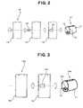
- ground electrode terminal 12 and claw sections 13 may be punched out integrally by pressing to plate-like material, ground electrode terminal 12 may be formed in a predetermined connectable shape, and ground electrode terminal 12 may be bended toward a predetermined direction and then, parts corresponding to the tube section may be rounded to form tube section 11, so that tube section 11, ground electrode terminal 12 and claw sections 13 can be integrated to form shield structural body 14.
- ground electrode terminal 12a may be formed integrally by caulking or welding (by welding in the depicted example) so that tube section 11, ground electrode terminal 12a and claw sections 13 can be integrated to form shield structural body 14.
- shield structural body 14, 14a because tube section 11, ground electrode terminal 12, 12a, and claw sections 13 are integrated, the functions (shielding, connecting and engaging) as a shield structural body are given integrally, therefore the cost can be reduced by decrease of the number of parts.
- male connector 2 as a connector assembly A comprising such a shield structural body 14, 14a
- claw sections 13 are engaged with at least either the outer housing-side surface of the deep groove portion or the inner housing-side surface of the deep groove portion, as well as an insertion of shield structural body 14, 14a into deep groove portion 7, another engaging means is not required, and the inserting operation and the engaging operation can be merged in assembling, therefore the assembly efficiency can be improved.
- the engaging or holding structure of the shield structural body may be the structure where it is engaged in deep groove portion 7 as described above, or the structure as depicted in Fig. 4 for example, where claw sections 13a of shield structural body 14b are nipped by structural body 21 (for example, a casing described later, especially a metal casing) fixing outer housing 4 and an end surface of flange portion 6 of outer housing 4. Also in such a case, another engaging means is not required, and the operation fixing shield structural body 14b and the operation fixing outer housing 4 with structural body 21 can be merged in assembling, therefore the assembly efficiency can be improved.
- the engaging or holding structure of the shield structural body may be the structure as depicted in Fig. 5 for example, where claw sections 13b of shield structural body 14c are pushed into tapered inner circumferential surface 23 of hole 22 formed in structural body 21 (for example, a casing described later, especially a metal casing) fixing outer housing 4 and are engaged with inner circumferential surface 23 of the hole. Also in such a case, another engaging means is not required, and the operation fixing shield structural body 14c and the operation fixing outer housing 4 with structural body 21 can be merged in assembling, therefore the assembly efficiency can be improved.
- claw sections 13b are pushed concentrically along an tapered surface of tapered inner circumferential surface 23 of hole 22 and deformed inward to be engaged, claw sections 13b are strongly held, and shield structural body 14c is surely grounded to the side of structural body 21.
- connector structural body 1 comprises male connector 2 as a connector assembly A having a shield structure as above-described and female connector 3 as a connector assembly B which is fitted and connected mechanically and electrically with male connector 2.
- Shield cable 31 (2-pin) is introduced at the side of female connector 3, and at an end section of shield cable 31 are female terminal 32 for connecting to a main electrode and male terminal 33 for connecting a ground electrode terminal which is provided at an end section of shield cable 31 and fixed to a shield braid by caulking.
- main housing 34 of female connector 3 are provided insertion hole 35 for inserting female terminal 32 and insertion hole 36 for inserting male terminal 33.
- end cap 37 sealing an opening end section of the housing and delivering out shield cable 31, cable seal 38 made of rubber, etc. which is nipped by main housing 34 and end cap 37 and seals watertightly an inner circumferential surface of end cap 37 and a periphery of shield cable 31 while delivering out shield cable 31 and housing seal 39 made of rubber, etc. which is contained in main housing 34 and seals watertightly inner housing 5 of the side of male connector 2 as a connector assembly A and main housing 34.
- the connecting structure between female connector 32 and male connector 33 (ground terminal) at an end section of shield cable 31 may be the structure as depicted in Fig. 6 for example, where an end section for pulling out the terminal of shield cable 31 is solidified by resin.
- the structure of providing shield structural body 14 only to male connector 2 (only to the connector assembly A) can decrease the number of parts, and therefore, the cost can be reduced. Further, because the braid of shield cable 31 and shield structural body 14 are connected by linking ground electrode terminal 33 fixed by caulking to the braid of shield cable 31 and ground electrode terminal 12 formed integrally with shield structural body 14, they can be strongly connected electrically and mechanically, therefore a connector structure with a high reliability can be realized.
- a connector assembly A in connector structural body 1 as described above may be incorporated in a casing assembly.
- a casing in the casing assembly is regarded as a structural body which fixes an outer housing of a connector assembly A
- any connector assembly A of the above-described embodiments 1,2,3 can be accepted.
- a connector assembly A may be mounted with casing 42 of electric compressor 41 to form casing assembly 43 for electric compressor 41.
- casing 42 is made of a electrically conductive material, and at least either tube section 11 or claw sections 13 of shield structural body 14 are come into contact with casing 42.
- Electric compressor 41 comprises closed container body 44, electric element and compressing element (not shown) provided inside closed container body 44 and casing assembly 43 provided outside closed container body 44, casing assembly having therein a control circuit (not shown) for controlling the electric element.
- high voltage connector assembly 45 formed by connector assembly A as a power source for operating the electric element
- low voltage connector assembly 46 formed by connector assembly A as a power source for operating the control circuit. If connector assemblies 45,46 with the targeted shield structure are mounted and provided in an identical side surface of casing assembly 34, because a space required for the interconnection of electric compressor 41 mounted in an engine room, etc. can be restricted in a single direction of the mounting direction of connector assemblies 45,46 the space required for mounting can be narrowed, and the mounting efficiency can be improved.
- the connector-related structure according the present invention can be usually applied to a connector for general devices, and specifically, it is suitable for an electric compressor for an air conditioning system for vehicles, etc.
Landscapes
- Engineering & Computer Science (AREA)
- Mechanical Engineering (AREA)
- General Engineering & Computer Science (AREA)
- Details Of Connecting Devices For Male And Female Coupling (AREA)
- Connector Housings Or Holding Contact Members (AREA)
Applications Claiming Priority (2)
| Application Number | Priority Date | Filing Date | Title |
|---|---|---|---|
| JP2006187627A JP4562699B2 (ja) | 2006-07-07 | 2006-07-07 | 電動圧縮機 |
| PCT/JP2007/062382 WO2008004442A1 (en) | 2006-07-07 | 2007-06-20 | Shield structure, connector assembly and connector structure having shield structure, casing assembly, and electric compressor |
Publications (2)
| Publication Number | Publication Date |
|---|---|
| EP2045883A1 true EP2045883A1 (de) | 2009-04-08 |
| EP2045883A4 EP2045883A4 (de) | 2012-10-10 |
Family
ID=38894413
Family Applications (1)
| Application Number | Title | Priority Date | Filing Date |
|---|---|---|---|
| EP07767221A Withdrawn EP2045883A4 (de) | 2006-07-07 | 2007-06-20 | Abschirmstruktur, verbinderbaugruppe und verbinderstruktur mit abschirmstruktur, gehäusebaugruppe und elektrischer kompressor |
Country Status (5)
| Country | Link |
|---|---|
| US (1) | US8083545B2 (de) |
| EP (1) | EP2045883A4 (de) |
| JP (1) | JP4562699B2 (de) |
| CN (1) | CN101485052B (de) |
| WO (1) | WO2008004442A1 (de) |
Families Citing this family (11)
| Publication number | Priority date | Publication date | Assignee | Title |
|---|---|---|---|---|
| US8070014B2 (en) | 2007-08-24 | 2011-12-06 | Seaquist Closures L.L.C. | Liner piercing twist closure |
| JP4911628B2 (ja) | 2008-01-28 | 2012-04-04 | 株式会社リコー | 画像処理方法、画像処理装置及び画像撮像装置 |
| EP2666673B1 (de) * | 2010-12-27 | 2015-03-04 | Yazaki Corporation | Kabelbaum-Abschirmungsstruktur |
| JP5917013B2 (ja) * | 2011-04-19 | 2016-05-11 | 住友電装株式会社 | シールドコネクタ |
| US8388378B2 (en) * | 2011-06-28 | 2013-03-05 | Tyco Electronics Corporation | Electrical connector |
| US8328566B1 (en) * | 2011-07-08 | 2012-12-11 | Danfoss Scroll Technologies, Llc | Terminal connection for sealed compressor |
| US8597033B2 (en) * | 2012-02-10 | 2013-12-03 | Cheng Uei Precision Industry Co., Ltd. | Receptacle connector |
| JP6727951B2 (ja) * | 2016-06-24 | 2020-07-22 | 三菱重工サーマルシステムズ株式会社 | 電動圧縮機の電線導入部構造、これを備えたシールド電線、および電動圧縮機 |
| US9876323B1 (en) * | 2016-12-12 | 2018-01-23 | Avx Corporation | Hermaphroditic pin and socket connector |
| JP7023499B2 (ja) * | 2018-02-14 | 2022-02-22 | 日本圧着端子製造株式会社 | 電気コネクタ |
| KR20240054492A (ko) * | 2022-10-19 | 2024-04-26 | 한온시스템 주식회사 | 전동 압축기 |
Family Cites Families (19)
| Publication number | Priority date | Publication date | Assignee | Title |
|---|---|---|---|---|
| JPH0525188Y2 (de) * | 1987-05-27 | 1993-06-25 | ||
| JP2509408Y2 (ja) * | 1990-08-31 | 1996-09-04 | 第一電子工業株式会社 | 電気コネクタ |
| JPH0523459U (ja) * | 1991-09-05 | 1993-03-26 | ヒロセ電機株式会社 | 電気コネクタ構造 |
| JP2598584Y2 (ja) * | 1991-09-12 | 1999-08-16 | 矢崎総業株式会社 | 組立式シールドコネクタ |
| JPH0587850U (ja) * | 1992-04-30 | 1993-11-26 | 多治見無線電機株式会社 | 多芯ケーブル用コネクタ |
| NL9400321A (nl) * | 1994-03-03 | 1995-10-02 | Framatome Connectors Belgium | Connector voor een kabel voor hoogfrequente signalen. |
| JP3433433B2 (ja) * | 1994-03-07 | 2003-08-04 | 矢崎総業株式会社 | シールドコネクタ |
| JP3279833B2 (ja) * | 1994-09-07 | 2002-04-30 | 矢崎総業株式会社 | 機器直付用シールドコネクタ |
| JP3065907B2 (ja) * | 1995-03-30 | 2000-07-17 | 住友電装株式会社 | アンチロックブレーキシステムにおける油圧ユニット一体型電子制御ユニット |
| JP3388104B2 (ja) * | 1996-08-28 | 2003-03-17 | 住友電装株式会社 | シールドコネクタ |
| JPH10312856A (ja) * | 1997-05-15 | 1998-11-24 | Yazaki Corp | 機器直付用シールドコネクタ |
| US6010348A (en) * | 1997-05-20 | 2000-01-04 | Alden Products Company | Field-assembled two-piece snap-fit self-sealed electrical connector |
| JP3347662B2 (ja) * | 1998-02-04 | 2002-11-20 | ヒロセ電機株式会社 | 電気コネクタ |
| JP3802742B2 (ja) * | 2000-10-06 | 2006-07-26 | 矢崎総業株式会社 | シールドコネクタ |
| JP3544522B2 (ja) * | 2000-11-28 | 2004-07-21 | 日本圧着端子製造株式会社 | モジュラジャック及びその取付構造 |
| JP4550305B2 (ja) * | 2001-03-21 | 2010-09-22 | 古河電気工業株式会社 | 機器接続用シールドコネクタ |
| JP2002313453A (ja) * | 2001-04-18 | 2002-10-25 | Yazaki Corp | 機器直付け用シールドコネクタ |
| JP4045125B2 (ja) * | 2002-05-24 | 2008-02-13 | サンデン株式会社 | 電動圧縮機 |
| JP4377727B2 (ja) * | 2004-03-25 | 2009-12-02 | 株式会社オートネットワーク技術研究所 | シールドコネクタ |
-
2006
- 2006-07-07 JP JP2006187627A patent/JP4562699B2/ja not_active Expired - Fee Related
-
2007
- 2007-06-20 WO PCT/JP2007/062382 patent/WO2008004442A1/ja not_active Ceased
- 2007-06-20 CN CN2007800253925A patent/CN101485052B/zh not_active Expired - Fee Related
- 2007-06-20 EP EP07767221A patent/EP2045883A4/de not_active Withdrawn
- 2007-06-20 US US12/307,911 patent/US8083545B2/en not_active Expired - Fee Related
Also Published As
| Publication number | Publication date |
|---|---|
| JP2008016364A (ja) | 2008-01-24 |
| US20090321128A1 (en) | 2009-12-31 |
| US8083545B2 (en) | 2011-12-27 |
| CN101485052A (zh) | 2009-07-15 |
| CN101485052B (zh) | 2012-02-01 |
| EP2045883A4 (de) | 2012-10-10 |
| JP4562699B2 (ja) | 2010-10-13 |
| WO2008004442A1 (en) | 2008-01-10 |
Similar Documents
| Publication | Publication Date | Title |
|---|---|---|
| US8083545B2 (en) | Shield structural body, connector assembly and connector structural body having shield structural body, casing assembly, and electric compressor | |
| US9124024B2 (en) | Connector having inner conductive member | |
| US8956186B2 (en) | Right angle header assembly | |
| CN113287233B (zh) | 用于插塞连接电连接的装置 | |
| US9267502B2 (en) | Motor-driven compressor | |
| US10476209B2 (en) | Shield connector | |
| US20110045693A1 (en) | Shield connector mounting structure and shield connector | |
| US20210351539A1 (en) | Male connector and connector device | |
| CN109309309B (zh) | 连接器 | |
| JP2006032312A (ja) | ケーブル端子片とケーブル端部との接続 | |
| CN107646159A (zh) | 用于将电线端部连接至端子的连接器 | |
| CN114270637B (zh) | 用于建立电连接的插入式连接件的密封装置和用于驱动具有该密封装置的压缩机的设备 | |
| JP4247287B2 (ja) | 電動機のコイル結線構造およびその結線方法 | |
| US11171537B2 (en) | Electric compressor for a vehicle | |
| US20180069341A1 (en) | Connector | |
| AU2005234736B2 (en) | Terminal cluster block | |
| WO2018051718A1 (ja) | インバータ一体型電動圧縮機及びその製造方法 | |
| JP2010153144A (ja) | シールドシェルへの編組線の取付構造およびシールドシェルへの編組線の取付方法 | |
| US20240275105A1 (en) | Connector and retainer | |
| CN218975950U (zh) | 一种屏蔽结构及连接器 | |
| CN112467450A (zh) | 气密端子 | |
| CN113851874A (zh) | 压接针电连接器 | |
| CN112018926A (zh) | 马达及包含该马达的电气设备 | |
| CN219893075U (zh) | 电动车动力系统及其电动机 | |
| CN219876701U (zh) | 电动车动力系统及其电控装置 |
Legal Events
| Date | Code | Title | Description |
|---|---|---|---|
| PUAI | Public reference made under article 153(3) epc to a published international application that has entered the european phase |
Free format text: ORIGINAL CODE: 0009012 |
|
| 17P | Request for examination filed |
Effective date: 20090120 |
|
| AK | Designated contracting states |
Kind code of ref document: A1 Designated state(s): AT BE BG CH CY CZ DE DK EE ES FI FR GB GR HU IE IS IT LI LT LU LV MC MT NL PL PT RO SE SI SK TR |
|
| AX | Request for extension of the european patent |
Extension state: AL BA HR MK RS |
|
| RIC1 | Information provided on ipc code assigned before grant |
Ipc: H01R 13/652 20060101ALI20090528BHEP Ipc: H01R 13/516 20060101ALI20090528BHEP Ipc: F04B 39/12 20060101ALI20090528BHEP Ipc: F04B 39/00 20060101AFI20090528BHEP |
|
| DAX | Request for extension of the european patent (deleted) | ||
| A4 | Supplementary search report drawn up and despatched |
Effective date: 20120910 |
|
| RBV | Designated contracting states (corrected) |
Designated state(s): DE FR |
|
| RIC1 | Information provided on ipc code assigned before grant |
Ipc: H01R 13/516 20060101ALI20120904BHEP Ipc: H01R 13/658 20110101ALI20120904BHEP Ipc: F04B 39/00 20060101AFI20120904BHEP Ipc: F04B 39/12 20060101ALI20120904BHEP Ipc: H01R 13/652 20060101ALI20120904BHEP |
|
| GRAP | Despatch of communication of intention to grant a patent |
Free format text: ORIGINAL CODE: EPIDOSNIGR1 |
|
| INTG | Intention to grant announced |
Effective date: 20130528 |
|
| STAA | Information on the status of an ep patent application or granted ep patent |
Free format text: STATUS: THE APPLICATION IS DEEMED TO BE WITHDRAWN |
|
| 18D | Application deemed to be withdrawn |
Effective date: 20131008 |