EP2045922A1 - Vorrichtung und Verfahren für einen induktiven Nähensensor - Google Patents
Vorrichtung und Verfahren für einen induktiven Nähensensor Download PDFInfo
- Publication number
- EP2045922A1 EP2045922A1 EP08165350A EP08165350A EP2045922A1 EP 2045922 A1 EP2045922 A1 EP 2045922A1 EP 08165350 A EP08165350 A EP 08165350A EP 08165350 A EP08165350 A EP 08165350A EP 2045922 A1 EP2045922 A1 EP 2045922A1
- Authority
- EP
- European Patent Office
- Prior art keywords
- pair
- inductive coils
- coils
- housing
- proximity sensor
- Prior art date
- Legal status (The legal status is an assumption and is not a legal conclusion. Google has not performed a legal analysis and makes no representation as to the accuracy of the status listed.)
- Granted
Links
- 230000001939 inductive effect Effects 0.000 title claims abstract description 125
- 238000000034 method Methods 0.000 title claims description 13
- 230000004907 flux Effects 0.000 description 5
- 230000005672 electromagnetic field Effects 0.000 description 3
- 238000004519 manufacturing process Methods 0.000 description 2
- 238000004088 simulation Methods 0.000 description 2
- 230000000694 effects Effects 0.000 description 1
- 238000012544 monitoring process Methods 0.000 description 1
- 230000035515 penetration Effects 0.000 description 1
- 230000003252 repetitive effect Effects 0.000 description 1
- 238000006467 substitution reaction Methods 0.000 description 1
Images


Classifications
-
- H—ELECTRICITY
- H03—ELECTRONIC CIRCUITRY
- H03K—PULSE TECHNIQUE
- H03K17/00—Electronic switching or gating, i.e. not by contact-making and –breaking
- H03K17/94—Electronic switching or gating, i.e. not by contact-making and –breaking characterised by the way in which the control signals are generated
- H03K17/945—Proximity switches
- H03K17/95—Proximity switches using a magnetic detector
- H03K17/9505—Constructional details
Definitions
- the various embodiments described herein relate generally to sensors, including inductive proximity sensors.
- An automated system enables product manufacturing at greater speeds, lower cost and with a higher safety margin than is generally possible with a manually operated system.
- Many automated systems employ sensors to guide the movement of the various interworking parts that make up the system. Since the desire to lower product manufacturing costs will likely continue to grow, so will the use of automated systems.
- a proximity sensor in an embodiment, includes a housing having a face, and electronics disposed within the housing, the housing defined in part by a longitudinal axis; at least a first pair of inductive coils disposed within the housing, the first pair of inductive coils disposed on opposite sides of the longitudinal axis, the first pair of inductive coils electrically coupled with the electronics.
- the sensor optionally includes a second pair of inductor coils disposed within the housing, the second pair of inductive coils disposed on opposite sides of the longitudinal axis, the second pair of inductive coils electrically coupled with the electronics.
- One of the first pair of inductive coils is opposite in polarity from another one of the first pair of inductive coils, and one of the optional second pair of inductive coils is opposite in polarity from another one of the second pair of inductive coils.
- a third pair of inductor coils are included, and are disposed on opposite sides of the longitudinal axis, where the first, second, third pairs of inductor coils are symmetrical about the longitudinal axis.
- the proximity sensor includes disposing the first pair of inductive coils orthogonal to the second pair of inductive coils, or orienting the pairs of inductive coils symmetrically about the longitudinal axis.
- the sensor housing has optional shapes, such as, but not limited to, a housing having a face with a circular shape, rectangular, or a square shape.
- a proximity sensor includes a housing having a face and electronics within the housing, the housing defined in part by a longitudinal axis, and the face having an outer dimension D.
- a first pair and optional second pair of inductive coils are disposed within the housing, where the first pair of inductive coils are disposed on opposite sides of the longitudinal axis and are separated from one another by more than 1 ⁇ 2 * D.
- the first and second pair of inductive coils each have a first coil that is opposite in polarity from another one of the pair of inductive coils.
- the first pair of inductive coils disposed along a first axis, the second pair of inductive coils disposed along a second axis, and the first axis is orthogonal to the second axis.
- the first pair of inductive coils are disposed on opposite sides of the longitudinal axis, and the second pair of inductive coils are disposed on opposite sides of the longitudinal axis.
- the sensor further includes a third pair of inductor coils, the third pair of inductor coils separated from one another by more than 1 ⁇ 2 * D.
- each of the first pair of inductive coils are connected in series, and each of the second pair of inductive coils are connected in series.
- a method includes sensing presence of an object with a proximity sensor, the proximity sensor including a housing having a face and electronics within the housing, the housing defined in part by a longitudinal axis.
- the sensor further includes at least a first pair of inductive coils disposed within the housing, the first pair of inductive coils disposed on opposite sides of the longitudinal axis, and the first pair of inductive coils are electrically coupled with the electronics.
- the sensor also includes at least a second pair of inductor coils disposed within the housing, the second pair of inductive coils disposed on opposite sides of the longitudinal axis, and the second pair of inductive coils are electrically coupled with the electronics.
- the method further includes sending a signal to the first pair of inductive coils and the second pair of inductive coils, including alternating between sending the signal to the first pair of inductive coils and the second pair of inductive coils.
- sensing optionally includes sending a signal to a third pair of inductive coils.
- sensing optionally includes sending a signal to the first pair and the second pair of inductive coils near an outer periphery of the face.
- the method further includes alternating between sending the signal to the first pair of inductive coils, the second pair of inductive coils, and the third pair of inductive coils.
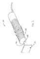
- FIG. 1 illustrates a perspective view of an inductive proximity sensor according at least one embodiment.
- FIG. 2 illustrates an end view of an inductive proximity sensor according to at least one embodiment.
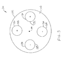
- FIG. 3 illustrates an end view of an inductive proximity sensor according to at least one embodiment.
- FIG. 4 illustrates an end view of an inductive proximity sensor according to at least one embodiment.
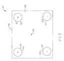
- FIG. 5 illustrates an end view of an inductive proximity sensor according to at least one embodiment.
- FIG. 6A illustrates a cross-sectional view of an inductive proximity sensor according to at least one embodiment.
- FIG. 6B illustrates a portion of an inductive proximity sensor according to at least one embodiment.
- FIG. 7 illustrates a flux simulation plot for an inductive proximity sensor according to at least one embodiment.
- Figure 1 illustrates an example of a proximity sensor 100 having an elongate cylindrical housing 102.
- the housing 102 can have a variety of shapes.
- the housing 102 can have a rectangular shape ( Figure 5 ), or a square shape, or other shapes.
- the housing 102 is defined in part by a longitudinal axis 106.
- Figures 6A and 6B illustrate an example of the sensor of Figure 1 , illustrating internal electronics, such as sensing circuitry 108.
- the sensing circuitry 108 is an inductive type of proximity sensor.
- the proximity sensor 100 further includes at least a first pair of inductive coils 120 electrically coupled with the sensing circuitry 108.
- the proximity sensor 100 further optionally includes a second pair of inductive coils 130.
- the coils 120, and optional coils 130, are located adjacent the face 104 of the housing 102, for instance, in an outer periphery of the housing 102.
- the coils 120 are, in an option, disposed in a position where the longitudinal axis of the coils 120 are substantially parallel with the longitudinal axis of the housing 102, and have substantially the same orientation as the housing 102.
- the first pair of inductive coils 120 include coils 122 and 124, where coils 122, 124 are separated to the extent possible for the dimensions of the face 104.
- the first pair of inductive coils 120 include coil 122 and coil 124, where the centers of coil 122 and coil 124 are opposite in polarity from one another, and are optionally connected in series. In another option, the coils 120 are connected in parallel. Options for the coils include, but are not limited to, bobbins with or without a core, or a printed circuit coil.
- the housing 102 includes face 104, which is defined in part by outer dimension D.
- the first pair of inductive coils 120 are separated from one another by more than 1 ⁇ 2 * D.
- a second pair of inductive coils 130 ( Figure 3 ), discussed below, are separated from one another by more than 1 ⁇ 2 * D, and/or a third pair of inductor coils 140 ( Figure 3 ) are separated from one another by more than 1 ⁇ 2 * D.
- a first pair of inductive coils 120 are disposed within the housing 102, for example on opposite sides of the longitudinal axis 106, and/or at an outer periphery of the housing 102.
- the center of coil 122 is opposite in polarity as the center of coil 124.
- the sensor 100 further optionally includes a second pair of inductive coils 130, including coil 132 and coil 134, where the center of coil 132 is opposite in polarity as the center of coil 134, for instance by connecting the coils 132, 134 in series. In another option, the coils 132, 134 are connected in parallel.
- coils 132, 134 are disposed on opposite sides of the longitudinal axis 106, and/or at an outer periphery of the housing 102. For instance, coils 132, 134 are separated to the extent possible for the dimensions of the face 104.
- the first pair of inductive coils 120 are disposed along a first axis
- the second pair of inductive coils 130 disposed along a second axis
- the first axis is orthogonal to the second axis, as shown in Figure 3 .
- the first pair of inductive coils 120 and the second pair of inductive coils 130 are electrically coupled with the electronics, and optionally each of the first pair of inductive coils are connected in series, and each of the second pair of inductive coils are connected in series.
- the coils can alternatively be connected in parallel.
- the sensor 100 further optionally includes a third pair of inductive coils 140, including coil 142 and coil 144, where coil 142 is opposite in polarity as coil 144.
- coils 142, 144 are disposed on opposite sides of the longitudinal axis 106, and/or optionally at an outer periphery of the housing 102.
- coils 142, 144 are separated to the extent possible for the dimensions of the face 104.
- the first set of coils 120 and the second set of coils 130 are symmetrical about the longitudinal axis 106.
- coils 142, 144 are disposed on opposite sides of the longitudinal axis 106.
- first set of coils 120 and the second set of coils 130 are symmetrical about the longitudinal axis 106.
- first set of coils 120, the second set of coils 130, and the third set of coils 140 are symmetrical about the longitudinal axis 106.
- an oscillator provides an oscillating signal to the first pair of inductive coils 120, which provides an electromagnetic field at a predetermined frequency.
- the electromagnetic field extends from the coils 120, optional coils 130, or optional coils 140 through the face 104.
- part of the sensing includes sending the signal to the first pair of inductive coils and the second pair of inductive coils 130, alternating between sending the signal to the first pair of inductive coils 120, and then to the second pair of inductive coils 130, to provide a symmetrical extended field. This can be accomplished, for instance, with a clock cycle output.
- the signal is also sent to the third set of inductive coils 140, where it alternates between the first, second and third set of inductive coils 120, 130, 140.
- the circuitry 108 also includes a detector circuit that analyzes the signal and provides an output signal indicative of the proximity (or lack thereof) of the object 112.
- the amplitude of the oscillator signal is evaluated to provide an output signal indicative of the presence or absence of the object 112 within the sensing range of the sensor 100.
- the output signal may be configured to provide a signal to external monitoring equipment and/or an appropriate indicator, such as a light emitting diode (LED) or a display.
- LED light emitting diode
- Figure 7 illustrates a flux simulation plot for a proximity sensor using the embodiments as discussed herein.
- the coil cross sections are shown as squares, and the "Y" coordinate on the plot is perpendicular to the face of the housing.
- the plot shows the oval-shaped extension of the flux pattern axial to the face of the housing. The extension of the flux pattern is due to canceling fields between the pair of coils which restricts return of flux lines between the coils, providing for extension of sensing distance from the face of the sensor housing..
Landscapes
- Switches That Are Operated By Magnetic Or Electric Fields (AREA)
- Electronic Switches (AREA)
Applications Claiming Priority (1)
| Application Number | Priority Date | Filing Date | Title |
|---|---|---|---|
| US11/864,545 US7994777B2 (en) | 2007-09-28 | 2007-09-28 | Apparatus and methods for an inductive proximity sensor |
Publications (2)
| Publication Number | Publication Date |
|---|---|
| EP2045922A1 true EP2045922A1 (de) | 2009-04-08 |
| EP2045922B1 EP2045922B1 (de) | 2011-03-30 |
Family
ID=40365212
Family Applications (1)
| Application Number | Title | Priority Date | Filing Date |
|---|---|---|---|
| EP08165350A Ceased EP2045922B1 (de) | 2007-09-28 | 2008-09-29 | Vorrichtung und Verfahren für einen induktiven Nähensensor |
Country Status (4)
| Country | Link |
|---|---|
| US (1) | US7994777B2 (de) |
| EP (1) | EP2045922B1 (de) |
| CN (1) | CN101533104B (de) |
| DE (1) | DE602008005820D1 (de) |
Cited By (1)
| Publication number | Priority date | Publication date | Assignee | Title |
|---|---|---|---|---|
| EP2511736A1 (de) * | 2011-04-15 | 2012-10-17 | iControls, k.s. | Vorrichtung und Verfahren zur Detektion von elektrisch leitfähigen Gegenständen |
Families Citing this family (9)
| Publication number | Priority date | Publication date | Assignee | Title |
|---|---|---|---|---|
| US8154278B2 (en) * | 2008-01-26 | 2012-04-10 | Pepperl+Fuchs, Inc. | Metal face inductive proximity sensor |
| US8188730B2 (en) * | 2008-09-10 | 2012-05-29 | Rockwell Automation Technologies, Inc. | Method and system for inductive proximity sensing that includes mounting effect compensation |
| FR2979712B1 (fr) * | 2011-09-02 | 2013-09-13 | Schneider Electric Ind Sas | Ensemble multicouche a double bobinage blinde pour detecteur inductif |
| US9791300B2 (en) * | 2014-02-20 | 2017-10-17 | Texas Instruments Incorporated | Inductive position-sensing |
| JP6900771B2 (ja) * | 2017-05-09 | 2021-07-07 | オムロン株式会社 | 近接センサおよび方法 |
| CN109781026B (zh) * | 2019-02-13 | 2021-12-03 | 业成科技(成都)有限公司 | 光学模组的安全监控方法及其应用于三维感测器 |
| DE102019103670B4 (de) * | 2019-02-13 | 2024-07-25 | Balluff Gmbh | Induktiver Sensor und Verfahren zu seinem Betrieb |
| US20220390642A1 (en) * | 2021-06-02 | 2022-12-08 | Nwave Technologies Inc | Battery-powered vehicle detecting device using an embedded inductive sensor |
| USD1110284S1 (en) * | 2024-07-18 | 2026-01-27 | Shenzhen Billda Technology Co., Ltd | Explosion-proof switch |
Citations (3)
| Publication number | Priority date | Publication date | Assignee | Title |
|---|---|---|---|---|
| DE10244104A1 (de) * | 2002-09-23 | 2004-04-01 | Wenglor Sensoric Gmbh | Induktiver Näherungsschalter |
| DE29724862U1 (de) * | 1996-09-18 | 2004-12-30 | Ifm Electronic Gmbh | Induktiver Näherungsschalter |
| DE102006040550A1 (de) * | 2005-08-31 | 2007-03-01 | Ifm Electronic Gmbh | Induktiver Näherungsschalter |
Family Cites Families (6)
| Publication number | Priority date | Publication date | Assignee | Title |
|---|---|---|---|---|
| DE69837694T2 (de) * | 1997-05-21 | 2008-01-10 | Sony Manufacturing Systems Corp., Kuki | Fühler für magnetisches Metall und Verfahren zum Detektieren eines magnetischen Metalls |
| DE19748602A1 (de) | 1997-11-04 | 1999-05-06 | Peine Salzgitter Verkehr | Achszählschalter |
| DE10057773B4 (de) | 2000-11-22 | 2021-05-27 | Werner Turck Gmbh & Co. Kg | Näherungsschalter |
| US7030626B2 (en) * | 2001-06-18 | 2006-04-18 | Yamatake Corporation | High-frequency oscillation type proximity sensor |
| AU2002330989A1 (en) * | 2001-08-03 | 2003-04-01 | Baker Hughes Incorporated | A method and apparatus for a multi-component induction instrumentmeasuring system |
| CN1279370C (zh) * | 2003-07-03 | 2006-10-11 | 石油大学(北京) | 测量井下套管内流体特性的探测器及探测系统 |
-
2007
- 2007-09-28 US US11/864,545 patent/US7994777B2/en active Active
-
2008
- 2008-09-28 CN CN2008101688691A patent/CN101533104B/zh not_active Expired - Fee Related
- 2008-09-29 DE DE602008005820T patent/DE602008005820D1/de active Active
- 2008-09-29 EP EP08165350A patent/EP2045922B1/de not_active Ceased
Patent Citations (3)
| Publication number | Priority date | Publication date | Assignee | Title |
|---|---|---|---|---|
| DE29724862U1 (de) * | 1996-09-18 | 2004-12-30 | Ifm Electronic Gmbh | Induktiver Näherungsschalter |
| DE10244104A1 (de) * | 2002-09-23 | 2004-04-01 | Wenglor Sensoric Gmbh | Induktiver Näherungsschalter |
| DE102006040550A1 (de) * | 2005-08-31 | 2007-03-01 | Ifm Electronic Gmbh | Induktiver Näherungsschalter |
Cited By (2)
| Publication number | Priority date | Publication date | Assignee | Title |
|---|---|---|---|---|
| EP2511736A1 (de) * | 2011-04-15 | 2012-10-17 | iControls, k.s. | Vorrichtung und Verfahren zur Detektion von elektrisch leitfähigen Gegenständen |
| WO2012140265A3 (de) * | 2011-04-15 | 2013-05-16 | Icontrols, K.S. | Vorrichtung und verfahren zur detektion von elektrisch leitfähigen gegenständen |
Also Published As
| Publication number | Publication date |
|---|---|
| US7994777B2 (en) | 2011-08-09 |
| US20090085560A1 (en) | 2009-04-02 |
| DE602008005820D1 (de) | 2011-05-12 |
| CN101533104B (zh) | 2012-07-18 |
| EP2045922B1 (de) | 2011-03-30 |
| CN101533104A (zh) | 2009-09-16 |
Similar Documents
| Publication | Publication Date | Title |
|---|---|---|
| US7994777B2 (en) | Apparatus and methods for an inductive proximity sensor | |
| US11486773B2 (en) | Non-contact magnetostrictive sensors and methods of operation of such sensors | |
| US10330499B2 (en) | Micro inductive sensor | |
| EP2031543A1 (de) | Vorrichtung zur Anordnung einer Radiofrequenzidentifikation (RFID) und entsprechendes Verfahren | |
| US6999007B2 (en) | Linear position sensor | |
| EP2554949A3 (de) | Elektromagnetischer Induktions-Absolutpositionierungs-Mess-Codierer | |
| EP2549239A3 (de) | Elektromagnetischer Induktions-Absolutpositionierungs-Mess-Codierer | |
| JP2009519592A (ja) | センサ | |
| JP2009500637A (ja) | 角度検出装置 | |
| CN103248133A (zh) | 无线电力传送装置 | |
| US9267921B2 (en) | Axial and circumferential flaw sensing eddy current probe | |
| CN109690232A (zh) | 非接触式传感器 | |
| US10866120B2 (en) | Sensor | |
| JP5575242B2 (ja) | 受動rfidタイヤ圧センサトランスポンダ用の磁場集中アンテナ | |
| WO2019219208A1 (en) | Foreign object detector, wireless power transmission system comprising a foreign object detector and method of detecting a foreign object | |
| US10488226B2 (en) | Proximity sensor | |
| US20200249372A1 (en) | Method and system for detecting a specific relative position between two objects | |
| CN107356887A (zh) | 一种球面型三轴磁通门探头 | |
| SE521228C2 (sv) | Markör för elektronisk artikelidentifiering, metod för att förse en sådan markör med en identitetskod samt en anordning för identifiering av markören | |
| US7994789B1 (en) | Dual field search coil for pulse induction metal detectors | |
| US10684385B2 (en) | Sensor having rotationally offset coil pairs and differently formed receiving coils for locating metal or magnetic objects | |
| US20110133727A1 (en) | Inductive Position Sensor | |
| EP2390193B1 (de) | Vorrichtung zur Prüfung der Anzahl der in einer Verpackungsschachtel übereinandergelegten Aluminiumverpackungsplatten | |
| CN212161524U (zh) | 一种用于无磁芯电感式接近开关的感应头 | |
| RU95105U1 (ru) | Индуктивный (трансформаторный) первичный измерительный преобразователь положения |
Legal Events
| Date | Code | Title | Description |
|---|---|---|---|
| PUAI | Public reference made under article 153(3) epc to a published international application that has entered the european phase |
Free format text: ORIGINAL CODE: 0009012 |
|
| AK | Designated contracting states |
Kind code of ref document: A1 Designated state(s): AT BE BG CH CY CZ DE DK EE ES FI FR GB GR HR HU IE IS IT LI LT LU LV MC MT NL NO PL PT RO SE SI SK TR |
|
| AX | Request for extension of the european patent |
Extension state: AL BA MK RS |
|
| 17P | Request for examination filed |
Effective date: 20091008 |
|
| 17Q | First examination report despatched |
Effective date: 20091103 |
|
| AKX | Designation fees paid |
Designated state(s): DE FR GB |
|
| GRAP | Despatch of communication of intention to grant a patent |
Free format text: ORIGINAL CODE: EPIDOSNIGR1 |
|
| GRAS | Grant fee paid |
Free format text: ORIGINAL CODE: EPIDOSNIGR3 |
|
| GRAA | (expected) grant |
Free format text: ORIGINAL CODE: 0009210 |
|
| AK | Designated contracting states |
Kind code of ref document: B1 Designated state(s): DE FR GB |
|
| REG | Reference to a national code |
Ref country code: GB Ref legal event code: FG4D |
|
| REF | Corresponds to: |
Ref document number: 602008005820 Country of ref document: DE Date of ref document: 20110512 Kind code of ref document: P |
|
| REG | Reference to a national code |
Ref country code: DE Ref legal event code: R096 Ref document number: 602008005820 Country of ref document: DE Effective date: 20110512 |
|
| PLBE | No opposition filed within time limit |
Free format text: ORIGINAL CODE: 0009261 |
|
| STAA | Information on the status of an ep patent application or granted ep patent |
Free format text: STATUS: NO OPPOSITION FILED WITHIN TIME LIMIT |
|
| 26N | No opposition filed |
Effective date: 20120102 |
|
| REG | Reference to a national code |
Ref country code: DE Ref legal event code: R097 Ref document number: 602008005820 Country of ref document: DE Effective date: 20120102 |
|
| REG | Reference to a national code |
Ref country code: FR Ref legal event code: PLFP Year of fee payment: 8 |
|
| REG | Reference to a national code |
Ref country code: FR Ref legal event code: PLFP Year of fee payment: 9 |
|
| REG | Reference to a national code |
Ref country code: FR Ref legal event code: PLFP Year of fee payment: 10 |
|
| REG | Reference to a national code |
Ref country code: FR Ref legal event code: PLFP Year of fee payment: 11 |
|
| PGFP | Annual fee paid to national office [announced via postgrant information from national office to epo] |
Ref country code: FR Payment date: 20200819 Year of fee payment: 13 Ref country code: GB Payment date: 20200819 Year of fee payment: 13 Ref country code: DE Payment date: 20200819 Year of fee payment: 13 |
|
| REG | Reference to a national code |
Ref country code: DE Ref legal event code: R119 Ref document number: 602008005820 Country of ref document: DE |
|
| GBPC | Gb: european patent ceased through non-payment of renewal fee |
Effective date: 20210929 |
|
| PG25 | Lapsed in a contracting state [announced via postgrant information from national office to epo] |
Ref country code: GB Free format text: LAPSE BECAUSE OF NON-PAYMENT OF DUE FEES Effective date: 20210929 Ref country code: FR Free format text: LAPSE BECAUSE OF NON-PAYMENT OF DUE FEES Effective date: 20210930 Ref country code: DE Free format text: LAPSE BECAUSE OF NON-PAYMENT OF DUE FEES Effective date: 20220401 |