EP2045978A2 - Netzwerkvorrichtung und Verfahren zur Änderung der Verbindungen von mindestens einem Benutzeranschluss an einen Dienst - Google Patents
Netzwerkvorrichtung und Verfahren zur Änderung der Verbindungen von mindestens einem Benutzeranschluss an einen Dienst Download PDFInfo
- Publication number
- EP2045978A2 EP2045978A2 EP08017261A EP08017261A EP2045978A2 EP 2045978 A2 EP2045978 A2 EP 2045978A2 EP 08017261 A EP08017261 A EP 08017261A EP 08017261 A EP08017261 A EP 08017261A EP 2045978 A2 EP2045978 A2 EP 2045978A2
- Authority
- EP
- European Patent Office
- Prior art keywords
- network device
- connection
- connections
- service
- modification
- Prior art date
- Legal status (The legal status is an assumption and is not a legal conclusion. Google has not performed a legal analysis and makes no representation as to the accuracy of the status listed.)
- Withdrawn
Links
Images

Classifications
-
- H—ELECTRICITY
- H04—ELECTRIC COMMUNICATION TECHNIQUE
- H04Q—SELECTING
- H04Q1/00—Details of selecting apparatus or arrangements
- H04Q1/02—Constructional details
- H04Q1/14—Distribution frames
- H04Q1/142—Terminal blocks for distribution frames
-
- H—ELECTRICITY
- H04—ELECTRIC COMMUNICATION TECHNIQUE
- H04Q—SELECTING
- H04Q1/00—Details of selecting apparatus or arrangements
- H04Q1/02—Constructional details
- H04Q1/14—Distribution frames
- H04Q1/145—Distribution frames with switches arranged in a matrix configuration
Definitions
- the present invention refers to a network device and to a modification method of the connections of at least an user socket to a service.
- one or more server cabinet and a telephone switchboard are present which are connected to each floor by means of a plurality of vertical connection cables.
- the cables besides can not be longer than 100 m for reasons of signal loss.
- connection cables are connected to network devices which for example an hub or a switch, known with the English terms “hub” and “switch”, which permit the connection a the sharing of services which the connection to the internet network or the connection to a local network in such a way to share hardware devices, data and software applications.
- network devices for example an hub or a switch, known with the English terms “hub” and “switch”, which permit the connection a the sharing of services which the connection to the internet network or the connection to a local network in such a way to share hardware devices, data and software applications.
- each floor Besides in each floor are present a plurality of user sockets for the connection for example of computers, telephones and other electronic devices.
- each user socket is connected to a patch panel by means of a horizontal patch cable.
- patch panels are connected to said network devices by means of a plurality of horizontal patch cables, known also with the English terms "patch cords”.
- a determined user socket is usable for example as data line or as telephone line.
- a disadvantage is that it is necessary a manual operation performed by an operator for modifying the connections of patch cables connected to that determined user socket.
- Another disadvantage is that this type of operation if frequently performed determines very high times and costs for the maintenance services, which often are higher than the costs of the components.
- Purpose of the present invention is that to realize a network device that permits the modification of the function of an user socket, for example from data socket to telephone socket, avoiding manual operations of modification of the connections of the horizontal patch cables, in particular of the horizontal patch cables that connect the patch panels to the network devices.
- Another purpose is that to realize a network device that avoid the manual intervention and the manual permutation of the patch cables which connect the network devices to the patch panels.
- Another purpose is that to realize a network device that avoid the necessity of the patch cables of connection between the network devices and the patch panels.
- Another purpose is that to realize a network device that permit the control and the modification of the connection between the network devices and the user sockets avoiding the necessity of a manual intervention on the same connection cables.
- Another purpose is that to realize a modification method of the connection of at least an user socket to a service which for example a data connection or a telephone connection that permit to avoid manual operations of modification and permutation of the patch cables which connect said at least an user socket to said service.
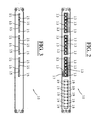
- a network device 10 comprising a plurality of input ports 13 of connection cables and a plurality of output ports 15 of connection cables.
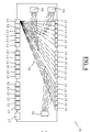
- said network device 10 comprises a programmable permutation circuit 30 integrated internally to the same which connect said plurality of input ports 13 to said plurality of output ports 15.
- said programmable permutation circuit 30 is a programmable permutation firmware circuit 30.
- said programmable permutation circuit 30 connect each input port 13 to said plurality of output ports 15 in particular by means of a correspondent plurality of electric connections which are electronically enabled and disabled in such a way to have an high transmission and receiving rate.
- this determines also the possibility to transmit without delay because the connections are electric, while the electronic activation and deactivation determines the possibility to program the connections between the plurality of input ports 13 and the plurality of output ports 15.
- connection to services which for example the connection to a data network or to a telephone network.
- said network device 10 is connected to a plurality of user sockets 90, and in particular it is also associated to a telephone switchboard 70 and it is connected to a modem 80 by means of a plurality of patch cables.
- user socket 90 it is meant a computer wall socket or a wall socket of a telephone or of other network devices and/or of control and management, as for example telephone switchboards, anti-theft and guard devices, entry phones and video entry phones, or a socket of an electronic device as for example a printer, a scanner, a fax, etc. connectable to the network.
- said network devices 10 comprises a permutation matrix stored internally to the same in a static memory of which the same is preferably provided.
- said network device 10 comprises configuration and modification electronic means 50, not shown, which are preferably associated to said programmable permutation circuit 30 in order to permit the configuration and the modification of a plurality of electric connections of the same.
- said configuration and modification electronic means 50 permit to electronically configure and to electronically modify the electrical connections between said plurality of input ports 13 and said plurality of output ports 15 of said network device 10.
- said configuration and modification electronic means 50 are associated also to a permutation matrix stored in a static memory of which said network device 10 is in particular provided, and besides said configuration and modification electronic means 50 permit the configuration and the modification of the same through a remote computer.
- said network device 10 comprises a plurality of electronic switches, shown in figure 4 , each of which is connected to each electric line of connection between each input port 13 and each output port 15, besides said electronic switches being electronically enabled and disabled in particular by means of said configuration and modification electronic means 50.
- said network device 10 comprises a patch panel integrated in the same.
- said network device 10 includes therefore also the functions and the features of a patch panel.
- said network device 10 includes a switch, that is a switch, integrated in the same.
- said network device 10 comprises a switch integrated with a patch panel.
- said switch is integrated in series with said patch panel.
- said switch is integrated in series with said patch panel by means of said programmable permutation circuit 30.
- said network devices 10 comprises a patch panel and a switch integrated between them in series by means of said programmable permutation circuit 30.
- said plurality of input ports 13 are a plurality of ports of said switch
- said plurality of output ports 15 are a plurality of ports of said patch panel suitable to be connected to a correspondent plurality of user sockets 90.
- said programmable permutation circuit 30 comprises a plurality of electrical connections which connect said plurality of input ports 13 of said switch and said plurality of output ports 15 of said patch panel.
- said plurality of electric connections are changeable, or they are electronically enabled and disabled, through the modification, also by means of a remote computer, of a permutation matrix stored internally to said network devices 10.
- said plurality of electric connections are configurable and changeable, or they are electronically enabled and disabled, through said configuration and modification electronic means 50.
- said plurality of input ports 13 is suitable to be connected to telephone cables and/or to data transmission cables and/or to audio/video receiving/transmission cables and/or receiving/transmission cables of signals of sensors.
- said plurality of input ports 13 comprises ports of type RJ45 and/or RJ11.
- said plurality of input ports 13 comprises ports comprises at least a connection port 17 to a further network device.
- connection port 17 is at least an optical connection port or of type RJ45.
- said network device 10 comprises a modem integrated internally to the same.
- said plurality of output ports 15 comprises a plurality of insulation displacement contacts in particular a plurality of contacts of type IDC for the connection preferably to data cables coming from correspondent user sockets 90.
- said network device 10 comprises releasable electric connection means, which are preferably integrated with said plurality of output ports 15, in such a way to quickly replace the electronic components internal to said network device 10 in case of damage or of an upgrading of the network device 10.
- said releasable electric connection means comprise a plurality of releasable electric connectors directly connected to said plurality of output ports 15.
- said network device 10 comprises a plurality of leds 19 (light emitting diodes) which are preferably connected to said plurality of output ports 15 in order to point out the activation and the functioning of each output port 15.
- leds 19 light emitting diodes
- user socket 90 it is meant a wall socket of a computer or a wall socket of a telephone or of other network devices and/or of control and management, which for example telephone switchboard, anti-theft and guard devices, entry phones and video entry phones, or a socket of an electronic device as for example a printer, a scanner, a fax, etc. connectable to the network.
- said modification method of the connections comprises the following phases:
- said at least an user socket 90 is a telephone socket
- said method comprises a phase of c) electronically disable/enable at least an electrical connection between at least an output port 15 and at least an input port 13 of said network device 10.
- said method comprises a phase of d) disable/enable through configuration and modification electronic means 50 at least an electric connection of a programmable permutation circuit 30 internal to a network device 10, said internal programmable permutation circuit 30 being connected to at least a least an input port 13 and to at least an output port 15 of said network device 10.
- said method comprises a phase of e) electronically enable/disable at a first predetermined time, in particular through electronic programmable means 50, at least an electrical connection between said at least an user socket 90 and a connection port to said service.
- said method comprises a phase of f) electronically disable/enable at a second predetermined time, in particular through electronic programmable means 50, at least an electric connection between said at least an user socket 90 and a connection port to said service.
- the network device and the modification method of the connections of at least an user socket to a service of the present invention thus conceived can undergo to numerous modifications and variations, all included in the same inventive concept.
Landscapes
- Engineering & Computer Science (AREA)
- Computer Networks & Wireless Communication (AREA)
- Devices For Checking Fares Or Tickets At Control Points (AREA)
- Telephonic Communication Services (AREA)
- Data Exchanges In Wide-Area Networks (AREA)
- Telephone Function (AREA)
Applications Claiming Priority (1)
| Application Number | Priority Date | Filing Date | Title |
|---|---|---|---|
| ITMI20071924 ITMI20071924A1 (it) | 2007-10-05 | 2007-10-05 | Dispositivo di rete e metodo di modifica dei collegamenti di almeno una presa utente ad un servizio |
Publications (2)
| Publication Number | Publication Date |
|---|---|
| EP2045978A2 true EP2045978A2 (de) | 2009-04-08 |
| EP2045978A3 EP2045978A3 (de) | 2010-07-21 |
Family
ID=40313776
Family Applications (1)
| Application Number | Title | Priority Date | Filing Date |
|---|---|---|---|
| EP08017261A Withdrawn EP2045978A3 (de) | 2007-10-05 | 2008-10-01 | Netzwerkvorrichtung und Verfahren zur Änderung der Verbindungen von mindestens einem Benutzeranschluss an einen Dienst |
Country Status (2)
| Country | Link |
|---|---|
| EP (1) | EP2045978A3 (de) |
| IT (1) | ITMI20071924A1 (de) |
Citations (3)
| Publication number | Priority date | Publication date | Assignee | Title |
|---|---|---|---|---|
| US5832071A (en) | 1995-11-24 | 1998-11-03 | Voelker Technologies, Inc. | Electronic patching system for telecommunications devices |
| US20010024906A1 (en) | 2000-02-24 | 2001-09-27 | Salmans Louis J. | Electronic patch panel apparatus and method of use |
| EP1746873A1 (de) * | 2005-07-18 | 2007-01-24 | Quinteck Electronics & Communications, Inc. | Modularer breitbandiger und bi-direktionaler programmierbarer Schalter mit im Betriebzustand austauschbaren Modulen |
-
2007
- 2007-10-05 IT ITMI20071924 patent/ITMI20071924A1/it unknown
-
2008
- 2008-10-01 EP EP08017261A patent/EP2045978A3/de not_active Withdrawn
Patent Citations (3)
| Publication number | Priority date | Publication date | Assignee | Title |
|---|---|---|---|---|
| US5832071A (en) | 1995-11-24 | 1998-11-03 | Voelker Technologies, Inc. | Electronic patching system for telecommunications devices |
| US20010024906A1 (en) | 2000-02-24 | 2001-09-27 | Salmans Louis J. | Electronic patch panel apparatus and method of use |
| EP1746873A1 (de) * | 2005-07-18 | 2007-01-24 | Quinteck Electronics & Communications, Inc. | Modularer breitbandiger und bi-direktionaler programmierbarer Schalter mit im Betriebzustand austauschbaren Modulen |
Also Published As
| Publication number | Publication date |
|---|---|
| ITMI20071924A1 (it) | 2009-04-06 |
| EP2045978A3 (de) | 2010-07-21 |
Similar Documents
| Publication | Publication Date | Title |
|---|---|---|
| US7217152B1 (en) | Patch panel with tracer | |
| US5130893A (en) | Signal distribution system | |
| JP2763274B2 (ja) | コネクタモジュール | |
| JP2012522433A (ja) | Rfidチップ技術を使用した相互接続構成用物理層管理 | |
| US7685349B2 (en) | Modules and backplanes | |
| US20160380397A1 (en) | High-density data communications cable | |
| EP3076682A1 (de) | Netzwerkelement | |
| US20040235356A1 (en) | Cross-connector for interfacing multiple communication devices | |
| EP2045978A2 (de) | Netzwerkvorrichtung und Verfahren zur Änderung der Verbindungen von mindestens einem Benutzeranschluss an einen Dienst | |
| US6415022B1 (en) | User programmable telephone wiring access terminal | |
| CA2548707C (en) | Tracer lamp arrangement | |
| KR101634125B1 (ko) | 통신장비연결용 판넬 | |
| US20180261965A1 (en) | High-density bridge adapter | |
| US20160353183A1 (en) | Communications interface | |
| EP2084916A2 (de) | Trennungspunkte in einem telekommunikationssystem | |
| US20070047526A1 (en) | Systems and methods for conecting between telecommunications equipment | |
| KR100844588B1 (ko) | 사무실용 아웃렛 허브 | |
| EP1135923B3 (de) | Signalverteilungseinrichtung zur verteilung und übermittlung von kommunikations- und multimediasignalen | |
| US7554818B2 (en) | Telecommunications module storage apparatus and method | |
| WO2007132162A1 (en) | Improvements in xdsl service provision | |
| US7987310B2 (en) | Self-configuring bus for connecting electronic devices | |
| US20080219282A1 (en) | Customer termination point in the subscriber premises of a telecommunication and/or data link and method for changing providers | |
| GB2426387A (en) | Switched connector for telecommunication system | |
| US8355497B2 (en) | Provision of telecommunication services | |
| CN1689290A (zh) | 智能集中器 |
Legal Events
| Date | Code | Title | Description |
|---|---|---|---|
| PUAI | Public reference made under article 153(3) epc to a published international application that has entered the european phase |
Free format text: ORIGINAL CODE: 0009012 |
|
| AK | Designated contracting states |
Kind code of ref document: A2 Designated state(s): AT BE BG CH CY CZ DE DK EE ES FI FR GB GR HR HU IE IS IT LI LT LU LV MC MT NL NO PL PT RO SE SI SK TR |
|
| AX | Request for extension of the european patent |
Extension state: AL BA MK RS |
|
| RTI1 | Title (correction) |
Free format text: NETWORK DEVICE AND MODIFICATION METHOD OF THE CONNECTIONS OF AT LEAST ONE USER SOCKET TO A SERVICE |
|
| PUAL | Search report despatched |
Free format text: ORIGINAL CODE: 0009013 |
|
| AK | Designated contracting states |
Kind code of ref document: A3 Designated state(s): AT BE BG CH CY CZ DE DK EE ES FI FR GB GR HR HU IE IS IT LI LT LU LV MC MT NL NO PL PT RO SE SI SK TR |
|
| AX | Request for extension of the european patent |
Extension state: AL BA MK RS |
|
| RIC1 | Information provided on ipc code assigned before grant |
Ipc: H04Q 1/14 20060101ALI20100617BHEP Ipc: H04Q 1/40 20060101AFI20100617BHEP |
|
| AKX | Designation fees paid |
Designated state(s): AT BE BG CH CY CZ DE DK EE ES FI FR GB GR HR HU IE IS IT LI LT LU LV MC MT NL NO PL PT RO SE SI SK TR |
|
| 17P | Request for examination filed |
Effective date: 20110429 |
|
| 17Q | First examination report despatched |
Effective date: 20121016 |
|
| STAA | Information on the status of an ep patent application or granted ep patent |
Free format text: STATUS: THE APPLICATION IS DEEMED TO BE WITHDRAWN |
|
| 18D | Application deemed to be withdrawn |
Effective date: 20140501 |
|
| REG | Reference to a national code |
Ref country code: DE Ref legal event code: R079 Free format text: PREVIOUS MAIN CLASS: H04L0012560000 Ipc: H04L0012700000 |
|
| REG | Reference to a national code |
Ref country code: DE Ref legal event code: R079 Free format text: PREVIOUS MAIN CLASS: H04L0012560000 Ipc: H04L0012700000 Effective date: 20141112 |