EP2046020A1 - Bildaufzeichnungsvorrichtung und Bildaufzeichnungsverfahren - Google Patents
Bildaufzeichnungsvorrichtung und Bildaufzeichnungsverfahren Download PDFInfo
- Publication number
- EP2046020A1 EP2046020A1 EP08253226A EP08253226A EP2046020A1 EP 2046020 A1 EP2046020 A1 EP 2046020A1 EP 08253226 A EP08253226 A EP 08253226A EP 08253226 A EP08253226 A EP 08253226A EP 2046020 A1 EP2046020 A1 EP 2046020A1
- Authority
- EP
- European Patent Office
- Prior art keywords
- image data
- image
- representative
- generating
- data
- Prior art date
- Legal status (The legal status is an assumption and is not a legal conclusion. Google has not performed a legal analysis and makes no representation as to the accuracy of the status listed.)
- Granted
Links
- 238000000034 method Methods 0.000 title claims abstract description 12
- 238000012545 processing Methods 0.000 claims description 35
- 230000006835 compression Effects 0.000 claims description 6
- 238000007906 compression Methods 0.000 claims description 6
- 238000009966 trimming Methods 0.000 claims description 6
- 150000001875 compounds Chemical class 0.000 description 22
- 238000012544 monitoring process Methods 0.000 description 22
- 230000006870 function Effects 0.000 description 17
- 230000015654 memory Effects 0.000 description 11
- 101000860173 Myxococcus xanthus C-factor Proteins 0.000 description 7
- 238000006243 chemical reaction Methods 0.000 description 7
- 238000010586 diagram Methods 0.000 description 6
- 238000001514 detection method Methods 0.000 description 4
- 238000013500 data storage Methods 0.000 description 3
- 230000010365 information processing Effects 0.000 description 3
- 239000003990 capacitor Substances 0.000 description 2
- 238000004891 communication Methods 0.000 description 2
- 238000012937 correction Methods 0.000 description 2
- 230000003287 optical effect Effects 0.000 description 2
- 238000005070 sampling Methods 0.000 description 2
- 230000003936 working memory Effects 0.000 description 2
- 238000004364 calculation method Methods 0.000 description 1
- 238000003384 imaging method Methods 0.000 description 1
- 230000001678 irradiating effect Effects 0.000 description 1
- 239000004973 liquid crystal related substance Substances 0.000 description 1
- 238000012423 maintenance Methods 0.000 description 1
- 239000003550 marker Substances 0.000 description 1
- 238000005259 measurement Methods 0.000 description 1
- 238000004091 panning Methods 0.000 description 1
- 238000002360 preparation method Methods 0.000 description 1
- 238000010187 selection method Methods 0.000 description 1
- 230000005236 sound signal Effects 0.000 description 1
- 229910052724 xenon Inorganic materials 0.000 description 1
- FHNFHKCVQCLJFQ-UHFFFAOYSA-N xenon atom Chemical compound [Xe] FHNFHKCVQCLJFQ-UHFFFAOYSA-N 0.000 description 1
Images


Classifications
-
- H—ELECTRICITY
- H04—ELECTRIC COMMUNICATION TECHNIQUE
- H04N—PICTORIAL COMMUNICATION, e.g. TELEVISION
- H04N1/00—Scanning, transmission or reproduction of documents or the like, e.g. facsimile transmission; Details thereof
- H04N1/21—Intermediate information storage
- H04N1/2166—Intermediate information storage for mass storage, e.g. in document filing systems
-
- H—ELECTRICITY
- H04—ELECTRIC COMMUNICATION TECHNIQUE
- H04N—PICTORIAL COMMUNICATION, e.g. TELEVISION
- H04N23/00—Cameras or camera modules comprising electronic image sensors; Control thereof
- H04N23/60—Control of cameras or camera modules
- H04N23/698—Control of cameras or camera modules for achieving an enlarged field of view, e.g. panoramic image capture
-
- H—ELECTRICITY
- H04—ELECTRIC COMMUNICATION TECHNIQUE
- H04N—PICTORIAL COMMUNICATION, e.g. TELEVISION
- H04N1/00—Scanning, transmission or reproduction of documents or the like, e.g. facsimile transmission; Details thereof
- H04N1/21—Intermediate information storage
- H04N1/2166—Intermediate information storage for mass storage, e.g. in document filing systems
- H04N1/2179—Interfaces allowing access to a plurality of users, e.g. connection to electronic image libraries
- H04N1/2187—Interfaces allowing access to a plurality of users, e.g. connection to electronic image libraries with image input from a plurality of different locations or from a non-central location, e.g. from one or more users
-
- H—ELECTRICITY
- H04—ELECTRIC COMMUNICATION TECHNIQUE
- H04N—PICTORIAL COMMUNICATION, e.g. TELEVISION
- H04N13/00—Stereoscopic video systems; Multi-view video systems; Details thereof
- H04N13/10—Processing, recording or transmission of stereoscopic or multi-view image signals
- H04N13/189—Recording image signals; Reproducing recorded image signals
-
- H—ELECTRICITY
- H04—ELECTRIC COMMUNICATION TECHNIQUE
- H04N—PICTORIAL COMMUNICATION, e.g. TELEVISION
- H04N13/00—Stereoscopic video systems; Multi-view video systems; Details thereof
- H04N13/20—Image signal generators
- H04N13/286—Image signal generators having separate monoscopic and stereoscopic modes
- H04N13/289—Switching between monoscopic and stereoscopic modes
-
- H—ELECTRICITY
- H04—ELECTRIC COMMUNICATION TECHNIQUE
- H04N—PICTORIAL COMMUNICATION, e.g. TELEVISION
- H04N23/00—Cameras or camera modules comprising electronic image sensors; Control thereof
- H04N23/60—Control of cameras or camera modules
- H04N23/63—Control of cameras or camera modules by using electronic viewfinders
-
- H—ELECTRICITY
- H04—ELECTRIC COMMUNICATION TECHNIQUE
- H04N—PICTORIAL COMMUNICATION, e.g. TELEVISION
- H04N5/00—Details of television systems
- H04N5/76—Television signal recording
- H04N5/765—Interface circuits between an apparatus for recording and another apparatus
- H04N5/77—Interface circuits between an apparatus for recording and another apparatus between a recording apparatus and a television camera
- H04N5/772—Interface circuits between an apparatus for recording and another apparatus between a recording apparatus and a television camera the recording apparatus and the television camera being placed in the same enclosure
-
- H—ELECTRICITY
- H04—ELECTRIC COMMUNICATION TECHNIQUE
- H04N—PICTORIAL COMMUNICATION, e.g. TELEVISION
- H04N13/00—Stereoscopic video systems; Multi-view video systems; Details thereof
- H04N2013/0074—Stereoscopic image analysis
- H04N2013/0088—Synthesising a monoscopic image signal from stereoscopic images, e.g. synthesising a panoramic or high resolution monoscopic image
-
- H—ELECTRICITY
- H04—ELECTRIC COMMUNICATION TECHNIQUE
- H04N—PICTORIAL COMMUNICATION, e.g. TELEVISION
- H04N2101/00—Still video cameras
-
- H—ELECTRICITY
- H04—ELECTRIC COMMUNICATION TECHNIQUE
- H04N—PICTORIAL COMMUNICATION, e.g. TELEVISION
- H04N2201/00—Indexing scheme relating to scanning, transmission or reproduction of documents or the like, and to details thereof
- H04N2201/32—Circuits or arrangements for control or supervision between transmitter and receiver or between image input and image output device, e.g. between a still-image camera and its memory or between a still-image camera and a printer device
- H04N2201/3201—Display, printing, storage or transmission of additional information, e.g. ID code, date and time or title
- H04N2201/3225—Display, printing, storage or transmission of additional information, e.g. ID code, date and time or title of data relating to an image, a page or a document
- H04N2201/3254—Orientation, e.g. landscape or portrait; Location or order of the image data, e.g. in memory
-
- H—ELECTRICITY
- H04—ELECTRIC COMMUNICATION TECHNIQUE
- H04N—PICTORIAL COMMUNICATION, e.g. TELEVISION
- H04N5/00—Details of television systems
- H04N5/76—Television signal recording
- H04N5/765—Interface circuits between an apparatus for recording and another apparatus
-
- H—ELECTRICITY
- H04—ELECTRIC COMMUNICATION TECHNIQUE
- H04N—PICTORIAL COMMUNICATION, e.g. TELEVISION
- H04N5/00—Details of television systems
- H04N5/76—Television signal recording
- H04N5/91—Television signal processing therefor
-
- H—ELECTRICITY
- H04—ELECTRIC COMMUNICATION TECHNIQUE
- H04N—PICTORIAL COMMUNICATION, e.g. TELEVISION
- H04N9/00—Details of colour television systems
- H04N9/79—Processing of colour television signals in connection with recording
- H04N9/7921—Processing of colour television signals in connection with recording for more than one processing mode
-
- H—ELECTRICITY
- H04—ELECTRIC COMMUNICATION TECHNIQUE
- H04N—PICTORIAL COMMUNICATION, e.g. TELEVISION
- H04N9/00—Details of colour television systems
- H04N9/79—Processing of colour television signals in connection with recording
- H04N9/80—Transformation of the television signal for recording, e.g. modulation, frequency changing; Inverse transformation for playback
- H04N9/82—Transformation of the television signal for recording, e.g. modulation, frequency changing; Inverse transformation for playback the individual colour picture signal components being recorded simultaneously only
- H04N9/8205—Transformation of the television signal for recording, e.g. modulation, frequency changing; Inverse transformation for playback the individual colour picture signal components being recorded simultaneously only involving the multiplexing of an additional signal and the colour video signal
- H04N9/8227—Transformation of the television signal for recording, e.g. modulation, frequency changing; Inverse transformation for playback the individual colour picture signal components being recorded simultaneously only involving the multiplexing of an additional signal and the colour video signal the additional signal being at least another television signal
Definitions
- the present invention relates to an image recording apparatus and an image recording method, and in particular, to an image recording apparatus and an image recording method of storing and recording a plurality of image data in one image file.
- Japanese Patent Application Laid-Open No. 2000-101916 discloses an electronic still camera which records a plurality of unit images, imaged so that parts may overlap, on a recording medium, and records a synthesized image, synthesized by connecting the unit images, on a recording medium.
- Japanese Patent Application Laid-Open No. 2005-311789 discloses a digital camera which synthesizes a plurality of rapid-shot image data to generate panoramic image data.
- Japanese Patent Application Laid-Open No. 2006-121229 discloses a stereo camera which synthesizes image data, imaged by two imaging units, to generate one panoramic image.
- Japanese Patent Application Laid-Open No. 2005-245018 discloses a camera which records a main image and a sub-image (e.g., a thinning image or a reduction image) in one image file.
- a sub-image e.g., a thinning image or a reduction image
- an aspect ratio of the image to be reproduced and an aspect ratio of a display screen of an image display device approximate each other.
- an aspect ratio of a display screen of an image display device differs every model. For example, image display devices with aspect ratio of 4:3 or those with aspect ratio of 16:9, which are horizontally longer than 4:3, have spread.
- the present invention was made in view of such a situation, and aims to provide an image recording apparatus and an image recording method which can output an image suitable for an aspect ratio of a display screen.
- an image recording apparatus includes: an image acquisition device which acquires a plurality of image data obtained by taking images in different viewing ranges; a connecting device which connects with an external display device to display and output the image data, and acquires attribute information including information on a display screen in the external display device to which the image data is output; a connection history recording device which records attribute information, acquired from the external display device connected through the connecting device, as connection history information; a generating condition determination device which determines a generating condition of representative image data according to the connection history information; a representative image generating device which generates representative image data according to the generating condition; and an image file generating device which generates an image file which includes the representative image data and a plurality of image data acquired by the image acquisition device.
- the image file of storing image data having different views and being obtained by panoramic shots it is possible to change a generating condition (aspect ratio) of a representative image according to connection history data of the external display device.
- the representative image data generating device synthesizes a plurality of image data, acquired by the above-mentioned image acquisition device, as the representative image data according to the connection history data to generate panoramic image data.
- the representative image data generating device selects one image among a plurality of image data, acquired by the image acquisition device, as the representative image data according to the connection history data.
- the representative image data generating device determines an aspect ratio of the representative image data on the basis of size information of the display screen of the external display device, which is recorded in the connection history data.
- the representative image data generating device synthesizes a plurality of image data, acquired by the image acquisition device, to generate panorama image data file as the representative image data when an aspect ratio of an external display device with most number of times of connection is about 16:9 or horizontally wider than 16:9 in the connection history data.
- the representative image data generating device synthesizes a plurality of image data, acquired by the image acquisition device, to generate panorama image data as the representative image data when an aspect ratio of an external display device connected finally is about 16:9 or horizontally wider than 16:9 in the connection history data.
- the representative image data generating device synthesizes a plurality of image data, acquired by the image acquisition device, to generate panorama image data as the representative image data when there are one or more external display devices whose aspect ratio is about 16:9 or horizontally wider than 16:9 in the connection history data.
- An image recording apparatus includes: an image acquisition device which acquires a plurality of image data obtained by taking images in different viewing ranges; a generating condition designation device which receives designation of a generating condition of representative image data; a representative image generating device which generates representative image data from the plurality of image data according to the generating condition; and an image file generating device which generates an image file which includes the representative image data and the plurality of image data acquired by the image acquisition device.
- the generating condition designation device receives designation of an aspect ratio of the representative image data.
- the image recording apparatus further includes: a selection device which selects whether image data for a display outputs is generated; an aspect ratio designation device which designate an aspect ratio of the image data for a display output; and an image generating device for a display output which generates image data for a display output.
- the representative image data generating device synthesizes a plurality of image data acquired by the image acquisition device, generates panoramic image data, and sets it as representative image data when the aspect ratio is set as 16:9, and selects representative image data from a plurality of image data, acquired by the image acquisition device, when the aspect ratio is set as 4:3;
- the image generating device for a display output performs predetermined processing to the representative image data to generate image data for a display output;
- the image file generating device stores the image data for a display output in the image file with the representative image data, and the plurality of image data acquired by the image acquisition device.
- the image generating device for a display output performs any processing of extension, compression, trimming, or padding to the selected image data to generate the image data for a display output.
- An image recording method includes: an image acquisition step of acquiring a plurality of image data obtained by taking images in different viewing ranges; a connecting step of connecting with an external display device to display and output the image data, and acquiring attribute information including information on a display screen in the external display device to which the image data is output; a connection history recording step of recording attribute information, acquired from the external display device connected through the connecting step, as connection history information; a generating condition determination step of determining a generating condition of representative image data according to the connection history information; a representative image generating step of generating representative image data according to the generating condition; and an image file generating step of generating an image file which includes the representative image data and the plurality of image data acquired at the image acquisition step.
- An image recording method includes: an image acquisition step of acquiring a plurality of image data obtained by taking images in different viewing ranges; a generating condition designation step of receiving designation of a generating condition of representative image data; a representative image generating step of generating representative image data from the plurality of image data according to the generating condition; and an image file generating step of generating an image file which includes the representative image data and the plurality of image data acquired at the image acquisition step.
- an image file of storing image data having different views and being obtained by panoramic shots it is possible to change a generating condition (aspect ratio) of a representative image according to connection history data or setting of an external display device.
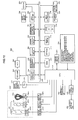
- Fig. 1 is a block diagram showing main configuration of an image pickup apparatus (compound eye camera) comprising an image recording apparatus according to a first embodiment of the present invention.
- a image pickup apparatus 10 is a compound eye camera comprising a plurality of image pickup units 12R and 12L, and is an apparatus which acquires parallax images obtained by photographing the same subject from a plurality of viewpoints, and records the parallax images as an image file for recording in a predetermined form.
- the image pickup units may be two or more.
- a main CPU 14 (hereinafter, this is called a CPU 14) performs integrated control of operations of the whole compound eye camera 10 according to a predetermined control program on the basis of an input from an operation unit 16.
- ROM 24, EEPROM 26, and working memory 28 are connected to the CPU 14 through a system bus 22.
- Various data required for a control program, control, and the like which the CPU 14 executes is stored in the ROM 24.
- Various setting information on operations of the compound eye cameras 10 such as user setting information is stored in the EEPROM 26.
- the working memory 28 includes an arithmetic operation area of the CPU 14, and a temporary storage of image data.
- An image display unit 50 is constructed of, for example, a display unit comprising a color liquid crystal panel, and is used as GUI (Graphical User Interface) at the time of various settings while being used as an image display unit for displaying a picked-up image.
- GUI Graphic User Interface
- the image display unit 50 is used as an electronic finder for checking an angle of view at the time of an image pickup mode.
- the image display unit 50 can display a three-dimensional image (3D image).
- the operation unit 16 includes operational input units, such as a power supply/mode switch, a mode dial, a release switch, a cross key, a zoom button, a MENU/OK button, a DISP button, and a BACK button.
- operational input units such as a power supply/mode switch, a mode dial, a release switch, a cross key, a zoom button, a MENU/OK button, a DISP button, and a BACK button.
- the power supply/mode switch is a unit for switching ON and OFF of a power supply of the compound eye camera 10, and switching an operation mode (reproduction mode and image pickup mode) of the compound eye camera 10.
- the mode dial is an operation unit for switching the image pickup mode of the compound eye camera 10, according to a setting position of the mode dial, the image pickup mode is switched among a panoramic shot mode for taking a panoramic image, a 2D still image pickup mode for taking a two-dimensional still image, a 2D moving image pickup mode for taking two-dimensional moving images, a 3D still image pickup mode for taking a three-dimensional still image, and a 3D moving image pickup mode for taking three-dimensional moving images.
- a flag which shows that it is in panoramic shot mode is set in the image pickup mode control flag 30.
- the image pickup mode When the image pickup mode is set as the 2D still image pickup mode or 2D moving image pickup mode, a flag which shows that it is in the 2D mode for taking a two-dimensional image is set in the image pickup mode control flag 30.
- a flag which shows that it is in the 3D mode for taking a three-dimensional image is set in the image pickup mode control flag 30.
- the CPU 14 discriminates setting of the image pickup mode with reference to the image pickup mode control flag 30.
- the release switch is constructed of a two-step stroke type switch constructed of so-called "half press” and "full press".
- image pickup preparation processing namely, AE (Automatic Exposure), AF (Auto Focus), and AWB (Automatic White Balance)
- AE Automatic Exposure
- AF Automatic Focus
- AWB Automatic White Balance
- a release switch for a still image pickup, and a release switch for a moving image pickup may be provided separately.
- the cross key is an operation unit which is made it possible to be pressed and operated in four directions, that is, the up, down, left, and right, and functions are assigned to respective directional buttons according to the operation mode of the compound eye camera 10. For example, at the time of the image pickup mode, a function of switching ON and OFF of a macro function is assigned to the left button, and a function of switching a flash mode to the right button is assigned. In addition, at the time of the image pickup mode, a function of changing brightness of the image display unit 50 is assigned to the up button, and a function of switching ON/OFF of a self-timer is assigned to the down button.
- a function of frame advance is assigned to the left button and a function of frame back is assigned to the right button. Furthermore, at the time of the reproduction mode, a function of changing brightness of the image display unit 50 is assigned to the up button, and a function of deleting a reproducing image is assigned to the down button. Moreover, at the time of various settings, a function of moving a cursor displayed on the image display unit 50 in a direction of each button is assigned.
- the zoom button is an operation unit for performing zooming operations of the image pickup units 12R and 12L, and comprises a tele zoom button which specifies zooming to a telephoto side, and a wide zoom button which specifies the zooming to a wide-angle side.
- the MENU/OK button is used for decision of selection content, an execution instruction (O.K. function) of processing, and the like while being used for a call (MENU function) of a menu screen, and an assigned function is switched according to a set state of the compound eye camera 10.
- the MENU/OK button sets all the adjustment items which the compound eye camera 10 has, all the adjustment items including, for example, an exposure value, a tint, ISO speed, picture quality adjustment such as a record pixel count, setup of the self-timer, switching of a metering system, use/no use of digital zoom, and the like.
- the compound eye camera 10 operates according to a condition set on this menu screen.
- the DISP button is used for an input of a switching command of display content of the image display unit 50, and the like and the BACK button is used for an input of a command for cancel of an input operation, and the like.
- An image pickup lens 60 comprises a zoom lens, a focus lens, and a diaphragm.
- the zoom lens and focus lens move forward and backward along an optical axis (LR and LL in the figure) of each image pickup unit.
- the CPU 14 controls a position of the zoom lens to perform zooming by controlling drive of a zoom actuator, not shown, through a photometric and ranging CPU 80, and controls a position of the focus lens to perform focusing by controlling drive of a focus actuator through the photometric and ranging CPU 80.
- the CPU 14 controls an opening amount (f-stop number) of a diaphragm to control incident light quantity to an image pickup element 62, by controlling drive of a diaphragm actuator through the photometric and ranging CPU 80.
- the CPU 14 When taking images of a plurality of viewpoints at the time of the panoramic shot mode or 3D mode, the CPU 14 synchronizes and drives image pickup lenses 60R and 60L of the respective image pickup units 12R and 12L. That is, the image pickup lenses 60R and 60L are set at the always same focal length (zoom magnifying power). In addition, the apertures are adjusted so as to become always the same incident light quantity (f-stop number). Furthermore, in the 3D mode, focusing is performed so that always the same subject may be focused.
- a flash light emitting unit 76 includes, for example, a discharge tube (xenon tube) and emits light if needed, that is, in the case of taking an image of a dark subject, backlight, or the like.
- a charge/emission control unit 78 includes a main capacitor for supplying a current for making the flash light emitting unit 76 emit a light.
- the CPU 14 transmits a flash light emission command to the photometric and ranging CPU 80, and performs charge control of the main capacitor, and control of timing of discharge (light emission), discharge duration, and the like of the flash light emitting unit 76.
- a light emitting diode may be used as the flash light emitting unit 76.
- the image pickup unit 12 comprises a light emitting element 86 (e.g., light emitting diode) for ranging for irradiating a subject, and an image pickup element 84 for ranging which takes an image (image for ranging) of the subject which is irradiated by the above-mentioned light emitting element 86 for ranging.
- a light emitting element 86 e.g., light emitting diode
- an image pickup element 84 for ranging which takes an image (image for ranging) of the subject which is irradiated by the above-mentioned light emitting element 86 for ranging.
- the photometric and ranging CPU 80 controls the image pickup element 84 for ranging to make it take an image for ranging while making the light emitting element 86 for ranging emit light in predetermined timing on the basis of a command from the CPU 14.
- the image for ranging taken by the image pickup element 84 for ranging is converted into digital data by an A/D converter 96, and is inputted into a range information processing circuit 98.
- the range information processing circuit 98 calculates a distance (subject distance) between a subject, which is taken by the image pickup units 12R and 12L, and the compound eye camera 10 on the basis of a so-called principle of trigonometrical survey using the image for ranging acquired from the image pickup element 84 for ranging.
- the subject distance calculated by the range information processing circuit 98 is recorded in a range information record circuit 100.
- a TOF (Time of Flight) method of calculating the subject distance from light flight time (lag time) when light radiated from the light emitting element 86 for ranging is reflected by a subject and reaches the image pickup element 84 for ranging, and speed of light may be used.
- the image pickup unit 12 comprises a space/angle of convergence driving circuit 88, and a space/angle of convergence detection circuit 90.
- the space/angle of convergence driving circuits 88R and 88L drive the image pickup units 12R and 12L, respectively.
- the CPU 14 operates the space/angle of convergence driving circuits 88R and 88L through a space/angle of convergence control circuit 92 to adjust a space and an angle of convergence between the image pickup lenses 60R and 60L.
- the space/angle of convergence detection circuits 90R and 90L include, for example, a unit of transmitting and receiving an electric wave.
- the CPU 14 measures the space and angle of convergence between the image pickup lenses 60R and 60L by operating the space/angle of convergence detection circuits 90R and 90L through the space/angle of convergence control circuit 92, so that the space/angle of convergence detection circuits 90R and 90L transmit and receive an electric wave mutually.
- the measurements of the space and angle of convergence between the image pickup lenses 60R and 60L are stored in a lens space and angle of convergence memory circuit 102.
- the image pickup element 62 is constructed of a color CCD solid-state image pickup element, for example.
- a light-receiving surface of the image pickup element 62 many photodiodes are arranged two-dimensionally and the trichromatic (R, G, B) light filter is arranged in predetermined arrangement on each of the photodiodes.
- An optical image of a subject imaged on the light-receiving surface of the image pickup element 62 with the image pickup lens 60 is converted into signal charges according to incident light quantity by these photodiodes.
- the signal charges stored in respective photodiodes are read from the image pickup element 62 one by one as voltage signals (R, G, and B signals) according to the signal charges on the basis of driving pulses given from a TG 64 according to a command of the CPU 14. Since the image pickup element 62 comprises an electronic shutter function, exposure time (shutter speed) is controlled by controlling charge storage time to the photodiodes.
- an image pickup element other than a CCD such as a CMOS sensor, can be also used.
- An analog signal processor 66 includes a correlative double sampling circuit (CDS) for removing reset noise (low frequency) included in the R, G, and B signals outputted from the image pickup element 62, and an AGS circuit for amplifying the R, G, and B signals and controls them in a constant level of amplitude.
- the analog R, G, and B signals outputted from the image pickup element 62 are amplified by an analog signal processor 66 while being given correlative double sampling processing.
- the analog R, G, and B signals outputted from the analog signal processor 66 are converted into digital R, G, and B signals to be inputted into an image input controller (buffer memory) 70 by an A/D converter 68.
- a digital signal processor 72 includes a synchronization circuit (processing circuit of interpolating spatial shifts of carrier chrominance signals accompanying a color filter array of a single plate CCD and converting the carrier chrominance signals into a simultaneous type), a white balance adjustment circuit, a gradation conversion processing circuit (gamma corrector), a contour correction circuit, a luminance and color differential signal generating circuit, and the like.
- the digital R, G, and B signals inputted into the image input controller 70 are converted into a Y/C signal which is constructed of a luminance signal (Y signal) and color difference signals (Cr and Cb signals) while being given predetermined processing, such as synchronization processing, white balance adjustment, gradation conversion, and contour correction, by the digital signal processor 72.
- a live view image (pass-through image) on the image display unit 50
- sequential supply of the Y/C signal generated in the digital signal processor 72 is performed to buffer memory 44.
- a display controller 42 reads the Y/C signal supplied to the buffer memory 44, and outputs it to the YC-RGB conversion unit 46.
- the YC-RGB conversion unit 46 converts into R, G, and B signals the Y/C signal inputted from the display controller 42, and outputs them to the image display unit 50 through a driver 48. Thereby, a through image is displayed on the image display unit 50.
- a final image file (image file recorded at the end) recorded on a memory card 40 is read, is extended into a non-compressed Y/C signal by a compression and extension processor 74, and thereafter, is inputted into the buffer memory 44.
- the display controller 42 reads the Y/C signal supplied to the buffer memory 44, and outputs it to the YC-RGB conversion unit 46.
- the YC-RGB conversion unit 46 converts into R, G, and B signals the Y/C signal inputted from the display controller 42, and outputs them to the image display unit 50 through the driver 48. Thereby, an image file recorded in the memory card 40 is displayed on the image display unit 50.
- the compound eye camera 10 comprises an HDMI I/F (High-Definition Multimedia Interface) 52.
- a reproduction device e.g., a television set or a monitor
- R, G, and B signals generated in the YC-RGB conversion unit 46 are outputted to the reproduction device 150.
- R, G, and B signals generated in the YC-RGB conversion unit 46 are outputted to the reproduction device 150.
- An image for recording is taken by one predetermined image pickup unit (e.g., 12R) at the time of the 2D mode.
- the image taken by the image pickup unit 12R is compressed by the compression and extension processor 74R.
- This compressed image data is recorded in the memory card 40 as an image file in a predetermined format through a memory controller 34 and an interface unit (I/F) 38.
- a still image is recorded in JPEG (Joint Photographic Experts Group) and moving images are done in MPEG-2 or MPEG-4, that is, as a compressed image file in conformity with the H.264 standard.
- images are taken by the image pickup units 12R and 12L synchronously.
- AF processing and AE processing are performed on the basis of an image signal acquired by either of the image pickup units 12R and 12L.
- two viewpoints of images taken by the respective image pickup units 12R and 12L are compressed by the compression and extension processors 74R and 74L respectively, and are stored in one 3D image file (multi-page file) to be recorded in the memory card 40.
- subject distance information and information on a space and an angle of convergence of the image pickup lenses 60R and 60L are stored in the 3D image file with the two viewpoints of compressed image data.
- the recording processing of images taken in the panoramic shot mode will be described.
- two viewpoints of images are taken synchronously by the image pickup units 12R and 12L.
- the AF processing and AE processing are performed on the basis of an image signal acquired by either of the image pickup units 12R and 12L.
- two viewpoints of images taken by the respective image pickup units 12R and 12L are compressed by the compression and extension processors 74R and 74L respectively, and are stored in one panoramic image file (multi-page file) to be recorded in the memory card 40.
- representative image data, subject distance information, and information on a space and an angle of convergence of the image pickup lenses 60R and 60L are stored in the panoramic image file with the two viewpoints of compressed image data.
- the CPU 14 acquires attribute information of the reproduction device 150, and records the attribute information (connection history) of the reproduction device 150, having been connected in the past, on the connection history manager 54. Then, the CPU 14 determines size (aspect ratio) of the representative image data stored in the panoramic image file on the basis of this connection history.
- the acquisition methods of the attribute information of the reproduction device 150 include a system called Display Data Channel (DDC) which VESA (Video Electronics Standards Association) defined.
- DDC Display Data Channel
- VESA Video Electronics Standards Association
- the attribute information which includes a resolution of a display screen of the reproduction device 150 is transmitted in a data format of Extended Display Identification Data (EDID) from the reproduction device 150 to the compound eye camera 10.
- EDID Extended Display Identification Data
- Table 1 shows connection history data. As shown in Table 1, as the attribute information of the reproduction device 150, the date and hour when the reproduction device 150 was connected, the resolution (aspect ratio) of a display screen of the connected reproduction device 150, and identification information (e.g., model name) of the reproduction device 150 are recorded from the left of Table 1.
- Fig. 2 is a flowchart showing a flow of recording processing of the connection history of the reproduction device 150.
- the attribute information of the reproduction device 150 is acquired (step S12).
- the connection date and hour, the resolution (aspect ratio) of the display screes of the reproduction device 150, and the identification information of the reproduction device 150 are recorded in the connection history manager 54 (step S16).
- Fig. 3 is a flowchart showing a flow of generation processing of a panoramic image file.
- connection history data is read from the connection history manager 54 (step S22).
- connection history data does not fulfill a predetermined condition (No at step S24)
- predetermined viewpoint image data is selected as a representative image (step S26).
- the connection history data fulfills the predetermined condition (Yes at step S24)
- two viewpoints of image data taken by the image pickup units 12R and 12L is synthesized, panoramic image data wider than the viewpoint image data is generated, and it is set as representative image data (step S28).
- the representative image data is stored, the panoramic image file in the multi-page format in which respective viewpoint image data is stored as sub-image data is generated, and is recorded in the memory card 40 (step S30).
- step S24 when it is supposed to be outputted on a wide display screen (e.g., in one case of any one among (a) a case that an aspect ratio of a reproduction device with a largest number of times of connection is wider than about 16:9 or horizontally wider than 16:9 in the connection history data of Table 1, (b) a case that an aspect ratio of a reproduction device connected at the end is about 16:9 or horizontally wider than 16:9, and (c) a case that the number of reproduction devices whose aspect ratios are about 16:9 or horizontally wider than 16:9 is one or more in the connection history), wide panoramic image data is made to be representative image data (step S28).
- a wide panoramic image data is made to be representative image data (step S28).
- one image data among the viewpoint image data is set as representative image data (step S26).
- the conditions of judgment at step S24 are not limited to the above, for example, when at least one of the above-mentioned conditions (a), (b), and (c) is fulfilled (condition (d)), the wide panoramic image data may be made to be representative image data (step S28), and when the above-mentioned condition (d) is not fulfilled, one image data among the viewpoint image data may be set as representative image data (step S26).
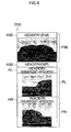
- Fig. 4 is a drawing showing a panoramic image file which includes panoramic image data as a representative image.
- representative image data P10 and right and left viewpoint image data PL and PR taken by the image pickup units 12L and 12R is included in a panoramic image file D10 in order.
- the representative image data P10 is wide (e.g., 16:9) panoramic image data which is synthesized by superposing parts of left and right viewpoint image data PL and PR.
- reference numerals H10, HL, and HR in the drawing denote header information (Exif tag information) applied to the representative image data P10, and the viewpoint image data PL and PR, respectively.
- reference numeral H12 denotes a header including a marker which shows a recording place (address) of the viewpoint image data PL and PR in a panoramic image file.
- Fig. 5 is a drawing showing a panoramic image file which includes one of viewpoint image data among a plurality of viewpoint image data, as a representative image.
- Three viewpoints of image data PL, PC, and PR is included in a panoramic image file D20 shown in Fig. 5 , and an image file taken by a central viewpoint of image pickup unit among these is stored as representative image data P20.
- the representative image data P20 for example, an image, taken by an image pickup unit whose view position is middle or near the middle, among viewpoint image data, or image data taken by an image pickup unit in a side of user's dominant eye (e.g., default setting is a right eye) among a middle or nearly middle viewpoint of image data is selected.
- reference numeral H20 in the drawing denotes header information (Exiftag information) applied to the representative image data P20.
- connection history data that an image is outputted to a reproduction device 150 with a wide display screen
- wide panoramic image data since it is made that wide panoramic image data is stored as a representative image, it is possible to record an image suitable for an aspect ratio of the display screen of the reproduction device 150 which is an output destination.
- a generating condition of a representative image file is set manually.
- Fig. 7 is a flowchart showing generation processing of image data for monitoring.
- step S40 when images are taken in the panoramic shot mode and two viewpoints of image data is acquired (step S40), it is judged whether setting of an image for monitoring is set as "Existence of image for monitoring" (step S42).
- step S42 In a setting screen of an image for monitoring shown in Fig. 8 , when it is set as "Nonexistence of image for monitoring" (No at step S42), one among viewpoint image data is selected as representative image data (step S44). Then, while the representative image data is stored, a panoramic image file in the multi-page format in which respective viewpoint image data is stored as sub-image data is generated, and is recorded in the memory card 40 (step S46).
- step S44 similarly to the above-mentioned embodiment, as the representative image data, for example, an image, taken by an image pickup unit whose view position is middle or near the middle, among viewpoint image data, or image data taken by an image pickup unit in a side of user's dominant eye (e.g., default setting is a right eye; however a user can arbitrarily set the dominant eye) among a middle or nearly middle viewpoint of image data is selected.
- a side of user's dominant eye e.g., default setting is a right eye; however a user can arbitrarily set the dominant eye
- step S42 when recording setting of an image for monitoring is set as "Existence of image for monitoring"(Yes at step S42) and an aspect ratio of the image for monitoring is set at 4:3 (No at step S48), one among viewpoint image data is selected as representative image data (step S50).
- the selection method of the representative image data at step S50 is the same as that at step S44.
- predetermined processing e.g., at least one processing among enlargement, reduction, trimming, and padding
- predetermined processing is given to the representative image data selected at step S42 for an image for monitoring with an aspect ratio of about 4:3 is generated (step S52).
- a panoramic image file in the multi-page format in which representative image data, image data for display, and respective viewpoint image data are stored is generated, and is recorded in the memory card 40 (step S46).
- step S48 when the aspect ratio of an image for monitoring is set at 16:9 at step S48, two viewpoints of image data taken by the image pickup units 12R and 12L is synthesized, panoramic image data wider than the viewpoint image data is generated, and it is set as representative image data (step S54).
- predetermined processing e.g., at least one processing among enlargement, reduction, trimming, and padding
- predetermined processing is given to the representative image data generated at step S54 for an image for monitoring with an aspect ratio of about 16:9 is generated (step S56).
- a panoramic image file in the multi-page format in which representative image data, image data for display, and respective viewpoint image data are stored is generated, and is recorded in the memory card 40 (step S46).
- FIGs. 9A to 9E are drawings showing data structure of a panoramic image file according to the second embodiment of the present invention. As shown in Fig. 9A , a representative image data storage area A40 and sub-image data storage area A42 are provided in a panoramic image file D40.
- Image data PM for monitoring is stored in a top of the sub-image data storage area A42.
- the image data PM for monitoring is generated by giving the predetermined processing (e.g., at least one processing among enlargement, reduction, trimming, and padding) to the representative image data P40 according to the aspect ratio set on the setting screen of an image for monitoring in Fig. 8 .
- predetermined processing e.g., at least one processing among enlargement, reduction, trimming, and padding
- the aspect ratio of image data PM for monitoring when the aspect ratio of image data PM for monitoring is set at 4:3, representative image data becomes the same size as that of viewpoint image data (1600 x 1200), and the size of the image data for monitoring is set at 640 x 480, for example.
- representative image data when the aspect ratio of image data PM for monitoring is set at 16:9, representative image data becomes panoramic size (3600 x 1200) which is wider than viewpoint image data (1600 x 1200), and the size of the image data for monitoring becomes 1920 x 1080, for example.
- image data for monitoring and representative image data it is possible to set aspect ratios of image data for monitoring and representative image data manually, and to record the representative image data according to display screen size and an aspect ratio of the reproduction device 150 which is an output destination.
- processing of generating image data for monitoring from representative image data is omissible by storing in panoramic image data the image data for monitor display, whose pixel count is dropped, in addition to representative image data.
- the image recording apparatus according to the present invention is also applicable to a single-lens camera or an image processing device like a personal computer.
- Fig. 10 is a block diagram showing main configuration of a single-lens camera comprising the image recording apparatus according to the present invention.
- a single-lens camera 200 comprises, for example, an HDMI I/F 260 and a connection history manager 262.
- an image pickup mode is set in the panoramic shot mode, and, for example, still images are rapidly shot with moving the single-lens camera horizontally (panning).
- a CPU 202 synthesizes a plurality of image data rapidly shot at the time of the panoramic shot mode to generate panoramic image data.
- the image recording apparatus of the present invention is achievable by executing the processing shown in above-mentioned Figs. 2 , 3 , and 7 to a plurality of viewpoint image data rapidly shot in the panoramic shot mode.
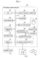
- Fig. 11 is a block diagram showing main configuration of an image recording apparatus according to a fourth embodiment of the present invention.
- an image recording apparatus 300 is constructed of, for example, a personal computer (PC), and is an apparatus for performing reading of an image file for recording from an image pickup apparatus or a memory card 314, maintenance and edit of the image file for recording, and the like.
- a central processing unit (CPU) 302 is connected to respective blocks in the image recording apparatus 300 through a bus 304, and controls operations of the respective blocks.
- Main memory 306 includes a storage area where a control program is stored, and a workspace at the time of program execution.
- a hard disk drive 308 stores an operating system (OS) and various kinds of application software of the image recording apparatus 300, a plurality of viewpoints of image data read from the image pickup apparatus or memory card 314, and the like.
- a CD-ROM drive 310 reads data from CD-ROM which is not shown.
- a card interface unit (card I/F) 312 reads image data in the memory card 314.
- Display memory 316 temporarily stores data for display.
- a monitor 318 is constructed of, for example, a CRT (Cathode Ray Tube) monitor or an LCD monitor, and displays an image, a character, and the like on the basis of image data, character data, and the like which are outputted from this display memory 316.
- the display memory 316 and monitor 318 are connected via any interface of Dsub-15, DVI, and HDMI.
- a keyboard 320 and a mouse 322 receive an operation input from an operator and inputs a signal according to the operation input into the CPU 302.
- a pointing device a touch panel, a touchpad, or the like can be used besides the mouse 322.
- a mouse controller 324 detects a state of the mouse 322, and outputs signals of such as a position of a mouse pointer on the monitor 318, and a state of the mouse 322 to the CPU 302.
- An audio input/output circuit 326 to which a microphone 328 and a speaker 330 are connected and various kinds of sound signals are inputted reproduces and outputs various kinds of operation sound according to an operation input from the keyboard 320 or the like.
- a communication interface unit (communication I/F) 332 communicates with a network NW.
- a camera connecting interface unit (camera connection I/F) 334 transmits and receives data between with an image pickup apparatus (the compound eye camera 10, or single-lens camera 200).
- the image recording apparatus 300 can achieve the image recording apparatus of the present invention by giving the processing shown in the above-mentioned Figs. 2 , 3 , and 7 to the viewpoint image data concerned when a plurality of viewpoint image data, obtained by a panoramic shot, through the memory card 314 or image pickup apparatus (the compound eye camera 10 or single-lens camera 200) is acquired.
- the present invention can be provided also as a program applied to an image recording apparatus such as an image pickup apparatus, a personal computer, a personal digital assistant, and an image storage unit.
- an image recording apparatus such as an image pickup apparatus, a personal computer, a personal digital assistant, and an image storage unit.
- the present invention can be provided also as a recording medium on which the program described above is recorded.
- the program is installed on a device using the recording medium so that the device may realize the apparatus according to the present invention.
Landscapes
- Engineering & Computer Science (AREA)
- Multimedia (AREA)
- Signal Processing (AREA)
- Library & Information Science (AREA)
- Television Signal Processing For Recording (AREA)
- Studio Devices (AREA)
- Editing Of Facsimile Originals (AREA)
- Image Processing (AREA)
- Testing, Inspecting, Measuring Of Stereoscopic Televisions And Televisions (AREA)
Applications Claiming Priority (1)
| Application Number | Priority Date | Filing Date | Title |
|---|---|---|---|
| JP2007262505A JP4932660B2 (ja) | 2007-10-05 | 2007-10-05 | 画像記録装置及び画像記録方法 |
Publications (2)
| Publication Number | Publication Date |
|---|---|
| EP2046020A1 true EP2046020A1 (de) | 2009-04-08 |
| EP2046020B1 EP2046020B1 (de) | 2019-09-25 |
Family
ID=40120411
Family Applications (1)
| Application Number | Title | Priority Date | Filing Date |
|---|---|---|---|
| EP08253226.8A Not-in-force EP2046020B1 (de) | 2007-10-05 | 2008-10-03 | Bildaufzeichnungsvorrichtung und Bildaufzeichnungsverfahren |
Country Status (3)
| Country | Link |
|---|---|
| US (1) | US8243121B2 (de) |
| EP (1) | EP2046020B1 (de) |
| JP (1) | JP4932660B2 (de) |
Cited By (6)
| Publication number | Priority date | Publication date | Assignee | Title |
|---|---|---|---|---|
| WO2010126451A1 (en) | 2009-05-01 | 2010-11-04 | Creative Technology Ltd | A data file having more than one mode of operation |
| CN102812420A (zh) * | 2010-03-18 | 2012-12-05 | 富士胶片株式会社 | 立体显示装置和立体成像装置、用于上述装置的优势眼判定方法和优势眼判定程序以及记录介质 |
| CN105144229A (zh) * | 2013-04-30 | 2015-12-09 | 索尼公司 | 图像处理装置、图像处理方法和程序 |
| EP2960856A4 (de) * | 2013-04-30 | 2016-08-31 | Sony Corp | Bildverarbeitungsvorrichtung, bildverarbeitungsverfahren und programm |
| WO2016178310A1 (en) * | 2015-05-01 | 2016-11-10 | Canon Kabushiki Kaisha | Image processing apparatus, method for controlling the same, and image capture apparatus |
| EP3675124A1 (de) * | 2018-12-26 | 2020-07-01 | Canon Kabushiki Kaisha | Elektronische vorrichtung, steuerungsverfahren für elektronische vorrichtung, programm und computerlesbares medium |
Families Citing this family (20)
| Publication number | Priority date | Publication date | Assignee | Title |
|---|---|---|---|---|
| JP2010278530A (ja) * | 2009-05-26 | 2010-12-09 | Sanyo Electric Co Ltd | 画像表示装置 |
| RU2547706C2 (ru) * | 2009-07-27 | 2015-04-10 | Конинклейке Филипс Электроникс Н.В. | Переключение между трехмерным и двумерным видеоизображениями |
| US20110080429A1 (en) * | 2009-10-06 | 2011-04-07 | Makarand Damle | Overcoming a display unit resolution limit in a computing device |
| JP2011176716A (ja) * | 2010-02-25 | 2011-09-08 | Nikon Corp | 電子機器、カメラ、および画像処理プログラム |
| JP5526921B2 (ja) * | 2010-03-29 | 2014-06-18 | ソニー株式会社 | 撮像装置、電子機器および表示制御方法 |
| CN102860017B (zh) * | 2010-04-28 | 2015-06-10 | 富士胶片株式会社 | 立体摄像装置及其制造方法 |
| JPWO2012023168A1 (ja) * | 2010-08-19 | 2013-10-28 | パナソニック株式会社 | 立体映像撮像装置および立体映像撮像方法 |
| JP5750779B2 (ja) * | 2010-09-02 | 2015-07-22 | オリンパス株式会社 | 撮像装置、画像通信システム、および画像通信方法 |
| JP2012060309A (ja) * | 2010-09-07 | 2012-03-22 | Casio Comput Co Ltd | 撮像装置、撮像方法及びプログラム |
| JP5530322B2 (ja) * | 2010-09-22 | 2014-06-25 | オリンパスイメージング株式会社 | 表示装置および表示方法 |
| CN103329549B (zh) | 2011-01-25 | 2016-03-09 | 富士胶片株式会社 | 立体视频处理器、立体成像装置和立体视频处理方法 |
| JP2013046296A (ja) * | 2011-08-25 | 2013-03-04 | Panasonic Corp | 複眼撮像装置 |
| US9979884B2 (en) * | 2012-06-11 | 2018-05-22 | Sony Interactive Entertainment Inc. | Image capturing device, and image capturing method |
| JP6450064B2 (ja) * | 2013-03-18 | 2019-01-09 | 任天堂株式会社 | 情報処理装置、動画データのデータ構造、情報処理システム、動画再生プログラム、および、動画の再生方法。 |
| US20150215530A1 (en) * | 2014-01-27 | 2015-07-30 | Microsoft Corporation | Universal capture |
| US9609176B2 (en) * | 2015-08-27 | 2017-03-28 | Nokia Technologies Oy | Method and apparatus for modifying a multi-frame image based upon anchor frames |
| JP6704694B2 (ja) * | 2015-08-28 | 2020-06-03 | シャープ株式会社 | 画像調整装置及び画像表示装置、画像調整方法、並びに画像調整用プログラム |
| KR20230010060A (ko) * | 2016-10-04 | 2023-01-17 | 주식회사 비원영상기술연구소 | 영상 데이터 부호화/복호화 방법 및 장치 |
| KR20190052128A (ko) | 2016-10-04 | 2019-05-15 | 김기백 | 영상 데이터 부호화/복호화 방법 및 장치 |
| US20190238888A1 (en) * | 2017-07-17 | 2019-08-01 | Ki Baek Kim | Image data encoding/decoding method and apparatus |
Citations (7)
| Publication number | Priority date | Publication date | Assignee | Title |
|---|---|---|---|---|
| JP2000101916A (ja) | 1998-09-22 | 2000-04-07 | Casio Comput Co Ltd | 電子スチルカメラ及びその制御方法 |
| US6507358B1 (en) * | 1997-06-02 | 2003-01-14 | Canon Kabushiki Kaisha | Multi-lens image pickup apparatus |
| JP2004320614A (ja) * | 2003-04-18 | 2004-11-11 | Fuji Photo Film Co Ltd | 画像処理装置及び方法 |
| EP1519263A2 (de) * | 2003-09-29 | 2005-03-30 | Pioneer Corporation | Bildausgabevorrichtung, Verfahren zur Ausgabe von Bildern und Bildanzeigevorrichtung |
| JP2005245018A (ja) | 2005-03-28 | 2005-09-08 | Olympus Corp | カメラ |
| JP2005311789A (ja) | 2004-04-22 | 2005-11-04 | Fuji Photo Film Co Ltd | デジタルカメラ |
| JP2006121229A (ja) | 2004-10-19 | 2006-05-11 | Fuji Photo Film Co Ltd | ステレオカメラ |
Family Cites Families (10)
| Publication number | Priority date | Publication date | Assignee | Title |
|---|---|---|---|---|
| US5682198A (en) * | 1993-06-28 | 1997-10-28 | Canon Kabushiki Kaisha | Double eye image pickup apparatus |
| JP2883264B2 (ja) * | 1993-09-08 | 1999-04-19 | キヤノン株式会社 | 複眼撮像装置 |
| US6335760B1 (en) * | 1997-03-27 | 2002-01-01 | Asahi Kogaku Kogyo Kabsushiki Kaisha | Image signal reproduction device |
| WO1999012341A1 (en) * | 1997-09-03 | 1999-03-11 | Casio Computer Co., Ltd. | Electronic still camera having photographed image reproducing function |
| JP2004145291A (ja) * | 2002-10-03 | 2004-05-20 | Casio Comput Co Ltd | 画像表示装置、画像表示方法及びプログラム |
| JP4347724B2 (ja) * | 2004-03-05 | 2009-10-21 | 富士フイルム株式会社 | 画像ファイル生成装置および方法ならびに画像ファイル再生装置および方法 |
| US7206136B2 (en) * | 2005-02-18 | 2007-04-17 | Eastman Kodak Company | Digital camera using multiple lenses and image sensors to provide an extended zoom range |
| US7424218B2 (en) * | 2005-07-28 | 2008-09-09 | Microsoft Corporation | Real-time preview for panoramic images |
| JP4592099B2 (ja) * | 2005-09-29 | 2010-12-01 | キヤノン株式会社 | 画像表示装置及び画像表示方法 |
| JP2007143064A (ja) * | 2005-11-22 | 2007-06-07 | Canon Inc | 撮像装置及び撮像方法 |
-
2007
- 2007-10-05 JP JP2007262505A patent/JP4932660B2/ja not_active Expired - Fee Related
-
2008
- 2008-10-02 US US12/244,438 patent/US8243121B2/en not_active Expired - Fee Related
- 2008-10-03 EP EP08253226.8A patent/EP2046020B1/de not_active Not-in-force
Patent Citations (7)
| Publication number | Priority date | Publication date | Assignee | Title |
|---|---|---|---|---|
| US6507358B1 (en) * | 1997-06-02 | 2003-01-14 | Canon Kabushiki Kaisha | Multi-lens image pickup apparatus |
| JP2000101916A (ja) | 1998-09-22 | 2000-04-07 | Casio Comput Co Ltd | 電子スチルカメラ及びその制御方法 |
| JP2004320614A (ja) * | 2003-04-18 | 2004-11-11 | Fuji Photo Film Co Ltd | 画像処理装置及び方法 |
| EP1519263A2 (de) * | 2003-09-29 | 2005-03-30 | Pioneer Corporation | Bildausgabevorrichtung, Verfahren zur Ausgabe von Bildern und Bildanzeigevorrichtung |
| JP2005311789A (ja) | 2004-04-22 | 2005-11-04 | Fuji Photo Film Co Ltd | デジタルカメラ |
| JP2006121229A (ja) | 2004-10-19 | 2006-05-11 | Fuji Photo Film Co Ltd | ステレオカメラ |
| JP2005245018A (ja) | 2005-03-28 | 2005-09-08 | Olympus Corp | カメラ |
Cited By (15)
| Publication number | Priority date | Publication date | Assignee | Title |
|---|---|---|---|---|
| EP2425403A4 (de) * | 2009-05-01 | 2014-07-09 | Creative Tech Ltd | Datei mit mehr als einem betriebsmodus |
| WO2010126451A1 (en) | 2009-05-01 | 2010-11-04 | Creative Technology Ltd | A data file having more than one mode of operation |
| CN102812420B (zh) * | 2010-03-18 | 2016-01-20 | 富士胶片株式会社 | 立体显示装置和立体成像装置、用于上述装置的优势眼判定方法 |
| CN102812420A (zh) * | 2010-03-18 | 2012-12-05 | 富士胶片株式会社 | 立体显示装置和立体成像装置、用于上述装置的优势眼判定方法和优势眼判定程序以及记录介质 |
| US9164621B2 (en) | 2010-03-18 | 2015-10-20 | Fujifilm Corporation | Stereoscopic display apparatus and stereoscopic shooting apparatus, dominant eye judging method and dominant eye judging program for use therein, and recording medium |
| EP2960856A4 (de) * | 2013-04-30 | 2016-08-31 | Sony Corp | Bildverarbeitungsvorrichtung, bildverarbeitungsverfahren und programm |
| CN105144229A (zh) * | 2013-04-30 | 2015-12-09 | 索尼公司 | 图像处理装置、图像处理方法和程序 |
| EP2960857A4 (de) * | 2013-04-30 | 2016-08-31 | Sony Corp | Bildverarbeitungsvorrichtung, bildverarbeitungsverfahren und programm |
| US9986156B2 (en) | 2013-04-30 | 2018-05-29 | Sony Corporation | Image processing device, image processing method, and program |
| CN105144229B (zh) * | 2013-04-30 | 2019-07-05 | 索尼公司 | 图像处理装置、图像处理方法和程序 |
| US10674075B2 (en) | 2013-04-30 | 2020-06-02 | Sony Corporation | Image processing device, image processing method, and program |
| WO2016178310A1 (en) * | 2015-05-01 | 2016-11-10 | Canon Kabushiki Kaisha | Image processing apparatus, method for controlling the same, and image capture apparatus |
| US10382740B2 (en) | 2015-05-01 | 2019-08-13 | Canon Kabushiki Kaisha | Image processing apparatus, method for controlling the same, and image capture apparatus |
| EP3675124A1 (de) * | 2018-12-26 | 2020-07-01 | Canon Kabushiki Kaisha | Elektronische vorrichtung, steuerungsverfahren für elektronische vorrichtung, programm und computerlesbares medium |
| US11277567B2 (en) | 2018-12-26 | 2022-03-15 | Canon Kabushiki Kaisha | Electronic apparatus, control method of electronic apparatus and non-transitory computer readable medium |
Also Published As
| Publication number | Publication date |
|---|---|
| EP2046020B1 (de) | 2019-09-25 |
| US20090091654A1 (en) | 2009-04-09 |
| JP4932660B2 (ja) | 2012-05-16 |
| JP2009094726A (ja) | 2009-04-30 |
| US8243121B2 (en) | 2012-08-14 |
Similar Documents
| Publication | Publication Date | Title |
|---|---|---|
| EP2046020B1 (de) | Bildaufzeichnungsvorrichtung und Bildaufzeichnungsverfahren | |
| JP4783465B1 (ja) | 撮像装置及び表示装置 | |
| US20110234881A1 (en) | Display apparatus | |
| US9077976B2 (en) | Single-eye stereoscopic image capturing device | |
| US20020171747A1 (en) | Image capturing apparatus, and method of display-control thereof | |
| US20080158346A1 (en) | Compound eye digital camera | |
| US20030071904A1 (en) | Image capturing apparatus, image reproducing apparatus and program product | |
| CN114143464A (zh) | 摄像装置及其设定画面 | |
| JP4763827B2 (ja) | 立体画像表示装置、複眼撮像装置及び立体画像表示プログラム | |
| JP2001177741A (ja) | 電子カメラおよび表示システム | |
| JP2011045039A (ja) | 複眼撮像装置 | |
| US20090027487A1 (en) | Image display apparatus and image display method | |
| JP2024122091A (ja) | 情報処理装置およびその制御方法 | |
| JP2011075675A (ja) | 複眼撮像装置 | |
| US20110018978A1 (en) | 3d image display apparatus and 3d image display method | |
| JP3726733B2 (ja) | 撮影システム | |
| JPH11239291A (ja) | 撮像制御装置および撮像制御方法 | |
| JP3444281B2 (ja) | 画像処理システム、撮像装置、画像処理方法及びその方法の処理プログラムが記録された記録媒体 | |
| JPH10336494A (ja) | ズーム表示機能付デジタルカメラ | |
| JP4748399B2 (ja) | 画像処理システム、画像処理装置及び画像処理方法 | |
| JP2008310187A (ja) | 画像処理装置及び画像処理方法 | |
| JP4730616B2 (ja) | 複眼デジタルカメラ | |
| JP3826885B2 (ja) | 電子カメラ | |
| CN116468596A (zh) | 图像处理设备、图像处理方法和存储介质 | |
| JP5054214B2 (ja) | 複眼デジタルカメラ |
Legal Events
| Date | Code | Title | Description |
|---|---|---|---|
| PUAI | Public reference made under article 153(3) epc to a published international application that has entered the european phase |
Free format text: ORIGINAL CODE: 0009012 |
|
| AK | Designated contracting states |
Kind code of ref document: A1 Designated state(s): AT BE BG CH CY CZ DE DK EE ES FI FR GB GR HR HU IE IS IT LI LT LU LV MC MT NL NO PL PT RO SE SI SK TR |
|
| AX | Request for extension of the european patent |
Extension state: AL BA MK RS |
|
| RAP1 | Party data changed (applicant data changed or rights of an application transferred) |
Owner name: FUJIFILM CORPORATION |
|
| 17P | Request for examination filed |
Effective date: 20090924 |
|
| AKX | Designation fees paid |
Designated state(s): DE FR GB |
|
| 17Q | First examination report despatched |
Effective date: 20121114 |
|
| STAA | Information on the status of an ep patent application or granted ep patent |
Free format text: STATUS: EXAMINATION IS IN PROGRESS |
|
| REG | Reference to a national code |
Ref country code: DE Ref legal event code: R079 Ref document number: 602008061271 Country of ref document: DE Free format text: PREVIOUS MAIN CLASS: H04N0005232000 Ipc: H04N0013289000 |
|
| GRAP | Despatch of communication of intention to grant a patent |
Free format text: ORIGINAL CODE: EPIDOSNIGR1 |
|
| STAA | Information on the status of an ep patent application or granted ep patent |
Free format text: STATUS: GRANT OF PATENT IS INTENDED |
|
| RIC1 | Information provided on ipc code assigned before grant |
Ipc: H04N 9/79 20060101ALI20190527BHEP Ipc: H04N 13/289 20180101AFI20190527BHEP Ipc: H04N 1/21 20060101ALI20190527BHEP Ipc: H04N 5/91 20060101ALI20190527BHEP Ipc: H04N 9/82 20060101ALI20190527BHEP Ipc: H04N 13/189 20180101ALI20190527BHEP Ipc: H04N 5/232 20060101ALI20190527BHEP Ipc: H04N 5/77 20060101ALI20190527BHEP Ipc: H04N 101/00 20060101ALI20190527BHEP Ipc: H04N 5/765 20060101ALI20190527BHEP Ipc: H04N 13/00 20180101ALI20190527BHEP |
|
| INTG | Intention to grant announced |
Effective date: 20190614 |
|
| GRAS | Grant fee paid |
Free format text: ORIGINAL CODE: EPIDOSNIGR3 |
|
| GRAA | (expected) grant |
Free format text: ORIGINAL CODE: 0009210 |
|
| STAA | Information on the status of an ep patent application or granted ep patent |
Free format text: STATUS: THE PATENT HAS BEEN GRANTED |
|
| AK | Designated contracting states |
Kind code of ref document: B1 Designated state(s): DE FR GB |
|
| REG | Reference to a national code |
Ref country code: GB Ref legal event code: FG4D |
|
| REG | Reference to a national code |
Ref country code: DE Ref legal event code: R096 Ref document number: 602008061271 Country of ref document: DE |
|
| REG | Reference to a national code |
Ref country code: DE Ref legal event code: R097 Ref document number: 602008061271 Country of ref document: DE |
|
| PLBE | No opposition filed within time limit |
Free format text: ORIGINAL CODE: 0009261 |
|
| STAA | Information on the status of an ep patent application or granted ep patent |
Free format text: STATUS: NO OPPOSITION FILED WITHIN TIME LIMIT |
|
| 26N | No opposition filed |
Effective date: 20200626 |
|
| GBPC | Gb: european patent ceased through non-payment of renewal fee |
Effective date: 20191225 |
|
| PG25 | Lapsed in a contracting state [announced via postgrant information from national office to epo] |
Ref country code: GB Free format text: LAPSE BECAUSE OF NON-PAYMENT OF DUE FEES Effective date: 20191225 Ref country code: FR Free format text: LAPSE BECAUSE OF NON-PAYMENT OF DUE FEES Effective date: 20191125 |
|
| PGFP | Annual fee paid to national office [announced via postgrant information from national office to epo] |
Ref country code: DE Payment date: 20200922 Year of fee payment: 13 |
|
| REG | Reference to a national code |
Ref country code: DE Ref legal event code: R119 Ref document number: 602008061271 Country of ref document: DE |
|
| PG25 | Lapsed in a contracting state [announced via postgrant information from national office to epo] |
Ref country code: DE Free format text: LAPSE BECAUSE OF NON-PAYMENT OF DUE FEES Effective date: 20220503 |