EP2046074B1 - Hörgerät - Google Patents
Hörgerät Download PDFInfo
- Publication number
- EP2046074B1 EP2046074B1 EP08105239A EP08105239A EP2046074B1 EP 2046074 B1 EP2046074 B1 EP 2046074B1 EP 08105239 A EP08105239 A EP 08105239A EP 08105239 A EP08105239 A EP 08105239A EP 2046074 B1 EP2046074 B1 EP 2046074B1
- Authority
- EP
- European Patent Office
- Prior art keywords
- housing part
- hearing aid
- aid according
- membrane
- tight
- Prior art date
- Legal status (The legal status is an assumption and is not a legal conclusion. Google has not performed a legal analysis and makes no representation as to the accuracy of the status listed.)
- Not-in-force
Links
Images

Classifications
-
- H—ELECTRICITY
- H04—ELECTRIC COMMUNICATION TECHNIQUE
- H04R—LOUDSPEAKERS, MICROPHONES, GRAMOPHONE PICK-UPS OR LIKE ACOUSTIC ELECTROMECHANICAL TRANSDUCERS; ELECTRIC HEARING AIDS; PUBLIC ADDRESS SYSTEMS
- H04R25/00—Electric hearing aids
- H04R25/75—Electric tinnitus maskers providing an auditory perception
-
- H—ELECTRICITY
- H04—ELECTRIC COMMUNICATION TECHNIQUE
- H04R—LOUDSPEAKERS, MICROPHONES, GRAMOPHONE PICK-UPS OR LIKE ACOUSTIC ELECTROMECHANICAL TRANSDUCERS; ELECTRIC HEARING AIDS; PUBLIC ADDRESS SYSTEMS
- H04R25/00—Electric hearing aids
- H04R25/60—Mounting or interconnection of hearing aid parts, e.g. inside tips, housings or to ossicles
- H04R25/602—Mounting or interconnection of hearing aid parts, e.g. inside tips, housings or to ossicles of batteries
-
- H—ELECTRICITY
- H04—ELECTRIC COMMUNICATION TECHNIQUE
- H04R—LOUDSPEAKERS, MICROPHONES, GRAMOPHONE PICK-UPS OR LIKE ACOUSTIC ELECTROMECHANICAL TRANSDUCERS; ELECTRIC HEARING AIDS; PUBLIC ADDRESS SYSTEMS
- H04R25/00—Electric hearing aids
- H04R25/65—Housing parts, e.g. shells, tips or moulds, or their manufacture
-
- H—ELECTRICITY
- H04—ELECTRIC COMMUNICATION TECHNIQUE
- H04R—LOUDSPEAKERS, MICROPHONES, GRAMOPHONE PICK-UPS OR LIKE ACOUSTIC ELECTROMECHANICAL TRANSDUCERS; ELECTRIC HEARING AIDS; PUBLIC ADDRESS SYSTEMS
- H04R2225/00—Details of deaf aids covered by H04R25/00, not provided for in any of its subgroups
- H04R2225/021—Behind the ear [BTE] hearing aids
- H04R2225/0213—Constructional details of earhooks, e.g. shape, material
-
- H—ELECTRICITY
- H04—ELECTRIC COMMUNICATION TECHNIQUE
- H04R—LOUDSPEAKERS, MICROPHONES, GRAMOPHONE PICK-UPS OR LIKE ACOUSTIC ELECTROMECHANICAL TRANSDUCERS; ELECTRIC HEARING AIDS; PUBLIC ADDRESS SYSTEMS
- H04R2225/00—Details of deaf aids covered by H04R25/00, not provided for in any of its subgroups
- H04R2225/021—Behind the ear [BTE] hearing aids
- H04R2225/0216—BTE hearing aids having a receiver in the ear mould
-
- H—ELECTRICITY
- H04—ELECTRIC COMMUNICATION TECHNIQUE
- H04R—LOUDSPEAKERS, MICROPHONES, GRAMOPHONE PICK-UPS OR LIKE ACOUSTIC ELECTROMECHANICAL TRANSDUCERS; ELECTRIC HEARING AIDS; PUBLIC ADDRESS SYSTEMS
- H04R2225/00—Details of deaf aids covered by H04R25/00, not provided for in any of its subgroups
- H04R2225/61—Aspects relating to mechanical or electronic switches or control elements, e.g. functioning
-
- H—ELECTRICITY
- H04—ELECTRIC COMMUNICATION TECHNIQUE
- H04R—LOUDSPEAKERS, MICROPHONES, GRAMOPHONE PICK-UPS OR LIKE ACOUSTIC ELECTROMECHANICAL TRANSDUCERS; ELECTRIC HEARING AIDS; PUBLIC ADDRESS SYSTEMS
- H04R25/00—Electric hearing aids
- H04R25/60—Mounting or interconnection of hearing aid parts, e.g. inside tips, housings or to ossicles
- H04R25/603—Mounting or interconnection of hearing aid parts, e.g. inside tips, housings or to ossicles of mechanical or electronic switches or control elements
-
- H—ELECTRICITY
- H04—ELECTRIC COMMUNICATION TECHNIQUE
- H04R—LOUDSPEAKERS, MICROPHONES, GRAMOPHONE PICK-UPS OR LIKE ACOUSTIC ELECTROMECHANICAL TRANSDUCERS; ELECTRIC HEARING AIDS; PUBLIC ADDRESS SYSTEMS
- H04R25/00—Electric hearing aids
- H04R25/60—Mounting or interconnection of hearing aid parts, e.g. inside tips, housings or to ossicles
- H04R25/607—Mounting or interconnection of hearing aid parts, e.g. inside tips, housings or to ossicles of earhooks
-
- H—ELECTRICITY
- H04—ELECTRIC COMMUNICATION TECHNIQUE
- H04R—LOUDSPEAKERS, MICROPHONES, GRAMOPHONE PICK-UPS OR LIKE ACOUSTIC ELECTROMECHANICAL TRANSDUCERS; ELECTRIC HEARING AIDS; PUBLIC ADDRESS SYSTEMS
- H04R25/00—Electric hearing aids
- H04R25/65—Housing parts, e.g. shells, tips or moulds, or their manufacture
- H04R25/652—Ear tips; Ear moulds
- H04R25/654—Ear wax retarders
Definitions
- the invention relates to a hearing aid with a three-part housing according to claim 1.
- a battery receiving chamber for a hearing aid which can be closed with a bayonet lock.
- the battery chamber can be sealed watertight in a simple manner, and this should also be possible for unskilled persons.
- a hearing aid to be worn behind the ear which comprises a crescent-shaped housing which has a hearing strap at one end and a battery compartment at the other end.
- the hearing aid is designed by means of two hearing device sections so that the hearing aid is adjustable and can be adapted to the dimensions of the ear.
- the invention has the object to provide a hearing aid, which allows adaptation to different operating conditions, ie different acoustic environments, while providing a far-reaching protection of the sensitive is adjustable and can be adapted to the dimensions of the ear.
- WO 00/45617 A3 From the WO 00/45617 A3 is a hearing aid with a metal existing housing known that completely surrounds the electronics of the hearing aid and wherein a sound outlet opening is closed with an acoustically transparent, waterproof film.
- the invention has the object to provide a hearing aid, which allows adaptation to different operating conditions, ie different acoustic environments, while providing a far-reaching protection of the sensitive electronic components from moisture ingress.
- the object is achieved by a hearing aid according to claim 1.
- the hearing aid according to the invention has a first housing part, which is carried by the user behind the ear together with the second housing part.
- an electrical energy source for example, a lithium-polymer battery, a zinc-air battery or a capacitor is installed. This supplies an electronic component with electrical energy, which is located in the second housing part.
- An electronic component in the sense of this invention may be an electronic amplifier circuit, a noise generator, an A / D or D / A converter or a digital signal processor. These circuits can be implemented discretely or integrated. The exact function of the electronic component is adapted to the needs of the user. For changing operating conditions, the electronic component has at least two different operating states. For example, a first operating state with a first gain and a second operating state with a second, higher or lower, gain can be provided. However, it is also possible to switch the directional characteristic of a receiver microphone or provide a plurality of frequency filters that can be selected by the user.
- a selection device For selecting at least two operating states of the electronic component, a selection device is available, which has an external operating element.
- This control element can be arranged in the first housing part or in the second housing part.
- the selector is a potentiometer which controls the gain of an analog amplifier. In order to prevent penetration of moisture by the operating element, this is arranged liquid-tight on the outside of the housing part.
- the axis of a potentiometer may be provided with an O-ring seal. Alternatively, slip ring seals or labyrinth seals are possible.
- the selection device is a mechanical switch, its operating element can be sealed by means of a bellows. A pressure switch can be operated through an elastic housing part. Thus, the waterproofness of the hearing aid is not degraded by the external control. Nevertheless, the user gains in ease of use by being able to adapt his device to different operating conditions.
- the hearing aid according to the invention has a third housing part which conducts an acoustic stimulus into the auditory canal of the user.
- this may be a simple tube, which forwards the sound from a sound transducer integrated in the second housing part.
- a sound transducer may be provided in the auditory canal of the user, which is electrically connected via the third housing part with the electronic component from the second housing part.
- more electronic components are arranged in the third housing part.
- a sound-permeable membrane at the top of the third housing part.
- the tip is the one end of the housing part called, which is closest to the ear canal.
- a membrane can be made, for example, from expanded polytetrafluoroethylene. This is permeable to sound waves, which are generated in the second or third housing part. Likewise, the membrane is permeable to gaseous water vapor. The penetration of liquid water, cerumen or sweat is reliably prevented. Thus, the third housing part remains clean and dry inside and the durability and reliability of the hearing aid is increased.
- the hearing aid according to the invention can only generate noise as a tinnitus masker or, as an amplifier, record ambient noise through a microphone and release it back into the auditory canal of the user through a sound transducer.
- a microphone opening is provided in one or more housing parts.
- a microphone opening is provided in the second housing part.
- the microphone opening is also sealed with a waterproof membrane.
- these openings are also included in one embodiment a partially permeable membrane which allows air to penetrate and at the same time is impermeable to liquid water.
- this membrane is preferably located substantially on the surface defined by the boundary line of the opening. As a result, the opening is closed with a taut membrane without bag-like protrusions of the membrane are present.
- a further waterproof membrane is provided on the connecting surface between the first and the second housing part.
- This may also consist of expanded polytetrafluoroethylene or, if the permeability to water vapor is secondary, of any other material.
- the electronic components In order to allow easy accessibility of the electronic components, for example, for maintenance, they are mounted on a frame in one embodiment.
- the outer shape of this frame is complementary to the inner shape of the second housing part.
- the waterproof membrane for sealing the second housing part is particularly preferably arranged on the bottom surface of the frame facing the first housing part.
- the hearing aid after FIG. 1 has a first housing part 1, a second housing part 2 and a third housing part 3.
- a screw 4 which is made liquid-tight by means of an O-ring seal between the first and the second housing part.
- a screw 5 Between the second housing part 2 and the third housing part 3a is also a screw 5, which also has a seal.
- the screw 4 and 5 also bayonet locks or, in elastic housing material, plug-together closures can be performed.
- the housing parts themselves consist of a metal or an alloy or a plastic. Depending on the requirements of the plastic, it may be a thermoplastic or a thermoset. The plastic can be made soft and cuddly to increase the wearing comfort or hard so as to better protect the electronic components inside the hearing aid.
- FIG. 1 shows two different embodiments of the third housing part 3a and 3b.
- Housing part 3a contains itself no active components.
- the acoustic stimulus is generated by the electronic components in the housing part 2 and passed through the housing part 3 a in the auditory canal of the user.
- a waterproof membrane 16 located at the top 6 of the housing part 3 a waterproof membrane 16. This prevents the entry of at least liquid water into the housing part 3 a.
- the membrane can in return at least the sound from the housing part 3a.
- the membrane 16 also allows the escape of water vapor from the housing part 3a.
- the alternatively usable housing part 3b has a sound transducer 17 at its end remote from the second housing part. So that this as well as the electronic components in the housing part 2 and 1 are not damaged by moisture, is located at the opening of the housing part 3b a sound-permeable but waterproof membrane 16.
- the transducer 17 is running through the housing part 3b connecting lines to the electronic component in Housing part 2 connected. Since the generated sound is not affected by resonances in the housing part 3a, results in the use of housing part 3b a higher sound quality.
- FIG. 1 shows a selector 9 for selecting a plurality of operating states of the hearing aid.
- the selector 9 may be a volume control.
- a microphone opening 8 In order to absorb ambient noise, which are then further processed and amplified via the tip 6 and the sound transducer 17, located in the housing part 2 is a microphone opening 8. In order not to affect the water resistance, this microphone opening is closed by a sound-permeable and waterproof membrane.
- the hearing aid is powered by a zinc-air battery. This requires sufficient air exchange to show no capacity losses.
- openings 7 are provided in the housing part 1. Thus, the water-tightness of the housing is not affected by the openings 7, these are closed by means of a membrane, which is impermeable to liquid water. However, an exchange of air through the openings 7 is possible.
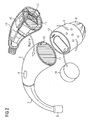
- FIG. 2 shows an exploded view of the hearing aid FIG. 1 , Shown again are the 3 housing parts 1, 2 and 3.
- the screw 4 between the first and second housing part is open.
- the battery compartment is visible, in which a substantially cylindrical battery 10 is used.
- electrical contacts 12 are located in the first housing part. When the first housing part is mounted on the second housing part, the electrical contacts 12 come to lie on the corresponding mating contacts 13 in the second housing part.
- the contacts 12 are used for electrical contacting of the electronic component 15 with the battery 10.
- further contacts may be provided to connect the selector 9 with the electronic component. When power is removed from the battery 10, this moisture can secrete. Therefore, the electronic component 15 is protected by a membrane 11 from moisture.
- the membrane 11 may be permeable to air and / or sound and / or water vapor.
- the electronic component 15 is located in a mounting frame 14. This has an outer shape which is complementary to the interior of the second housing part 2. Thus, the electronic component 15 can be mounted in the frame 14 in a simple manner in the housing part 2. For maintenance and repair purposes, an equally simple disassembly is possible.
- the waterproof membrane 11 is located on the mounting frame 14.
- the assembly of the electronic component 15 and the membrane 11 in one operation by inserting the mounting frame 14 in the second housing part 2.
- the mounting frame 14 At the top of the mounting frame, ie in the assembled state between The housing parts 2 and 3 is either a sound transducer to produce an acoustic stimulus for the user or an electrical connection to connect the transducer in the housing part 3b with the electronic component 15.
Landscapes
- Engineering & Computer Science (AREA)
- Acoustics & Sound (AREA)
- Neurosurgery (AREA)
- Otolaryngology (AREA)
- Physics & Mathematics (AREA)
- General Health & Medical Sciences (AREA)
- Health & Medical Sciences (AREA)
- Signal Processing (AREA)
- Manufacturing & Machinery (AREA)
- Battery Mounting, Suspending (AREA)
- Casings For Electric Apparatus (AREA)
- Headphones And Earphones (AREA)
- Adornments (AREA)
- Finger-Pressure Massage (AREA)
Description
- Die Erfindung betrifft ein Hörgerät mit einem dreiteiligen Gehäuse gemäß Anspruch 1.
- Aus der
DE 199 030 90 A1 ist ein Hörgerät der Eingangs beschriebenen Art bekannt. Um ein Eindringen von Feuchtigkeit in das Gehäuse weitgehend zu vermeiden, weist dieses vorbekannte Hörgerät keinerlei außenliegende Bedienelemente auf. Das Ein- und Ausschalten erfolgt vielmehr durch Demontage oder zumindest Lösen des ersten Gehäuseteiles mit der darin angeordneten Batterie. Eine Anpassung des Hörgerätes an verschiedene Umgebungsbedingungen, beispielsweise durch Änderung der Verstärkung, ist nicht vorgesehen. - Aus der
DE 195 02 994 A1 ist eine Batterieaufnahmekammer für eine Hörhilfe bekannt, welche mit einem Bajonettverschluss verschlossen werden kann. Dadurch kann die Batteriekammer in einfacher Weise wasserdicht verschlossen werden, wobei dies auch ungeschickten Personen möglich sein soll. - Aus der
DE 37 23 809 A1 ist ein hinter dem Ohr zu tragendes Hörgerät bekannt, das ein sichelförmiges Gehäuse umfasst, das an einem Ende einen Hörbügel und an dem anderen Ende ein Batteriefach aufweist. Dabei ist das Hörgerät mittels zweier Hörgeräteabschnitte so ausgestaltet, dass das Hörgerät verstellbar ist und an die Abmessungen des Ohres angepasst werden kann. - Aus der
EP 1 432 285 A3 ist eine hydrophobe Beschichtung von einzelnen Komponenten im Bereich von Spalten, Ritzen und Öffnungen eines Hörgeräts bekannt. - Aus der
WO 00/45617 - Ausgehend von diesem Stand der Technik liegt der Erfindung die Aufgabe zugrunde, ein Hörgerät anzugeben, welches eine Anpassung an unterschiedliche Betriebsbedingungen, d.h. unterschiedliche akustische Umgebungen, gestattet und gleichzeitig einen weitgehenden Schutz der empfindlichen verstellbar ist und an die Abmessungen des Ohres angepasst werden kann.
- Aus der
EP 1 432 285 A3 ist eine hydrophobe Beschichtung von einzelnen Komponenten im Bereich von Spalten, Ritzen und Öffnungen eines Hörgeräts bekannt. - Aus der
WO 00/45617 - Ausgehend von diesem Stand der Technik liegt der Erfindung die Aufgabe zugrunde, ein Hörgerät anzugeben, welches eine Anpassung an unterschiedliche Betriebsbedingungen, d.h. unterschiedliche akustische Umgebungen, gestattet und gleichzeitig einen weitgehenden Schutz der empfindlichen elektronischen Komponenten vor eindringender Feuchtigkeit bietet.
- Die Aufgabe wird erfindungsgemäß gelöst durch ein Hörgerät gemäß Anspruch 1.
- Das erfindungsgemäße Hörgerät weist einen ersten Gehäuseteil auf, welcher zusammen mit dem zweiten Gehäuseteil vom Benutzer hinter dem Ohr getragen wird. Im ersten Gehäuseteil ist dabei eine elektrische Energiequelle, beispielsweise ein Lithium-Polymer-Akkumulator, eine Zink-Luft-Batterie oder ein Kondensator eingebaut. Diese versorgt eine elektronische Komponente mit elektrischer Energie, welche sich im zweiten Gehäuseteil befindet.
- Eine elektronische Komponente im Sinne dieser Erfindung kann dabei eine elektronische Verstärkerschaltung sein, ein Geräuschgenerator, ein A/D- oder D/A-Wandler oder ein digitaler Signalprozessor. Diese Schaltungen können diskret oder integriert ausgeführt werden. Die genaue Funktion der elektronischen Komponente wird an die Bedürfnisse des Benutzers angepasst. Für wechselnde Einsatzbedingungen weist die elektronische Komponente mindestens zwei unterschiedliche Betriebszustände auf. Beispielsweise kann ein erster Betriebszustand mit einer ersten Verstärkung und ein zweiter Betriebszustand mit einer zweiten, höheren oder niedrigeren, Verstärkung vorgesehen sein. Jedoch ist es auch möglich, die Richtcharakteristik eines Empfängermikrofons umzuschalten oder eine Mehrzahl von Frequenzfiltern vorzusehen, welche vom Benutzer ausgewählt werden können.
- Zur Auswahl von mindestens zwei Betriebszuständen der elektronischen Komponente steht eine Auswahleinrichtung zur Verfügung, welche ein außenliegendes Bedienelement aufweist. Dieses Bedienelement kann im ersten Gehäuseteil oder im zweiten Gehäuseteil angeordnet sein. Im einfachsten Fall handelt es sich bei der Auswahleinrichtung um ein Potentiometer, welches die Verstärkung eines analogen Verstärkers steuert. Um ein Eindringen von Feuchtigkeit durch das Bedienelement zu verhindern, ist dieses flüssigkeitsdicht auf der Außenseite des Gehäuseteils angeordnet. Beispielsweise kann die Achse eines Potentiometers mit einer O-Ring-Dichtung versehen sein. Alternativ hierzu sind auch Schleifring-Dichtungen oder Labyrinth-Dichtungen möglich. Sofern es sich bei der Auswahleinrichtung um einen mechanischen Schalter handelt, kann dessen Bedienelement mittels eines Faltenbalges abgedichtet werden. Ein Druckschalter kann durch einen elastischen Gehäuseteil hindurch bedient werden. Somit wird die Wasserdichtigkeit des Hörgerätes durch das außenliegende Bedienelement nicht verschlechtert. Dennoch gewinnt der Benutzer an Bedienkomfort, indem er sein Gerät an unterschiedliche Betriebsbedingungen anpassen kann.
- Weiterhin weist das erfindungsgemäße Hörgerät ein drittes Gehäuseteil auf, welches einen akustischen Reiz in den Gehörgang des Benutzers leitet. Im einfachsten Fall kann dies ein einfacher Schlauch sein, welcher den Schall von einem im zweiten Gehäuseteil integrierten Schallwandler weiterleitet. In einer anderen Ausführungsform kann jedoch auch ein Schallwandler im Gehörgang des Benutzers vorgesehen sein, welcher über das dritte Gehäuseteil mit der elektronischen Komponente aus dem zweiten Gehäuseteil elektrisch verbunden wird. Schließlich können bei besonders großer Funktionsvielfalt neben dem Schallwandler auch weitere elektronische Komponenten im dritten Gehäuseteil angeordnet werden.
- Um ein Eindringen von Feuchtigkeit zu vermeiden, insbesondere bei sportlich aktiven Benutzern, ist in einer Ausführungsform der Erfindung vorgesehen, eine schalldurchlässige Membran an der Spitze des dritten Gehäuseteils anzuordnen. Als Spitze wird dabei dasjenige Ende des Gehäuseteils bezeichnet, welches dem Gehörgang am nächsten liegt. Eine solche Membran kann beispielsweise aus expandiertem Polytetrafluorethylen hergestellt werden. Diese ist für Schallwellen durchlässig, welche im zweiten oder dritten Gehäuseteil erzeugt werden. Ebenso ist die Membran für gasförmigen Wasserdampf durchlässig. Das Eindringen von flüssigem Wasser, Cerumen oder Schweiß wird jedoch zuverlässig verhindert. Somit bleibt auch das dritte Gehäuseteil innen sauber und trocken und die Haltbarkeit und die Betriebssicherheit des Hörgeräts wird erhöht.
- Beispielhaft kann das erfindungsgemäße Hörgerät als Tinitus-Masker lediglich Geräusche erzeugen oder aber als Verstärker Umgebungsgeräusche durch ein Mikrofon aufnehmen und durch einen Schallwandler wieder in den Gehörgang des Benutzers abgeben. Im letztgenannten Fall ist eine Mikrofonöffnung in einem oder mehreren Gehäuseteilen vorgesehen. Insbesondere ist eine Mikrofonöffnung im zweiten Gehäuseteil vorgesehen. Um weiterhin die Wasserdichtigkeit des Hörgerätes sicherzustellen, wird die Mikrofonöffnung ebenfalls mit einer wasserdichten Membran verschlossen.
- In Abhängigkeit des elektrischen Energiespeichers, welcher im ersten Gehäuseteil eingesetzt ist, kann es erforderlich sein, dass Luft in den ersten Gehäuseteil eindringen kann. Beispielsweise erfordert eine Zink-Luft-Batterie eine regelmäßige Luftzufuhr, um einen zuverlässigen Betrieb sicherzustellen. Um auch hier das Eindringen von Feuchtigkeit mit nachfolgender Beeinträchtigung der elektronischen Komponente zu vermeiden, sind diese Öffnungen in einem Ausführungsbeispiel ebenfalls mit einer teildurchlässigen Membran versehen, welche Luft eindringen lässt und gleichzeitig für flüssiges Wasser undurchdringlich ist. Bevorzugt befindet sich diese Membran dabei im Wesentlichen auf der durch die Begrenzungslinie der Öffnung definierten Fläche. Dadurch ist die Öffnung mit einer straff gespannten Membran verschlossen, ohne dass sackartige Ausbuchtungen der Membran vorhanden sind.
- Als Schutz vor Feuchtigkeit, die bei Betrieb des Energiespeichers entsteht oder als zusätzlicher Schutz der elektronischen Komponente, falls einmal unbeabsichtigt Wasser in den ersten Gehäuseteil eintritt, ist erfindungsgemäß an der Verbindungsfläche zwischen dem ersten und dem zweiten Gehäuseteil eine weitere wasserdichte Membran vorgesehen . Diese kann ebenfalls aus expandiertem Polytetrafluorethylen bestehen oder aber, wenn die Durchlässigkeit für Wasserdampf zweitrangig ist, aus einem beliebigen anderen Material.
- Um eine einfach Zugänglichkeit der elektronischen Komponenten, beispielsweise für Wartungsarbeiten, zu ermöglichen, sind diese in einer Ausführungsform auf einen Rahmen montiert. Die äußere Form dieses Rahmens ist dabei komplementär zur Innenform des zweiten Gehäuseteils. Dadurch kann nach Fertigstellung der elektronischen Komponenten und deren mechanischer Montage auf den Rahmen dieser als kompaktes Modul in den zweiten Gehäuseteil eingesetzt und dort gesichert werden. Besonders bevorzugt wird dabei an der dem ersten Gehäuseteil zugewandten Bodenfläche des Rahmens auch die wasserdichte Membran zur Abdichtung des zweiten Gehäuseteils angeordnet. Damit wird das Gehäuse ohne weitere Montagearbeit auch noch dicht verschlossen.
- Ohne Beschränkung des allgemeinen Erfindungsgedankens soll die Erfindung nachfolgend anhand von Figuren näher erläutert werden.
-
Figur 1 zeigt ein erfindungsgemäßes Hörgerät in zusammengebautem Zustand; -
Figur 2 zeigt eine Explosionszeichnung eines erfindungsgemäßen Hörgerätes. - Das Hörgerät nach
Figur 1 weist ein erstes Gehäuseteil 1, ein zweites Gehäuseteil 2 und ein drittes Gehäuseteil 3 auf. Zwischen dem ersten und dem zweiten Gehäuseteil befindet sich eine Verschraubung 4, welche mittels einer O-Ring-Dichtung flüssigkeitsdicht ausgeführt wird. Zwischen dem zweiten Gehäuseteil 2 und dem dritten Gehäuseteil 3a befindet sich ebenfalls eine Verschraubung 5, welche ebenfalls eine Dichtung aufweist. Statt der Verschraubungen 4 und 5 können auch Bajonett-Verschlüsse oder, bei elastischem Gehäusematerial, zusammensteckbare Verschlüsse ausgeführt werden. Die Gehäuseteile selbst bestehen aus einem Metall oder einer Legierung oder einem Kunststoff. Je nach Anforderungen an den Kunststoff kann es sich um ein Thermoplast oder ein Duroplast handeln. Der Kunststoff kann weich und anschmiegsam ausgeführt werden um den Tragekomfort zu erhöhen oder hart um so die elektronischen Komponenten im Inneren des Hörgerätes besser zu schützen. -
Figur 1 zeigt zwei verschiedene Ausführungen des dritten Gehäuseteils 3a und 3b. Gehäuseteil 3a enthält dabei selbst keine aktiven Komponenten. Der akustische Reiz wird durch die elektronischen Komponenten im Gehäuseteil 2 erzeugt und durch Gehäuseteil 3a in den Gehörgang des Benutzers geleitet. Um das Hörgerät für aktive Benutzer möglichst wasserdicht auszuführen und dabei die elektronischen Komponenten vor Schäden zu schützen, befindet sich an der Spitze 6 des Gehäuseteils 3a eine wasserdichte Membran 16. Diese verhindert das Eintreten zumindest von flüssigem Wasser in das Gehäuseteil 3a. Die Membran lässt im Gegenzug zumindest den Schall aus Gehäuseteil 3a austreten. Bevorzugt erlaubt die Membran 16 auch den Austritt von Wasserdampf aus dem Gehäuseteil 3a. - Das alternativ verwendbare Gehäuseteil 3b weist an seinem dem zweiten Gehäuseteil entferntem Ende einen Schallwandler 17 auf. Damit dieser ebenso wie die elektronischen Komponenten im Gehäuseteil 2 und 1 nicht durch Feuchtigkeit geschädigt werden, befindet sich auch an der Öffnung des Gehäuseteils 3b eine schalldurchlässige aber wasserdichte Membran 16. Der Schallwandler 17 wird durch innerhalb des Gehäuseteiles 3b laufende Anschlussleitungen an die elektronische Komponente im Gehäuseteil 2 angeschlossen. Da der erzeugte Schall nicht durch Resonanzen im Gehäuseteil 3a beeinträchtigt wird, ergibt sich bei Verwendung von Gehäuseteil 3b eine höhere Klangqualität.
- Das erfindungsgemäße Hörgerät nach
Figur 1 zeigt eine Auswahleinrichtung 9 zur Auswahl mehrerer Betriebszustände des Hörgeräts. Im einfachsten Fall kann die Auswahleinrichtung 9 ein Lautstärkesteller sein. Es ist jedoch auch möglich, das Hörgerät durch unterschiedliche Signalverarbeitungsprogramme an unterschiedliche Umgebungsgeräusche anzupassen. Zur Aufnahme von Umgebungsgeräuschen, welche dann weiterverarbeitet und verstärkt über die Spitze 6 bzw. den Schallwandler 17 abgegeben werden, befindet sich im Gehäuseteil 2 eine Mikrofonöffnung 8. Um die Wasserdichtigkeit nicht zu beeinträchtigen, ist auch diese Mikrofonöffnung durch eine schalldurchlässige und wasserdichte Membran verschlossen. - Im Ausführungsbeispiel nach
Figur 1 wird das Hörgerät durch eine Zink-Luft-Batterie betrieben. Diese benötigt ausreichenden Luftaustausch, um keine Kapazitätseinbußen zu zeigen. Hierfür sind Öffnungen 7 im Gehäuseteil 1 vorgesehen. Damit auch durch die Öffnungen 7 die Wasserdichtigkeit des Gehäuses nicht beeinträchtigt wird, werden diese mittels einer Membran verschlossen, welch für flüssiges Wasser undurchlässig ist. Ein Luftaustausch durch die Öffnungen 7 ist jedoch möglich. -
Figur 2 zeigt eine Explosionszeichnung des Hörgeräts nachFigur 1 . Dargestellt sind wieder die 3 Gehäuseteile 1, 2 und 3. Die Schraubverbindung 4 zwischen erstem und zweitem Gehäuseteil ist geöffnet. Im ersten Gehäuseteil 1 wird das Batteriefach sichtbar, in welches eine im Wesentlichen zylinderförmige Batterie 10 einsetzbar ist. Weiterhin befinden sich im ersten Gehäuseteil elektrische Kontakte 12. Bei Montage des ersten Gehäuseteils auf das zweite Gehäuseteil kommen die elektrischen Kontakte 12 auf den entsprechenden Gegenkontakten 13 im zweiten Gehäuseteil zu liegen. Die Kontakte 12 dienen der elektrischen Kontaktierung der elektronischen Komponente 15 mit der Batterie 10. Daneben können weitere Kontakte vorgesehen sein, um auch die Auswahleinrichtung 9 mit der elektronischen Komponente zu verbinden. Bei Stromentnahme aus der Batterie 10 kann diese Feuchtigkeit absondern. Daher ist die elektronische Komponente 15 durch eine Membran 11 vor Feuchtigkeit geschützt. Die Membran 11 kann für Luft und/oder Schall und/oder Wasserdampf durchlässig sein. - Zur Montageerleichterung befindet sich die elektronische Komponente 15 in einem Montagerahmen 14. Dieser weist eine äußere Form auf, welche zum Inneren des zweiten Gehäuseteils 2 komplementär ist. Somit kann die elektronische Komponente 15 im Rahmen 14 in einfacher Weise im Gehäuseteil 2 montiert werden. Zu Wartungs- und Reparaturzwecken ist eine ebenso einfache Demontage möglich. Bevorzugt befindet sich auch die wasserdichte Membran 11 auf dem Montagerahmen 14. Somit erfolgt die Montage der elektronischen Komponente 15 und der Membran 11 in einem Arbeitsgang durch Einschieben des Montagerahmens 14 in das zweite Gehäuseteil 2. An der Spitze des Montagerahmens, also in montiertem Zustand zwischen den Gehäuseteilen 2 und 3 befindet sich entweder ein Schallwandler, um einen akustischen Reiz für den Benutzer zu erzeugen oder aber ein elektrischer Anschluss, um den Schallwandler im Gehäuseteil 3b mit der elektronischen Komponente 15 zu verbinden.
Claims (13)
- Hörgerät mit einem ersten Gehäuseteil (1) zur Aufnahme einer elektrischen Energiequelle (10), einem zweiten Gehäuseteil (2) zur Aufnahme einer elektronischen Komponente (15) und einem dritten Gehäuseteil (3) zur Übermittlung eines akustischen Reizes in das Ohr eines Benutzers, bei welchem die Gehäuseteile eine lösbare, flüssigkeitsdichte Verbindung (4, 5) zueinander aufweisen und im zweiten oder ersten Gehäuseteil eine Auswahleinrichtung (9) zur Auswahl eines Betriebszustandes vorhanden ist, welche ein Bedienelement aufweist, welches flüssigkeitsdicht auf der Außenseite des Gehäuseteils angeordnet ist, dadurch gekennzeichnet, dass das zweite Gehäuseteil an seiner dem ersten Gehäuseteil zugewandten Öffnung mit einer wasserdichten Membran (11) versehen ist, die die Öffnung dicht verschließt.
- Hörgerät nach Anspruch 1, dadurch gekennzeichnet, dass das dritte Gehäuseteil an seinem der Verbindungsstelle mit dem zweiten Gehäuseteil gegenüberliegenden Ende (6) eine schalldurchlässige, wasserdichte Membran (16) aufweist.
- Hörgerät nach einem der Ansprüche 1 oder 2, dadurch gekennzeichnet, dass das zweite Gehäuseteil mindestens eine Öffnung (8) in seiner Außenwand aufweist, welche mit einer schalldurchlässigen, wasserdichten Membran versehen ist.
- Hörgerät nach einem der Ansprüche 1 bis 3, dadurch gekennzeichnet, dass das erste Gehäuseteil mindestens eine Öffnung (7) in seiner Außenwand aufweist, welche mit einer luftdurchlässigen, wasserdichten Membran versehen ist.
- Hörgerät nach Anspruch 4, dadurch gekennzeichnet, dass sich die Membran in der durch die Begrenzungslinie jeder Öffnung definierten Fläche befindet.
- Hörgerät nach einem der Ansprüche 1 bis 5, dadurch gekennzeichnet, dass die Membran Polytetrafluorethylen enthält.
- Hörgerät nach einem der Ansprüche 1 bis 6, dadurch gekennzeichnet, dass die flüssigkeitsdichten Verbindungen (4, 5) zwischen den Gehäuseteilen (1, 2, 3) eine Schraubverbindung umfassen.
- Hörgerät nach Anspruch 7, dadurch gekennzeichnet, dass die flüssigkeitsdichten Verbindungen zwischen den Gehäuseteilen mit einer O-Ring-Dichtung versehen sind.
- Hörgerät nach einem der Ansprüche 1 bis 8, dadurch gekennzeichnet, dass zwischen dem ersten und dem zweiten Gehäuseteil ein elektrischer Verbinder (12, 13) vorgesehen ist.
- Hörgerät nach Anspruch 9, dadurch gekennzeichnet, dass der elektrische Verbinder vier Kontakte aufweist.
- Hörgerät nach einem der Ansprüche 1 bis 10, dadurch gekennzeichnet, dass das dritte Gehäuseteil (3) einen Schallwandler (17) umfasst.
- Hörgerät nach einem der Ansprüche 1 bis 11, dadurch gekennzeichnet, dass die elektronische Komponente (15) von einem Rahmen (14) gehaltert ist, welcher zur Aufnahme in das zweite Gehäuseteil (2) vorgesehen ist.
- Hörgerät nach Anspruch 12, dadurch gekennzeichnet, dass der Rahmen (14) an seiner dem ersten Gehäuseteil (1) zugewandten Öffnung mit der wasserdichten Membran (11) versehen ist.
Applications Claiming Priority (1)
| Application Number | Priority Date | Filing Date | Title |
|---|---|---|---|
| DE102007047335A DE102007047335A1 (de) | 2007-10-04 | 2007-10-04 | Hörgerät |
Publications (2)
| Publication Number | Publication Date |
|---|---|
| EP2046074A1 EP2046074A1 (de) | 2009-04-08 |
| EP2046074B1 true EP2046074B1 (de) | 2012-02-22 |
Family
ID=40011352
Family Applications (1)
| Application Number | Title | Priority Date | Filing Date |
|---|---|---|---|
| EP08105239A Not-in-force EP2046074B1 (de) | 2007-10-04 | 2008-09-05 | Hörgerät |
Country Status (5)
| Country | Link |
|---|---|
| US (1) | US8103032B2 (de) |
| EP (1) | EP2046074B1 (de) |
| AT (1) | ATE546962T1 (de) |
| DE (1) | DE102007047335A1 (de) |
| DK (1) | DK2046074T3 (de) |
Families Citing this family (20)
| Publication number | Priority date | Publication date | Assignee | Title |
|---|---|---|---|---|
| US8457336B2 (en) * | 2004-02-05 | 2013-06-04 | Insound Medical, Inc. | Contamination resistant ports for hearing devices |
| DE102008051925B3 (de) * | 2008-10-16 | 2010-04-01 | Siemens Medical Instruments Pte. Ltd. | Hörvorrichtung mit Membran am Batteriefachinnenraum |
| DE102009015005B4 (de) * | 2009-03-26 | 2012-07-05 | Siemens Medical Instruments Pte. Ltd. | Elektronikvorrichtung zum Anschluss an eine Hörvorrichtungskomponente mit zweiteiliger Hülse und Hörvorrichtung |
| DE202010018103U1 (de) * | 2010-03-01 | 2014-03-06 | Audifon Gmbh & Co. Kg | Hörgerät |
| US9380396B2 (en) * | 2010-08-03 | 2016-06-28 | Sivantos Pte. Ltd. | Hearing instrument with an integral injection-molding casing |
| EP2416595B1 (de) * | 2010-08-03 | 2016-08-31 | Sivantos Pte. Ltd. | Hörinstrument mit einteiligem Spritzguss-Gehäuse |
| DE102011080609B4 (de) * | 2011-08-08 | 2016-10-27 | Sivantos Pte. Ltd. | Montage einer Signalverarbeitungskomponente in einem Gehäuse einer Hörvorrichtung |
| DE102010041263A1 (de) | 2010-09-23 | 2012-03-29 | Siemens Medical Instruments Pte. Ltd. | Hörgerätegehäuse mit Dichtungslippe |
| DE102010041656A1 (de) | 2010-09-29 | 2011-10-06 | Siemens Medical Instruments Pte. Ltd. | Mikrofonschutz für ein wasserdichtes Hörgerätegehäuse |
| US9974952B2 (en) | 2010-12-17 | 2018-05-22 | Advanced Bionics Ag | Sound processor housings, sound processors and implantable cochlear stimulation systems including the same |
| EP2652815A1 (de) | 2010-12-17 | 2013-10-23 | Advanced Bionics AG | Hörprozessorgehäuse, hörprozessoren und implantierbare cochleastimulationssysteme damit |
| EP2652814B1 (de) | 2010-12-17 | 2014-12-17 | Advanced Bionics AG | Hörprozessorgehäuse, hörprozessoren und implantierbare cochleastimulationssysteme damit |
| US8792664B2 (en) * | 2011-01-20 | 2014-07-29 | Cochlear Limited | Headworn sound processor case |
| DE102011083728A1 (de) | 2011-09-29 | 2013-04-04 | Siemens Medical Instruments Pte. Ltd. | Hörhilfegerät mit Dichtungsmitteln |
| US9930459B2 (en) * | 2014-07-24 | 2018-03-27 | Gn Hearing A/S | Hearing aid with detachable battery compartment |
| DE102015113694B4 (de) * | 2015-08-19 | 2021-09-09 | Preh Gmbh | Kapazitives Bedienelement mit verbesserter Störunanfälligkeit |
| US10284969B2 (en) | 2017-02-09 | 2019-05-07 | Starkey Laboratories, Inc. | Hearing device incorporating dynamic microphone attenuation during streaming |
| US11109168B2 (en) * | 2017-05-19 | 2021-08-31 | Cochlear Limited | External device of prosthesis connector |
| DE102022207352A1 (de) * | 2022-07-19 | 2024-01-25 | Sivantos Pte. Ltd. | Hörgerät |
| EP4456551A1 (de) * | 2023-04-24 | 2024-10-30 | GN Audio A/S | Hörgerät mit einer trennwand |
Family Cites Families (18)
| Publication number | Priority date | Publication date | Assignee | Title |
|---|---|---|---|---|
| DE3723809A1 (de) * | 1987-07-18 | 1989-01-26 | Bosch Gmbh Robert | Hinter dem ohr zu tragendes hoergeraet |
| DE8713369U1 (de) * | 1987-10-05 | 1989-02-09 | Siemens AG, 1000 Berlin und 8000 München | Vorrichtung zum Verschließen von Öffnungen an Hörgeräten oder Ohrpaßstücken für Hörgeräte |
| DE19502994C2 (de) * | 1994-01-31 | 1998-05-07 | Rion Co | Hörhilfe |
| US6041128A (en) * | 1994-01-31 | 2000-03-21 | Rion Kabushiki Kaisha | Battery receiving chamber and hearing aid |
| US6681022B1 (en) * | 1998-07-22 | 2004-01-20 | Gn Resound North Amerca Corporation | Two-way communication earpiece |
| CA2361270C (en) * | 1999-01-27 | 2009-04-07 | Auric Horsysteme Gmbh & Co. Kg | Hearing aid |
| DE19903090A1 (de) | 1999-01-27 | 2000-08-24 | Auric Hoersysteme Gmbh & Co Kg | Wasserdichtes Hör-Behandlungsgerät |
| AU4128199A (en) * | 1999-06-16 | 2001-01-09 | Phonak Ag | Hearing aid worn behind the ear and plug-in module for a hearing aid of this type |
| DE59915251D1 (de) * | 1999-06-16 | 2011-04-07 | Phonak Ag | Hinterohr-hörgerät |
| US7110562B1 (en) * | 2001-08-10 | 2006-09-19 | Hear-Wear Technologies, Llc | BTE/CIC auditory device and modular connector system therefor |
| US7139404B2 (en) * | 2001-08-10 | 2006-11-21 | Hear-Wear Technologies, Llc | BTE/CIC auditory device and modular connector system therefor |
| DE60325072D1 (de) * | 2002-09-10 | 2009-01-15 | Hear Wear Technologies Llc | Hinter-dem-ohr/vollständig-in-dem-ohr hörgerät und modulares verbindungssystem h |
| WO2004112431A1 (en) * | 2003-06-13 | 2004-12-23 | Oticon A/S | Electrical and mechanical connection between head worn communication device and accessory thereto |
| US7267847B2 (en) * | 2003-12-30 | 2007-09-11 | Phonak Ag | Hydrophobic coating of individual components of hearing aid devices |
| US20050249369A1 (en) * | 2004-05-05 | 2005-11-10 | Phonak Ag | Flexible frequency response shaping |
| US20050259839A1 (en) * | 2004-05-19 | 2005-11-24 | Phonak Ag | Construction for hearing devices or hearing aids |
| DK1480493T3 (da) * | 2004-05-19 | 2006-10-02 | Phonak Ag | Huskonstruktion til höreapparater eller hörehjælpemidler |
| DE102004051679B3 (de) * | 2004-10-22 | 2005-12-22 | Bess Pro Gmbh | Stimmprothese |
-
2007
- 2007-10-04 DE DE102007047335A patent/DE102007047335A1/de not_active Ceased
-
2008
- 2008-09-05 AT AT08105239T patent/ATE546962T1/de active
- 2008-09-05 EP EP08105239A patent/EP2046074B1/de not_active Not-in-force
- 2008-09-05 DK DK08105239.1T patent/DK2046074T3/da active
- 2008-10-01 US US12/286,675 patent/US8103032B2/en not_active Expired - Fee Related
Also Published As
| Publication number | Publication date |
|---|---|
| DE102007047335A1 (de) | 2009-04-09 |
| EP2046074A1 (de) | 2009-04-08 |
| US20090092270A1 (en) | 2009-04-09 |
| US8103032B2 (en) | 2012-01-24 |
| DK2046074T3 (da) | 2012-05-29 |
| ATE546962T1 (de) | 2012-03-15 |
Similar Documents
| Publication | Publication Date | Title |
|---|---|---|
| EP2046074B1 (de) | Hörgerät | |
| EP1915032B1 (de) | Hörhilfegerät | |
| EP3419311B1 (de) | Hörgerät | |
| DE60303561T2 (de) | Hörgerät mit Richtmikrofonen | |
| EP1484943B1 (de) | Hinterohr-Hörgerät | |
| DE102015208846B3 (de) | Hörgerät | |
| EP1183910A1 (de) | Hinterohr-hörgerät und aufsatzmodul für ein derartiges hörgerät | |
| EP0310866A1 (de) | Vorrichtung zum Verschliessen von Öffnungen an Hörgeräten oder Ohrpassstücken für Hörgeräte | |
| EP2680611B1 (de) | Hybrider Hörinstrument-Konnektor | |
| DE102008051925B3 (de) | Hörvorrichtung mit Membran am Batteriefachinnenraum | |
| EP1183907B1 (de) | Hinterohr-hörgerät | |
| DE102009056916A1 (de) | Hörgerät mit einer platzsparenden Anordnung von Mikrofonen und Schallöffnungen | |
| EP2200343A1 (de) | Im-Ohr-tragbares Hörhilfegerät mit einem Richtmikrofon | |
| CH694390A5 (de) | Am Kopf tragbares Hörgerät. | |
| EP1349425B1 (de) | Platzierung eines elektroakustischen Miniaturwandlers in einem Hörgerät | |
| DE102008055919A1 (de) | Vorrichtung zur Befestigung eines Hörers für Hörgeräte | |
| WO2017153020A1 (de) | Hörgerät mit rf-antenne | |
| EP2582157A1 (de) | Hörhilfegerät mit Dichtungsmitteln | |
| DE102012204287A1 (de) | Schaumstoffohrstück | |
| DE102007009748A1 (de) | Hörhilfegerät | |
| DE102009009174A1 (de) | Trocknungseinrichtung für eine Hörvorrichtung sowie passende Hörvorrichtung | |
| EP3439329B1 (de) | In-dem-ohr-hörgerät | |
| DE102006052436B4 (de) | Hörgerät | |
| DE102010009784B4 (de) | Hörgerät | |
| EP3188511A1 (de) | Hörgerät |
Legal Events
| Date | Code | Title | Description |
|---|---|---|---|
| PUAI | Public reference made under article 153(3) epc to a published international application that has entered the european phase |
Free format text: ORIGINAL CODE: 0009012 |
|
| AK | Designated contracting states |
Kind code of ref document: A1 Designated state(s): AT BE BG CH CY CZ DE DK EE ES FI FR GB GR HR HU IE IS IT LI LT LU LV MC MT NL NO PL PT RO SE SI SK TR |
|
| AX | Request for extension of the european patent |
Extension state: AL BA MK RS |
|
| 17P | Request for examination filed |
Effective date: 20090918 |
|
| 17Q | First examination report despatched |
Effective date: 20091016 |
|
| AKX | Designation fees paid |
Designated state(s): AT BE BG CH CY CZ DE DK EE ES FI FR GB GR HR HU IE IS IT LI LT LU LV MC MT NL NO PL PT RO SE SI SK TR |
|
| GRAP | Despatch of communication of intention to grant a patent |
Free format text: ORIGINAL CODE: EPIDOSNIGR1 |
|
| GRAS | Grant fee paid |
Free format text: ORIGINAL CODE: EPIDOSNIGR3 |
|
| GRAA | (expected) grant |
Free format text: ORIGINAL CODE: 0009210 |
|
| AK | Designated contracting states |
Kind code of ref document: B1 Designated state(s): AT BE BG CH CY CZ DE DK EE ES FI FR GB GR HR HU IE IS IT LI LT LU LV MC MT NL NO PL PT RO SE SI SK TR |
|
| REG | Reference to a national code |
Ref country code: GB Ref legal event code: FG4D Free format text: NOT ENGLISH |
|
| REG | Reference to a national code |
Ref country code: CH Ref legal event code: EP Ref country code: CH Ref legal event code: NV Representative=s name: SIEMENS SCHWEIZ AG |
|
| REG | Reference to a national code |
Ref country code: AT Ref legal event code: REF Ref document number: 546962 Country of ref document: AT Kind code of ref document: T Effective date: 20120315 |
|
| REG | Reference to a national code |
Ref country code: IE Ref legal event code: FG4D Free format text: LANGUAGE OF EP DOCUMENT: GERMAN |
|
| REG | Reference to a national code |
Ref country code: DE Ref legal event code: R096 Ref document number: 502008006461 Country of ref document: DE Effective date: 20120419 |
|
| REG | Reference to a national code |
Ref country code: DK Ref legal event code: T3 |
|
| REG | Reference to a national code |
Ref country code: NL Ref legal event code: VDEP Effective date: 20120222 |
|
| LTIE | Lt: invalidation of european patent or patent extension |
Effective date: 20120222 |
|
| PG25 | Lapsed in a contracting state [announced via postgrant information from national office to epo] |
Ref country code: IS Free format text: LAPSE BECAUSE OF FAILURE TO SUBMIT A TRANSLATION OF THE DESCRIPTION OR TO PAY THE FEE WITHIN THE PRESCRIBED TIME-LIMIT Effective date: 20120622 Ref country code: LT Free format text: LAPSE BECAUSE OF FAILURE TO SUBMIT A TRANSLATION OF THE DESCRIPTION OR TO PAY THE FEE WITHIN THE PRESCRIBED TIME-LIMIT Effective date: 20120222 Ref country code: HR Free format text: LAPSE BECAUSE OF FAILURE TO SUBMIT A TRANSLATION OF THE DESCRIPTION OR TO PAY THE FEE WITHIN THE PRESCRIBED TIME-LIMIT Effective date: 20120222 Ref country code: NO Free format text: LAPSE BECAUSE OF FAILURE TO SUBMIT A TRANSLATION OF THE DESCRIPTION OR TO PAY THE FEE WITHIN THE PRESCRIBED TIME-LIMIT Effective date: 20120522 Ref country code: NL Free format text: LAPSE BECAUSE OF FAILURE TO SUBMIT A TRANSLATION OF THE DESCRIPTION OR TO PAY THE FEE WITHIN THE PRESCRIBED TIME-LIMIT Effective date: 20120222 |
|
| PG25 | Lapsed in a contracting state [announced via postgrant information from national office to epo] |
Ref country code: FI Free format text: LAPSE BECAUSE OF FAILURE TO SUBMIT A TRANSLATION OF THE DESCRIPTION OR TO PAY THE FEE WITHIN THE PRESCRIBED TIME-LIMIT Effective date: 20120222 Ref country code: GR Free format text: LAPSE BECAUSE OF FAILURE TO SUBMIT A TRANSLATION OF THE DESCRIPTION OR TO PAY THE FEE WITHIN THE PRESCRIBED TIME-LIMIT Effective date: 20120523 Ref country code: LV Free format text: LAPSE BECAUSE OF FAILURE TO SUBMIT A TRANSLATION OF THE DESCRIPTION OR TO PAY THE FEE WITHIN THE PRESCRIBED TIME-LIMIT Effective date: 20120222 Ref country code: PT Free format text: LAPSE BECAUSE OF FAILURE TO SUBMIT A TRANSLATION OF THE DESCRIPTION OR TO PAY THE FEE WITHIN THE PRESCRIBED TIME-LIMIT Effective date: 20120622 |
|
| REG | Reference to a national code |
Ref country code: IE Ref legal event code: FD4D |
|
| PG25 | Lapsed in a contracting state [announced via postgrant information from national office to epo] |
Ref country code: CY Free format text: LAPSE BECAUSE OF FAILURE TO SUBMIT A TRANSLATION OF THE DESCRIPTION OR TO PAY THE FEE WITHIN THE PRESCRIBED TIME-LIMIT Effective date: 20120222 |
|
| PG25 | Lapsed in a contracting state [announced via postgrant information from national office to epo] |
Ref country code: CZ Free format text: LAPSE BECAUSE OF FAILURE TO SUBMIT A TRANSLATION OF THE DESCRIPTION OR TO PAY THE FEE WITHIN THE PRESCRIBED TIME-LIMIT Effective date: 20120222 Ref country code: EE Free format text: LAPSE BECAUSE OF FAILURE TO SUBMIT A TRANSLATION OF THE DESCRIPTION OR TO PAY THE FEE WITHIN THE PRESCRIBED TIME-LIMIT Effective date: 20120222 Ref country code: SI Free format text: LAPSE BECAUSE OF FAILURE TO SUBMIT A TRANSLATION OF THE DESCRIPTION OR TO PAY THE FEE WITHIN THE PRESCRIBED TIME-LIMIT Effective date: 20120222 Ref country code: SE Free format text: LAPSE BECAUSE OF FAILURE TO SUBMIT A TRANSLATION OF THE DESCRIPTION OR TO PAY THE FEE WITHIN THE PRESCRIBED TIME-LIMIT Effective date: 20120222 Ref country code: RO Free format text: LAPSE BECAUSE OF FAILURE TO SUBMIT A TRANSLATION OF THE DESCRIPTION OR TO PAY THE FEE WITHIN THE PRESCRIBED TIME-LIMIT Effective date: 20120222 Ref country code: IE Free format text: LAPSE BECAUSE OF FAILURE TO SUBMIT A TRANSLATION OF THE DESCRIPTION OR TO PAY THE FEE WITHIN THE PRESCRIBED TIME-LIMIT Effective date: 20120222 Ref country code: PL Free format text: LAPSE BECAUSE OF FAILURE TO SUBMIT A TRANSLATION OF THE DESCRIPTION OR TO PAY THE FEE WITHIN THE PRESCRIBED TIME-LIMIT Effective date: 20120222 |
|
| PGFP | Annual fee paid to national office [announced via postgrant information from national office to epo] |
Ref country code: GB Payment date: 20120917 Year of fee payment: 5 |
|
| PG25 | Lapsed in a contracting state [announced via postgrant information from national office to epo] |
Ref country code: SK Free format text: LAPSE BECAUSE OF FAILURE TO SUBMIT A TRANSLATION OF THE DESCRIPTION OR TO PAY THE FEE WITHIN THE PRESCRIBED TIME-LIMIT Effective date: 20120222 Ref country code: IT Free format text: LAPSE BECAUSE OF FAILURE TO SUBMIT A TRANSLATION OF THE DESCRIPTION OR TO PAY THE FEE WITHIN THE PRESCRIBED TIME-LIMIT Effective date: 20120222 |
|
| PLBE | No opposition filed within time limit |
Free format text: ORIGINAL CODE: 0009261 |
|
| STAA | Information on the status of an ep patent application or granted ep patent |
Free format text: STATUS: NO OPPOSITION FILED WITHIN TIME LIMIT |
|
| PGFP | Annual fee paid to national office [announced via postgrant information from national office to epo] |
Ref country code: FR Payment date: 20121002 Year of fee payment: 5 |
|
| 26N | No opposition filed |
Effective date: 20121123 |
|
| PGFP | Annual fee paid to national office [announced via postgrant information from national office to epo] |
Ref country code: DE Payment date: 20121119 Year of fee payment: 5 Ref country code: CH Payment date: 20121210 Year of fee payment: 5 |
|
| REG | Reference to a national code |
Ref country code: DE Ref legal event code: R097 Ref document number: 502008006461 Country of ref document: DE Effective date: 20121123 |
|
| BERE | Be: lapsed |
Owner name: SIEMENS MEDICAL INSTRUMENTS PTE. LTD. Effective date: 20120930 |
|
| PG25 | Lapsed in a contracting state [announced via postgrant information from national office to epo] |
Ref country code: ES Free format text: LAPSE BECAUSE OF FAILURE TO SUBMIT A TRANSLATION OF THE DESCRIPTION OR TO PAY THE FEE WITHIN THE PRESCRIBED TIME-LIMIT Effective date: 20120602 Ref country code: MC Free format text: LAPSE BECAUSE OF NON-PAYMENT OF DUE FEES Effective date: 20120930 |
|
| PG25 | Lapsed in a contracting state [announced via postgrant information from national office to epo] |
Ref country code: BG Free format text: LAPSE BECAUSE OF FAILURE TO SUBMIT A TRANSLATION OF THE DESCRIPTION OR TO PAY THE FEE WITHIN THE PRESCRIBED TIME-LIMIT Effective date: 20120522 Ref country code: BE Free format text: LAPSE BECAUSE OF NON-PAYMENT OF DUE FEES Effective date: 20120930 |
|
| PG25 | Lapsed in a contracting state [announced via postgrant information from national office to epo] |
Ref country code: MT Free format text: LAPSE BECAUSE OF FAILURE TO SUBMIT A TRANSLATION OF THE DESCRIPTION OR TO PAY THE FEE WITHIN THE PRESCRIBED TIME-LIMIT Effective date: 20120222 |
|
| PG25 | Lapsed in a contracting state [announced via postgrant information from national office to epo] |
Ref country code: TR Free format text: LAPSE BECAUSE OF FAILURE TO SUBMIT A TRANSLATION OF THE DESCRIPTION OR TO PAY THE FEE WITHIN THE PRESCRIBED TIME-LIMIT Effective date: 20120222 |
|
| REG | Reference to a national code |
Ref country code: CH Ref legal event code: PL |
|
| REG | Reference to a national code |
Ref country code: DK Ref legal event code: EBP Effective date: 20130930 |
|
| GBPC | Gb: european patent ceased through non-payment of renewal fee |
Effective date: 20130905 |
|
| PG25 | Lapsed in a contracting state [announced via postgrant information from national office to epo] |
Ref country code: LU Free format text: LAPSE BECAUSE OF NON-PAYMENT OF DUE FEES Effective date: 20120905 |
|
| REG | Reference to a national code |
Ref country code: DE Ref legal event code: R119 Ref document number: 502008006461 Country of ref document: DE Effective date: 20140401 |
|
| REG | Reference to a national code |
Ref country code: FR Ref legal event code: ST Effective date: 20140530 |
|
| PG25 | Lapsed in a contracting state [announced via postgrant information from national office to epo] |
Ref country code: LI Free format text: LAPSE BECAUSE OF NON-PAYMENT OF DUE FEES Effective date: 20130930 Ref country code: HU Free format text: LAPSE BECAUSE OF FAILURE TO SUBMIT A TRANSLATION OF THE DESCRIPTION OR TO PAY THE FEE WITHIN THE PRESCRIBED TIME-LIMIT Effective date: 20080905 Ref country code: CH Free format text: LAPSE BECAUSE OF NON-PAYMENT OF DUE FEES Effective date: 20130930 Ref country code: GB Free format text: LAPSE BECAUSE OF NON-PAYMENT OF DUE FEES Effective date: 20130905 |
|
| PG25 | Lapsed in a contracting state [announced via postgrant information from national office to epo] |
Ref country code: FR Free format text: LAPSE BECAUSE OF NON-PAYMENT OF DUE FEES Effective date: 20130930 Ref country code: DE Free format text: LAPSE BECAUSE OF NON-PAYMENT OF DUE FEES Effective date: 20140401 |
|
| PG25 | Lapsed in a contracting state [announced via postgrant information from national office to epo] |
Ref country code: DK Free format text: LAPSE BECAUSE OF NON-PAYMENT OF DUE FEES Effective date: 20130930 |
|
| REG | Reference to a national code |
Ref country code: AT Ref legal event code: MM01 Ref document number: 546962 Country of ref document: AT Kind code of ref document: T Effective date: 20130905 |
|
| PG25 | Lapsed in a contracting state [announced via postgrant information from national office to epo] |
Ref country code: AT Free format text: LAPSE BECAUSE OF NON-PAYMENT OF DUE FEES Effective date: 20130905 |