EP2046562B1 - Verfahren und system zur schichtweisen herstellung eines konkreten objekts - Google Patents
Verfahren und system zur schichtweisen herstellung eines konkreten objekts Download PDFInfo
- Publication number
- EP2046562B1 EP2046562B1 EP07747481A EP07747481A EP2046562B1 EP 2046562 B1 EP2046562 B1 EP 2046562B1 EP 07747481 A EP07747481 A EP 07747481A EP 07747481 A EP07747481 A EP 07747481A EP 2046562 B1 EP2046562 B1 EP 2046562B1
- Authority
- EP
- European Patent Office
- Prior art keywords
- layer
- liquid
- solidifying
- construction shape
- flexible layer
- Prior art date
- Legal status (The legal status is an assumption and is not a legal conclusion. Google has not performed a legal analysis and makes no representation as to the accuracy of the status listed.)
- Active
Links
Images



Classifications
-
- B—PERFORMING OPERATIONS; TRANSPORTING
- B29—WORKING OF PLASTICS; WORKING OF SUBSTANCES IN A PLASTIC STATE IN GENERAL
- B29C—SHAPING OR JOINING OF PLASTICS; SHAPING OF MATERIAL IN A PLASTIC STATE, NOT OTHERWISE PROVIDED FOR; AFTER-TREATMENT OF THE SHAPED PRODUCTS, e.g. REPAIRING
- B29C64/00—Additive manufacturing, i.e. manufacturing of three-dimensional [3D] objects by additive deposition, additive agglomeration or additive layering, e.g. by 3D printing, stereolithography or selective laser sintering
- B29C64/10—Processes of additive manufacturing
- B29C64/106—Processes of additive manufacturing using only liquids or viscous materials, e.g. depositing a continuous bead of viscous material
- B29C64/124—Processes of additive manufacturing using only liquids or viscous materials, e.g. depositing a continuous bead of viscous material using layers of liquid which are selectively solidified
- B29C64/129—Processes of additive manufacturing using only liquids or viscous materials, e.g. depositing a continuous bead of viscous material using layers of liquid which are selectively solidified characterised by the energy source therefor, e.g. by global irradiation combined with a mask
- B29C64/135—Processes of additive manufacturing using only liquids or viscous materials, e.g. depositing a continuous bead of viscous material using layers of liquid which are selectively solidified characterised by the energy source therefor, e.g. by global irradiation combined with a mask the energy source being concentrated, e.g. scanning lasers or focused light sources
-
- B—PERFORMING OPERATIONS; TRANSPORTING
- B29—WORKING OF PLASTICS; WORKING OF SUBSTANCES IN A PLASTIC STATE IN GENERAL
- B29C—SHAPING OR JOINING OF PLASTICS; SHAPING OF MATERIAL IN A PLASTIC STATE, NOT OTHERWISE PROVIDED FOR; AFTER-TREATMENT OF THE SHAPED PRODUCTS, e.g. REPAIRING
- B29C64/00—Additive manufacturing, i.e. manufacturing of three-dimensional [3D] objects by additive deposition, additive agglomeration or additive layering, e.g. by 3D printing, stereolithography or selective laser sintering
- B29C64/10—Processes of additive manufacturing
- B29C64/106—Processes of additive manufacturing using only liquids or viscous materials, e.g. depositing a continuous bead of viscous material
- B29C64/124—Processes of additive manufacturing using only liquids or viscous materials, e.g. depositing a continuous bead of viscous material using layers of liquid which are selectively solidified
-
- B—PERFORMING OPERATIONS; TRANSPORTING
- B33—ADDITIVE MANUFACTURING TECHNOLOGY
- B33Y—ADDITIVE MANUFACTURING, i.e. MANUFACTURING OF THREE-DIMENSIONAL [3D] OBJECTS BY ADDITIVE DEPOSITION, ADDITIVE AGGLOMERATION OR ADDITIVE LAYERING, e.g. BY 3D PRINTING, STEREOLITHOGRAPHY OR SELECTIVE LASER SINTERING
- B33Y10/00—Processes of additive manufacturing
Definitions
- the invention relates to a method for layerwise production of a tangible object according to the preamble of claim 1.
- the invention also relates to a system for layerwise production of a tangible object.
- the carrier plate together with the earlier solidified layers adhered thereon are moved upwards in order to separate the last formed solid layer from the separation layer of the bottom plate.
- the separated solid layer is moved to a predetermined position at a distance from the separation layer of the bottom plate for letting the liquid flow-in between the separated solid layer and the separation layer of the bottom plate.
- a drawback of the known method is, that during each method cycle the time required for said separation and for the liquid to flow-in between the separated solid layer and the separation layer of the bottom plate is relatively long. This restricts the speed of the production process.
- said solidifying and said separating are carried out such that solidifying of certain parts of the layer takes place simultaneously with separating of other, already solidified parts of the layer.
- the simultaneous solidifying and separating provides a speed gain of the process in itself. That is, the start of separating a layer does not have to wait until all parts of the layer have been solidified. Hence, there is little or no downtime of the separating means. Also, there is little or no downtime of the solidifying means.
- the separating of the layer is carried out more gradually in that it is performed part by part, instead of the whole layer at once.
- external forces to be exerted for the separation movement, and therefore the internal stresses in the tangible object do not need to be that high anymore for a given separation speed.
- such external forces can be increased relative to known methods, without violating a maximum permissible internal stress level in the tangible object. In this respect, a further gain in production speed can be obtained.
- FIG. 1-5 relates to a system according to claim 9 that can perform an example of a method according to claim 1.
- the same reference signs are used for similar or identical parts or aspects of the systems.
- each of the examples of Figs. 1-5 relates to a system for layerwise production of a tangible object, the system comprising:
- the tangible object is shown while being produced. It may for example be a prototype or model of an article of manufacture or other suitable type of object.
- the solidifying means can use any suitable chemical or physical process to solidify the predetermined area of the liquid layer.
- the solidifying means may for example initiate a chemical reaction of a component in the liquid which results in a solid reaction product.
- the liquid may be a liquid resin which can be cured by electro-magnetic radiation, for example a photo-polymer of which polymerisation can be activated by projecting light of a suitable wavelength.
- the liquid can be transformed into a solid by a suitable type of energy and the solidifying means may include a source of energy which can selectively provide the energy to the predetermined area.
- the source of energy may for example include a source of electro-magnetic radiation.
- the solidifying means may include a light source which can emit light which is projected onto the predetermined area of the liquid layer via a projection unit of the solidifying means in a pattern corresponding to the desired shape and size of the solid layer.
- the construction shape comprises a flexible layer having a liquid contacting side for being in contact with the liquid in the liquid reservoir, and the construction shape is arranged for bending, in operation, the flexible layer such that time-dependently varying contacting parts of the liquid contacting side of the flexible layer are in contact with the liquid layer for solidifying said certain parts of the layer, while time-dependently varying other parts of the liquid contacting side of the flexible layer have been separated from said other, already solidified parts of the layer.
- the construction shape comprises guiding means arranged for being in pressing contact with a side of the flexible layer opposite to the liquid contacting side for defining the time-dependently varying contacting parts of the liquid contacting side of the flexible layer.
- Such application of such guiding means is an easy and effective way of carrying out the bending of the flexible layer.
- the guiding means is arranged for realizing said pressing contact by means of sliding of the guiding means along said opposite side of the flexible layer.
- Such sliding contact allows for a large area of said pressing contact, which is for example favourable for keeping the time-dependently varying contacting parts of the liquid contacting side of the flexible layer flat in conditions when the liquid in the reservoir would exert relatively large pressure on these contacting parts.
- the guiding means is arranged for realizing said pressing contact by means of rolling of the guiding means along said opposite side of the flexible layer.
- said rolling of the guiding means is realized at least in that the flexible layer is rollable in a closed loop around at least two rollers.
- said rolling of the guiding means is realized at least by means of a winding and rewinding mechanism for the flexible layer.
- said simultaneous taking place of solidifying and of separating is realized in another way than in the examples shown in Figs. 1 , 2 and 3 . More in particular, for the embodiments of Figs. 4A, 4B , 5A and 5B , said simultaneous taking place of solidifying and of separating is realized in that a relative rotative movement is performed between the construction shape and the object under construction.
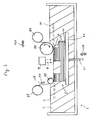
- FIG. 1 shows a system 1 according to the invention.
- the system 1 comprises a liquid reservoir 2 which, in the shown example, is filled with a liquid 3 upto a liquid level 4.
- the system 1 further comprises a construction shape 6 which is positioned below the liquid level 4 in the liquid reservoir 2.
- the reservoir 2 comprises a bottom platform 7 and the construction shape 6 comprises, located above platform 7, a flexible layer 8.
- the system 1 further comprises solidifying means 9 for solidifying a predetermined area of a layer 10 of the liquid 3, said liquid layer 10 adjoining the construction shape 6, so as to obtain a solid layer 14 of the tangible object 5, the solid layer thus having a predetermined shape.
- the solidifying means 9 is situated below the bottom platform 7. To enable the light or other radiation 15 of the solidifying means 9 to enter the liquid reservoir 2, the bottom platform 7 and the flexible layer 8 of the construction shape 6 are transparent to the radiation 15.
- system 1 further comprises separating means for separating said solid layer 14 from said construction shape 6.
- the system 1 further comprises moving means for moving, relative to one another, the separated solid layer 14 and the construction shape 6 to a predetermined position relative to one another for similar solidifying a predetermined area of a successive such liquid layer containing liquid 3 flown-inbetween the separated solid layer 14 and the construction shape 6, so as to obtain a successive such solid layer adhered to the solid layer 14.
- the moving means comprises a carrier plate 20 located above the construction shape 6.
- the carrier plate 20 is movable up and down relative to the construction shape 6 by the action of a carrier plate actuator 21.
- the carrier plate 20 can reach positions ranging from under the liquid level 4 to above it.
- a firstly formed solid layer 24 of the tangible object 5 is adhered to the underside of the carrier plate 20.
- Consecutively formed solid layers 34 are each adhered to a previously formed solid layer, respectively.
- the method for layerwise production of a tangible object is a cyclic method, wherein the described steps of solidifying, separating and positioning together are comprised in a single cycle of the method.
- the system is arranged for carrying out said solidifying and said separating such that solidifying of certain parts of the layer takes place simultaneously with separating of other, already solidified parts of the layer. This is explained as follows.
- the separating means for separating said layer 14 from said construction shape 6 simultaneously with the solidifying of a predetermined area of the layer 14 is explained as follows.
- the flexible layer 8 has a liquid contacting side for being in contact with the liquid 3.
- a guiding means 81 of the construction shape 6 Inbetween the flexible layer 8 on the one hand and the bottom platform 7 on the other hand, there is situated a guiding means 81 of the construction shape 6.
- Upper parts in Fig. 1 of the guiding means 81 are in pressing contact with a side of the flexible layer opposite to the liquid contacting side. In the shown example, said pressing contact is realized by means of sliding of the guiding means along said opposite side of the flexible layer.
- Lower parts in Fig. 1 of the guiding means 81 are in rolling contact with a side of the bottom platform 7 by means of rollers 80.
- the solidifying means 9 are in rolling contact with the platform 7 via similar such rollers 80. Both the guiding means 81 and the solidifying means 9 are synchronously movable relative to the platform 7 via these rollers 80 in either or both directions indicated by double arrow 73 in Fig. 1 .
- the platform 7 is transparent to the radiation 15, while the guiding means 81 contains a passageway for the radiation 15.
- the guiding means 81 can also be transparent to the radiation 15 instead of having a passageway therefor.
- FIG. 2 and 3 show examples of other embodiments of a system for layerwise production of a tangible object 5.
- FIG. 1 A difference with the embodiment of Fig. 1 is that for the embodiments of Figs. 2 and 3 an upper layer 14, instead of a lower layer 14, of an object 5 under production is solidified during each method cycle.
- the carrier plate 20 is situated under the object under production, instead of above it, while the solidifying means 9 is situated above the object under production, instead of under it.
- the carrier plate 20 is movable up and down in directions 125 by the action of an actuator 21 which extends through the bottom of the liquid reservoir 2 of the system. It is remarked that it is not essential that the actuator extends through a bottom of the liquid reservoir. Instead, different other types of actuators are possible, for example an actuator extending from the carrier plate in upwards direction until above the liquid level 4.
- a different guiding means is applied. That is, the guiding means in Figs. 2 and 3 comprises rollers 85 for realizing said pressing contact by means of rolling (instead of sliding) of the guiding means along said opposite side of the flexible layer 108.
- a difference between the examples of Figs. 2 and 3 is that for the example of Fig. 2 said rolling of the guiding means is realized at least in that the flexible layer 108 is rollable in a closed loop around at least two rollers 85, while for the example of Fig. 3 said rolling of the guiding means is realized at least by means of a winding and rewinding mechanism for the flexible layer 108.
- the winding and rewinding mechanism of Fig. 3 comprises two winding and rewinding rollers 88.
- the assembly comprising the flexible layer 108, the rollers and the solidifying means are synchronously movable relative to the reservoir 2 in either or both directions indicated by double arrow 173.
- the necessary driving means for such movement are not shown in the drawings.
- the flexible layer 108 is moving in one of the directions indicated by double arrow 174, such that the parts of the flexible layer 108 that are in contact with the layer 10 are not moving relative to the layer 10.
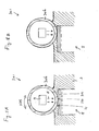
- FIGs. 4A and 4B show a fragment of a system 201 for layerwise production of a tangible object 5.
- the system 201 comprises: a construction shape 206 having a liquid contacting side 211 for being in contact with liquid 3 in a liquid reservoir of the system 201, as well as solidifying means 9 for emitting radiation 15.
- Reference numeral 214 denotes the last formed solid layer of the object 5.
- the construction shape 206 and the solid layer 214 have nonmatching shapes. In the embodiment shown in Figs. 4A and 4B said nonmatching shapes are realized in that the solid layer side 214 has a non-flat shape.
- Fig. 4B shows a condition during said rotative movement, in which condition the object 5 has an orientation relative to the construction shape 206, which orientation differs from that of Fig. 4A .
- different parts of the liquid 3 between the solid layer side 270 and the contacting side 211 are being solidified by exposing these parts to the radiation 15. In this way the solid layer 214 has been formed in the course of time.
- the application of the said nonmatching shapes results in improved separation, since the liquid 3 will quickly fill up the expanding interspace between the solid layer 214 and the construction shape 206.
- FIGs. 5A and 5B show a fragment of a system 301 for layerwise production of a tangible object 5.
- the system 301 comprises: a construction shape 306 having a liquid contacting side 311 for being in contact with liquid 3 in a liquid reservoir of the system 301, as well as solidifying means 9 for emitting radiation 15.
- Reference numeral 314 denotes the last formed solid layer of the object 5.
- the construction shape 306 and the solid layer 314 have nonmatching shapes. In the embodiment shown in Figs. 5A and 5B said nonmatching shapes are realized in that the liquid contacting side 311 has a non-flat shape.
- Fig. 5B shows a condition during said rotative movement, in which condition the object 5 has an orientation relative to the construction shape 306, which orientation differs from that of Fig. 5A .
- different parts of the liquid 3 between the solid layer side 370 and the contacting side 311 are being solidified by exposing these parts to the radiation 15. In this way the solid layer 314 has been formed in the course of time.
- the liquid reservoir may be higher or lower than shown in the fig.1 .
- the object may have any suitable size and shape.
- the invention is not limited to physical devices or units implemented in non-programmable hardware but can also be applied in programmable devices or units able to perform the desired device functions by operating in accordance with suitable program code.
- the devices may be physically distributed over a number of apparatuses, while functionally operating as a single device.
- devices functionally forming separate devices may be integrated in a single physical device.
- the specifications and drawings are, accordingly, to be regarded in an illustrative rather than in a restrictive sense.
- any reference signs placed between parentheses shall not be construed as limiting the claim.
- the word 'comprising' does not exclude the presence of other elements or steps than those listed in a claim.
- the words 'a' and 'an' shall not be construed as limited to 'only one', but instead are used to mean 'at least one', and do not exclude a plurality.
- the mere fact that certain measures are recited in mutually different claims does not indicate that a combination of these measures cannot be used to advantage.
Landscapes
- Physics & Mathematics (AREA)
- Optics & Photonics (AREA)
- Chemical & Material Sciences (AREA)
- Engineering & Computer Science (AREA)
- Materials Engineering (AREA)
- Mechanical Engineering (AREA)
- Manufacturing & Machinery (AREA)
- On-Site Construction Work That Accompanies The Preparation And Application Of Concrete (AREA)
- Revetment (AREA)
- Casting Or Compression Moulding Of Plastics Or The Like (AREA)
- Electrochromic Elements, Electrophoresis, Or Variable Reflection Or Absorption Elements (AREA)
- Toys (AREA)
- Consolidation Of Soil By Introduction Of Solidifying Substances Into Soil (AREA)
- Curing Cements, Concrete, And Artificial Stone (AREA)
Claims (15)
- Verfahren zur lagenweisen Herstellung eines konkreten Objekts (5), wobei das Verfahren umfasst:Bereitstellen eines Flüssigkeitsbehälters (2), der eine Flüssigkeit (3) enthält;Bereitstellen einer Konstruktionsform (6; 206; 306); undwiederholtes Durchführen von Verfahrenszyklen, wobei jeder Verfahrenszyklus die Schritte beinhaltet:- Verfestigen eines vorbestimmten Gebiets von einer Schicht (10) der Flüssigkeit (3), wenn die Flüssigkeitsschicht (10) an die Konstruktionsform angrenzt, um so eine feste Schicht (14; 214; 314) des konkreten Objekts (5) zu erhalten, wobei die feste Schicht dadurch eine vorbestimmte Form hat;- Trennen der festen Schicht von der Konstruktionsform; und- Bewegen der getrennten festen Schicht und der Konstruktionsform relativ zueinander in eine vorbestimmte Position relativ zueinander, um einen nachfolgenden solchen Verfahrenzyklus durchzuführen, um auf ähnliche Weise ein vorbestimmtes Gebiet von einer nachfolgenden solchen Flüssigkeitsschicht zu verfestigen, die Flüssigkeit (3) enthält, die zwischen die getrennte feste Schicht (14; 214; 314) und die Konstruktionsform (6; 206; 306) einströmt, um so eine nachfolgende solche feste Schicht zu erhalten, die an der festen Schicht anhaftet; dadurch gekennzeichnet, dassbei mindestens einem der Verfahrenszyklen das Verfestigen und das Trennen so durchgeführt werden, dass das Verfestigen bestimmter Teile der.Schicht (14; 214; 314) gleichzeitig mit dem Trennen von anderen, bereits verfestigten Teilen der Schicht stattfindet.
- Verfahren nach Anspruch 1, bei dem die Konstruktionsform eine flexible Schicht (8; 108) mit einer Flüssigkeitskontaktseite aufweist und bei dem das gleichzeitige Stattfinden des Verfestigens und des Trennens realisiert wird, indem die Flüssigkeitskontaktseite mit der Flüssigkeit (3) in dem Flüssigkeitsbehälter (2) in Kontakt gebracht und die flexible Schicht so gebogen wird, dass zeitabhängig variierende Kontaktteile der Flüssigkeitskontaktseite der flexiblen Schicht (8; 108) mit der Flüssigkeitsschicht (10) in Kontakt gebracht werden, um die bestimmten Teile der Schicht (10) zu verfestigen, während zeitabhängig variierende andere Teile der Flüssigkeitskontaktseite der flexiblen Schicht (8; 108) von den anderen, bereits verfestigten Teilen der Schicht (10) getrennt werden.
- Verfahren nach Anspruch 2, bei dem die Konstruktionsform (6) eine Führungseinrichtung (81; 85; 87) aufweist und bei dem die Führungseinrichtung in Druckkontakt mit der Seite der flexiblen Schicht (8; 108) gebracht wird, die der Flüssigkeitskontaktseite gegenüberliegt, um die zeitabhängig variierenden Kontaktteile der Flüssigkeitskontaktseite der flexiblen Schicht zu definieren.
- Verfahren nach Anspruch 3, bei dem der Druckkontakt durch Verschieben der Führungseinrichtung (81) entlang der gegenüberliegenden Seite der flexiblen Schicht (8) realisiert wird.
- Verfahren nach Anspruch 3, bei dem der Druckkontakt durch Rollen der Führungseinrichtung (85; 87) entlang der gegenüberliegenden Seite der flexiblen Schicht (108) realisiert wird.
- Verfahren nach Anspruch 5, bei dem das Rollen der Führungseinrichtung (85) mindestens realisiert wird, indem die flexible Schicht (108) in einer geschlossenen Schleife um mindestens zwei Rollen (85) gerollt wird.
- Verfahren nach Anspruch 5, bei dem das Rollen der Führungseinrichtung (87) mindestens realisiert wird, indem die flexible Schicht (108) mittels eines Aufwickel-und Abwickelmechanismus (88) aufgewickelt und abgewickelt wird.
- Verfahren nach Anspruch 1, bei dem das gleichzeitige Stattfinden des Verfestigens und des Trennens realisiert wird, indem eine relative Rotationsbewegung zwischen der Konstruktionsform (206; 306) und dem sich in Konstruktion befindlichen Objekt (5) durchgeführt wird.
- System zur lagenweisen Herstellung eines konkreten Objekts (5), wobei das System aufweist:einen Flüssigkeitsbehälter (2), der darin eine Flüssigkeit (3) enthält;eine Konstruktionsform (6; 206; 306), um mit der Flüssigkeit in dem Flüssigkeitsbehälter Kontakt zu haben;eine Verfestigungseinrichtung (9), um ein vorbestimmtes Gebiet von einer Schicht (10) der Flüssigkeit (3) zu verfestigen, wobei die Flüssigkeitsschicht (10) an die Konstruktionsform angrenzt, um so eine feste Schicht (14; 214; 314) des konkreten Objekts (5) zu erhalten, wobei die feste Schicht dadurch eine vorbestimmte Form hat;eine Trenneinrichtung (8, 80, 81; 108, 85; 108, 87; 275; 375), um die feste Schicht von der Konstruktionsform zu trennen;eine Bewegungseinrichtung (21), um die getrennte feste Schicht und die Konstruktionsform relativ zueinander in eine vorbestimmte Position relativ zueinander zu bewegen, um auf ähnliche Weise ein vorbestimmtes Gebiet von einer nachfolgenden solchen Flüssigkeitsschicht zu verfestigen, die Flüssigkeit (3) enthält, die zwischen die getrennte feste Schicht (14; 214; 314) und die Konstruktionsform (6; 206; 306) einströmt, um so eine nachfolgende solche feste Schicht zu erhalten, die an der festen Schicht anhaftet;
dadurch gekennzeichnet, dassdas System ausgestaltet ist, um das Verfestigen und das Trennen so durchzuführen, dass das Verfestigen bestimmter Teile der Schicht (14; 214; 314) gleichzeitig mit dem Trennen von anderen, bereits verfestigten Teilen der Schicht stattfindet. - System nach Anspruch 9, bei dem die Konstruktionsform eine flexible Schicht (8; 108) mit einer Flüssigkeitskontaktseite aufweist, um mit der Flüssigkeit (3) in dem Flüssigkeitsbehälter (2) Kontakt zu haben, und wobei die Konstruktionsform (6) ausgestaltet ist, um bei Betrieb die flexible Schicht so zu biegen, dass zeitabhängig variierende Kontaktteile der Flüssigkeitskontaktseite der flexiblen Schicht (8; 108) mit der Flüssigkeitsschicht (10) Kontakt haben, um die bestimmten Teile der Schicht (10) zu verfestigen, während zeitabhängig variierende andere Teile der Flüssigkeitskontaktseite der flexiblen Schicht (8; 108) von den anderen, bereits verfestigten Teilen der Schicht (10) getrennt werden.
- System nach Anspruch 10, bei dem die Konstruktionsform (6) eine Führungseinrichtung (81; 85; 87) aufweist, die ausgestaltet ist, um mit einer Seite der flexiblen Schicht (8; 108), die der Flüssigkeitskontaktseite gegenüberliegt, Druckkontakt zu haben, um die zeitabhängig variierenden Kontaktteile der Flüssigkeitskontaktseite der flexiblen Schicht zu definieren.
- System nach Anspruch 11, bei dem die Führungseinrichtung ausgestaltet ist, um den Druckkontakt durch Verschieben der Führungseinrichtung (81) entlang der gegenüberliegenden Seite der flexiblen Schicht (8) zu realisieren.
- System nach Anspruch 11, bei dem die Führungseinrichtung ausgestaltet ist, um den Druckkontakt durch Rollen der Führungseinrichtung (85; 87) entlang der gegenüberliegenden Seite der flexiblen Schicht (108) zu realisieren.
- System nach Anspruch 13, bei dem das Rollen der Führungseinrichtung (85) mindestens realisiert wird, indem die flexible Schicht (108) in einer geschlossenen Schleife um mindestens zwei Rollen (85) rollbar ist.
- System nach Anspruch 13, bei dem das Rollen der Führungseinrichtung (87) mindestens mit Hilfe eines Aufwickel-und Abwickelmechanismus (88) für die flexible Schicht (108) realisiert wird.
Priority Applications (1)
| Application Number | Priority Date | Filing Date | Title |
|---|---|---|---|
| EP07747481A EP2046562B1 (de) | 2006-07-18 | 2007-06-01 | Verfahren und system zur schichtweisen herstellung eines konkreten objekts |
Applications Claiming Priority (3)
| Application Number | Priority Date | Filing Date | Title |
|---|---|---|---|
| EP06076434A EP1880832A1 (de) | 2006-07-18 | 2006-07-18 | Verfahren und System zur schichtweisen Herstellung eines greifbaren Gegenstandes |
| PCT/NL2007/050258 WO2008010708A1 (en) | 2006-07-18 | 2007-06-01 | Method and system for layerwise production of a tangible object |
| EP07747481A EP2046562B1 (de) | 2006-07-18 | 2007-06-01 | Verfahren und system zur schichtweisen herstellung eines konkreten objekts |
Publications (2)
| Publication Number | Publication Date |
|---|---|
| EP2046562A1 EP2046562A1 (de) | 2009-04-15 |
| EP2046562B1 true EP2046562B1 (de) | 2010-10-06 |
Family
ID=37497883
Family Applications (3)
| Application Number | Title | Priority Date | Filing Date |
|---|---|---|---|
| EP06076434A Withdrawn EP1880832A1 (de) | 2006-07-18 | 2006-07-18 | Verfahren und System zur schichtweisen Herstellung eines greifbaren Gegenstandes |
| EP07747481A Active EP2046562B1 (de) | 2006-07-18 | 2007-06-01 | Verfahren und system zur schichtweisen herstellung eines konkreten objekts |
| EP07793859A Not-in-force EP2043847B1 (de) | 2006-07-18 | 2007-07-18 | Verfahren und system zur lagenweisen herstellung eines konkreten objekts |
Family Applications Before (1)
| Application Number | Title | Priority Date | Filing Date |
|---|---|---|---|
| EP06076434A Withdrawn EP1880832A1 (de) | 2006-07-18 | 2006-07-18 | Verfahren und System zur schichtweisen Herstellung eines greifbaren Gegenstandes |
Family Applications After (1)
| Application Number | Title | Priority Date | Filing Date |
|---|---|---|---|
| EP07793859A Not-in-force EP2043847B1 (de) | 2006-07-18 | 2007-07-18 | Verfahren und system zur lagenweisen herstellung eines konkreten objekts |
Country Status (9)
| Country | Link |
|---|---|
| US (3) | US20100227068A1 (de) |
| EP (3) | EP1880832A1 (de) |
| JP (2) | JP4837098B2 (de) |
| CN (2) | CN101495295B (de) |
| AT (2) | ATE483576T1 (de) |
| CA (2) | CA2657671C (de) |
| DE (2) | DE602007009687D1 (de) |
| ES (2) | ES2354125T3 (de) |
| WO (2) | WO2008010708A1 (de) |
Cited By (1)
| Publication number | Priority date | Publication date | Assignee | Title |
|---|---|---|---|---|
| WO2023107975A1 (en) * | 2021-12-09 | 2023-06-15 | Formlabs Inc. | Blade assist part peel for additive manufacturing |
Families Citing this family (56)
| Publication number | Priority date | Publication date | Assignee | Title |
|---|---|---|---|---|
| EP1876012A1 (de) | 2006-07-07 | 2008-01-09 | Nederlandse Organisatie voor Toegepast-Natuuurwetenschappelijk Onderzoek TNO | Verfahren und System zur schichtweisen Herstellung eines greifbaren Gegenstandes |
| EP1880832A1 (de) * | 2006-07-18 | 2008-01-23 | Nederlandse Organisatie voor Toegepast-Natuuurwetenschappelijk Onderzoek TNO | Verfahren und System zur schichtweisen Herstellung eines greifbaren Gegenstandes |
| US8678805B2 (en) | 2008-12-22 | 2014-03-25 | Dsm Ip Assets Bv | System and method for layerwise production of a tangible object |
| US8777602B2 (en) | 2008-12-22 | 2014-07-15 | Nederlandse Organisatie Voor Tobgepast-Natuurwetenschappelijk Onderzoek TNO | Method and apparatus for layerwise production of a 3D object |
| EP2379310B1 (de) | 2008-12-22 | 2018-11-28 | Nederlandse Organisatie voor toegepast- natuurwetenschappelijk onderzoek TNO | Verfahren und vorrichtung zur schichtweisen herstellung eines dreidimensionalen objektes |
| US10293947B2 (en) * | 2010-05-27 | 2019-05-21 | Goodrich Corporation | Aircraft heating system |
| JP5774825B2 (ja) | 2010-08-19 | 2015-09-09 | ソニー株式会社 | 3次元造形装置及び造形物の製造方法 |
| CN102529096B (zh) * | 2010-12-20 | 2015-10-14 | 卡尔·赫尔 | 用于制造三维的物品的装置 |
| ES2681980T3 (es) * | 2011-06-28 | 2018-09-17 | Global Filtration Systems, A Dba Of Gulf Filtration Systems Inc. | Aparato para formar objetos tridimensionales utilizando solidificación lineal |
| WO2013177620A1 (en) * | 2012-05-29 | 2013-12-05 | Zydex Pty Ltd | Device for making an object and a method for making an object |
| ITVI20120183A1 (it) * | 2012-07-27 | 2014-01-28 | Dws Srl | Cartuccia per macchina stereolitografica, macchina stereolitografica comprendente tale cartuccia e metodo di produzione di tale cartuccia |
| JP6456353B2 (ja) * | 2013-03-12 | 2019-01-23 | オレンジ・メーカー・エルエルシー | 渦巻状の積上げを使用した3d印刷 |
| GB2514139A (en) * | 2013-05-14 | 2014-11-19 | Aghababaie Lin & Co Ltd | Apparatus for fabrication of three dimensional objects |
| AT514493B1 (de) * | 2013-06-17 | 2015-04-15 | Way To Production Gmbh | Anlage zum schichtweisen Aufbau eines Körpers und Wanne hiefür |
| US9452567B2 (en) * | 2013-08-27 | 2016-09-27 | Kao-Chih Syao | Stereolithography apparatus |
| US10114289B2 (en) | 2014-04-15 | 2018-10-30 | Nederlandse Organisatie Voor Toegepast-Natuurwetenschappelijk Onderzoek Tno | Exposure head, exposure apparatus and method of operating an exposure head |
| BR112016029753A2 (pt) * | 2014-06-20 | 2017-08-22 | Carbon Inc | impressão tridimensional com alimentação recíproca de líquidos polimerizáveis |
| US10166725B2 (en) | 2014-09-08 | 2019-01-01 | Holo, Inc. | Three dimensional printing adhesion reduction using photoinhibition |
| TWI568601B (zh) * | 2014-10-02 | 2017-02-01 | 三緯國際立體列印科技股份有限公司 | 立體列印裝置及其列印方法 |
| US20160167301A1 (en) * | 2014-12-12 | 2016-06-16 | Autodesk, Inc. | Polymeric photoinitiators for 3d printing applications |
| US10118343B1 (en) * | 2014-12-19 | 2018-11-06 | X Development Llc | Fabrication baseplate with anchor channels |
| US9914292B2 (en) * | 2015-04-02 | 2018-03-13 | Massivit 3D Printing Technologies Ltd | Additive manufacturing device |
| JP5928631B2 (ja) * | 2015-04-02 | 2016-06-01 | ソニー株式会社 | 3次元造形装置及び3次元造形方法 |
| JP6020672B2 (ja) * | 2015-07-02 | 2016-11-02 | ソニー株式会社 | 3次元造形装置及び造形物の製造方法 |
| CN105082541B (zh) * | 2015-08-07 | 2017-06-13 | 京东方科技集团股份有限公司 | 一种3d打印机及3d打印系统 |
| US10384439B2 (en) * | 2015-11-06 | 2019-08-20 | Stratasys, Inc. | Continuous liquid interface production system with viscosity pump |
| PL3374163T3 (pl) * | 2015-11-13 | 2023-04-24 | Paxis Llc | Urządzenie, układ i sposób wytwarzania przyrostowego |
| US10717263B2 (en) | 2015-11-13 | 2020-07-21 | Paxis Llc | Additive manufacturing apparatus, system, and method |
| US11141919B2 (en) | 2015-12-09 | 2021-10-12 | Holo, Inc. | Multi-material stereolithographic three dimensional printing |
| AT518465B1 (de) * | 2016-03-25 | 2017-11-15 | Stadlmann Klaus | Anlage und Verfahren zum Generieren eines dreidimensionalen Körpers |
| AT518051B1 (de) * | 2016-04-19 | 2017-07-15 | Klaus Stadlmann Dr | Vorrichtung und Verfahren zur Steigerung der Anhaftung einer Bauteilschicht an einem Trägerobjekt |
| US11707884B2 (en) * | 2016-07-14 | 2023-07-25 | University Of Southern California | Sliding window screen for reducing resin refilling time in stereolithography |
| KR102233625B1 (ko) * | 2016-08-23 | 2021-03-31 | 캐논 가부시끼가이샤 | 3차원 조형 장치 및 3차원 조형물의 제조 방법 |
| JP6344447B2 (ja) * | 2016-10-05 | 2018-06-20 | ソニー株式会社 | 3次元造形装置及び造形物の製造方法 |
| JP6844217B2 (ja) * | 2016-11-24 | 2021-03-17 | ソニー株式会社 | 情報処理装置、造形装置、情報処理方法、およびプログラム |
| WO2018148632A1 (en) * | 2017-02-13 | 2018-08-16 | Carbon, Inc. | Method of making composite objects by additive manufacturing |
| US10935891B2 (en) | 2017-03-13 | 2021-03-02 | Holo, Inc. | Multi wavelength stereolithography hardware configurations |
| GB2564956B (en) | 2017-05-15 | 2020-04-29 | Holo Inc | Viscous film three-dimensional printing systems and methods |
| CN107031036B (zh) * | 2017-06-06 | 2022-03-11 | 清锋(北京)科技有限公司 | 三维打印装置及三维打印方法 |
| US10245785B2 (en) | 2017-06-16 | 2019-04-02 | Holo, Inc. | Methods for stereolithography three-dimensional printing |
| EP3661730A4 (de) * | 2017-08-03 | 2021-04-07 | Effusiontech Pty Ltd | Verfahren zum 3d-drucken |
| JP2021500250A (ja) * | 2017-10-20 | 2021-01-07 | フォームラブス, インコーポレーテッドFormlabs, Inc. | 積層造形において光を適用するための技術、関連するシステムおよび方法 |
| JP7289304B2 (ja) * | 2017-12-31 | 2023-06-09 | ストラタシス リミテッド | 予め規定された表面品質を得るための3d印刷 |
| CA3096390C (en) * | 2018-04-06 | 2023-10-17 | Paxis Llc | Additive manufacturing apparatus, system, and method |
| CN110896616B (zh) * | 2018-05-05 | 2022-07-29 | 清锋(北京)科技有限公司 | 阻粘元件、三维打印装置及三维打印方法 |
| JP2018140643A (ja) * | 2018-05-22 | 2018-09-13 | ソニー株式会社 | 3次元造形装置及び造形物の製造方法 |
| US11167491B2 (en) * | 2018-06-01 | 2021-11-09 | Formlabs, Inc. | Multi-film containers for additive fabrication and related systems and methods |
| CN110576609A (zh) * | 2018-06-07 | 2019-12-17 | 三纬国际立体列印科技股份有限公司 | 立体打印装置及其成型水槽 |
| CN117067579A (zh) | 2018-12-26 | 2023-11-17 | 霍洛公司 | 用于三维打印系统和方法的传感器 |
| EP3842864B1 (de) * | 2019-12-23 | 2022-08-03 | Cubicure GmbH | Systeme und verfahren zur lithographiebasierten generativen fertigung von dreidimensionalen (3d) strukturen |
| US12358222B2 (en) | 2020-08-14 | 2025-07-15 | Paxis Llc | Additive manufacturing apparatus, system, and method |
| JP2024506343A (ja) * | 2021-02-10 | 2024-02-13 | オーピーティー インダストリーズ,インコーポレイテッド | 柔軟な基材上の積層造形 |
| EP4326531A4 (de) | 2021-04-19 | 2025-05-28 | Holo, Inc. | Systeme und verfahren für stereolithografisches dreidimensionales drucken |
| US20250001676A1 (en) * | 2023-06-29 | 2025-01-02 | 3D Systems, Inc. | Stereolithography Apparatus for Improving Planarity of a Transparent Sheet |
| WO2026043880A1 (en) * | 2024-08-20 | 2026-02-26 | Bmf Precision, Inc. | Surface separation in resin 3d printing by gasket deformation |
| WO2026064236A1 (en) * | 2024-09-17 | 2026-03-26 | Bmf Precision, Inc. | Surface Separation in Resin 3D Printing by Suction Deformation |
Family Cites Families (15)
| Publication number | Priority date | Publication date | Assignee | Title |
|---|---|---|---|---|
| US5164128A (en) * | 1988-04-18 | 1992-11-17 | 3D Systems, Inc. | Methods for curing partially polymerized parts |
| US5876550A (en) * | 1988-10-05 | 1999-03-02 | Helisys, Inc. | Laminated object manufacturing apparatus and method |
| JPH03244528A (ja) * | 1989-09-28 | 1991-10-31 | Three D Syst Inc | 実質的に平担な立体平版加工面の形成装置および方法 |
| US5009585A (en) * | 1989-12-18 | 1991-04-23 | Mitsui Engineering & Shipbuilding Co., Ltd. | Optical molding apparatus and movable base device therefor |
| US5143817A (en) * | 1989-12-22 | 1992-09-01 | E. I. Du Pont De Nemours And Company | Solid imaging system |
| CA2045275A1 (en) * | 1990-06-26 | 1991-12-27 | John A. Lawton | Solid imaging system using incremental photoforming |
| US5122441A (en) * | 1990-10-29 | 1992-06-16 | E. I. Du Pont De Nemours And Company | Method for fabricating an integral three-dimensional object from layers of a photoformable composition |
| DE4125534A1 (de) * | 1991-08-01 | 1993-02-18 | Eos Electro Optical Syst | Verfahren und vorrichtung zum herstellen eines objekts mittels stereograhpie |
| JPH0784033B2 (ja) * | 1992-02-20 | 1995-09-13 | 帝人製機株式会社 | 光造形装置および光造形方法 |
| JP3803735B2 (ja) * | 1996-02-14 | 2006-08-02 | 独立行政法人理化学研究所 | リコートと同時に光走査する光固化造形装置 |
| WO1999059812A1 (en) * | 1998-05-20 | 1999-11-25 | Helisys, Inc. | Apparatus and method for manufacturing three-dimensional objects |
| DE19957370C2 (de) * | 1999-11-29 | 2002-03-07 | Carl Johannes Fruth | Verfahren und Vorrichtung zum Beschichten eines Substrates |
| DE10204985B4 (de) * | 2002-02-07 | 2006-09-07 | BECKMANN-INSTITUT für Technologieentwicklung e.V. | Verfahren und Vorrichtung zum Herstellen eines dreidimensionalen Objektes |
| DE10256672B4 (de) * | 2002-12-04 | 2019-05-09 | Envisiontec Gmbh | Verfahren zur Trennung stereolithographisch ausgehärteter Materialschichten von einer Kontaktfläche |
| EP1880832A1 (de) * | 2006-07-18 | 2008-01-23 | Nederlandse Organisatie voor Toegepast-Natuuurwetenschappelijk Onderzoek TNO | Verfahren und System zur schichtweisen Herstellung eines greifbaren Gegenstandes |
-
2006
- 2006-07-18 EP EP06076434A patent/EP1880832A1/de not_active Withdrawn
-
2007
- 2007-06-01 CN CN2007800273312A patent/CN101495295B/zh active Active
- 2007-06-01 EP EP07747481A patent/EP2046562B1/de active Active
- 2007-06-01 CA CA2657671A patent/CA2657671C/en active Active
- 2007-06-01 DE DE602007009687T patent/DE602007009687D1/de active Active
- 2007-06-01 WO PCT/NL2007/050258 patent/WO2008010708A1/en not_active Ceased
- 2007-06-01 US US12/374,165 patent/US20100227068A1/en not_active Abandoned
- 2007-06-01 AT AT07747481T patent/ATE483576T1/de not_active IP Right Cessation
- 2007-06-01 ES ES07747481T patent/ES2354125T3/es active Active
- 2007-06-01 JP JP2009520692A patent/JP4837098B2/ja active Active
- 2007-07-18 AT AT07793859T patent/ATE483575T1/de not_active IP Right Cessation
- 2007-07-18 JP JP2009520694A patent/JP4833338B2/ja not_active Expired - Fee Related
- 2007-07-18 CN CN2007800270988A patent/CN101489766B/zh not_active Expired - Fee Related
- 2007-07-18 CA CA2657678A patent/CA2657678C/en not_active Expired - Fee Related
- 2007-07-18 WO PCT/NL2007/050358 patent/WO2008010715A1/en not_active Ceased
- 2007-07-18 DE DE602007009684T patent/DE602007009684D1/de active Active
- 2007-07-18 US US12/374,032 patent/US8696971B2/en active Active
- 2007-07-18 EP EP07793859A patent/EP2043847B1/de not_active Not-in-force
- 2007-07-18 ES ES07793859T patent/ES2354185T3/es active Active
-
2013
- 2013-11-18 US US14/083,136 patent/US20140070463A1/en not_active Abandoned
Cited By (1)
| Publication number | Priority date | Publication date | Assignee | Title |
|---|---|---|---|---|
| WO2023107975A1 (en) * | 2021-12-09 | 2023-06-15 | Formlabs Inc. | Blade assist part peel for additive manufacturing |
Also Published As
| Publication number | Publication date |
|---|---|
| ES2354185T3 (es) | 2011-03-10 |
| US8696971B2 (en) | 2014-04-15 |
| US20140070463A1 (en) | 2014-03-13 |
| WO2008010708A1 (en) | 2008-01-24 |
| CA2657671C (en) | 2013-02-05 |
| ATE483576T1 (de) | 2010-10-15 |
| CN101489766A (zh) | 2009-07-22 |
| EP2046562A1 (de) | 2009-04-15 |
| EP1880832A1 (de) | 2008-01-23 |
| JP2009543716A (ja) | 2009-12-10 |
| US20090309267A1 (en) | 2009-12-17 |
| JP4833338B2 (ja) | 2011-12-07 |
| EP2043847A1 (de) | 2009-04-08 |
| ES2354125T3 (es) | 2011-03-10 |
| CN101495295A (zh) | 2009-07-29 |
| US20100227068A1 (en) | 2010-09-09 |
| CN101489766B (zh) | 2011-10-26 |
| DE602007009687D1 (de) | 2010-11-18 |
| JP4837098B2 (ja) | 2011-12-14 |
| EP2043847B1 (de) | 2010-10-06 |
| DE602007009684D1 (de) | 2010-11-18 |
| CA2657678A1 (en) | 2008-01-24 |
| JP2009543717A (ja) | 2009-12-10 |
| CA2657671A1 (en) | 2008-01-24 |
| ATE483575T1 (de) | 2010-10-15 |
| WO2008010715A1 (en) | 2008-01-24 |
| CN101495295B (zh) | 2011-10-19 |
| CA2657678C (en) | 2014-01-28 |
Similar Documents
| Publication | Publication Date | Title |
|---|---|---|
| CA2657671C (en) | Method and system for layerwise production of a tangible object | |
| EP2043846B1 (de) | Verfahren und system zur lagenweisen herstellung eines konkreten objekts | |
| EP2699407B1 (de) | Stereolithographiemaschine zum herstellen eines dreidimensionalen objekts und mit besagter maschine durchführbares stereolithografieverfahren | |
| EP2234791B1 (de) | Schichtweises produktionsverfahren und beleuchtungssystem zur verwendung darin | |
| CN103313840B (zh) | 用于制造三维物体的方法及利用所述方法的立体平板印刷机 | |
| JP6002961B2 (ja) | 材料層からの箔の分離装置及び方法 | |
| WO2021165881A1 (en) | Systems, apparatuses, and methods for manufacturing three dimensional objects via continuously curing photopolymers, utilising a vessel containing an interface fluid | |
| EP2272653A1 (de) | Verfahren und Vorrichtung zur schichtweisen Herstellung eines dreidimensionalen Objektes | |
| KR20250165945A (ko) | 하향식 롤투롤 프린팅 장치 및 이를 이용한 프린팅 방법 | |
| JP2017042935A (ja) | 造形装置 | |
| HK1191902A (en) | Stereolithography machine for producing a three-dimensional object and stereolithography method applicable to said machine |
Legal Events
| Date | Code | Title | Description |
|---|---|---|---|
| PUAI | Public reference made under article 153(3) epc to a published international application that has entered the european phase |
Free format text: ORIGINAL CODE: 0009012 |
|
| 17P | Request for examination filed |
Effective date: 20090216 |
|
| AK | Designated contracting states |
Kind code of ref document: A1 Designated state(s): AT BE BG CH CY CZ DE DK EE ES FI FR GB GR HU IE IS IT LI LT LU LV MC MT NL PL PT RO SE SI SK TR |
|
| AX | Request for extension of the european patent |
Extension state: AL BA HR MK RS |
|
| GRAP | Despatch of communication of intention to grant a patent |
Free format text: ORIGINAL CODE: EPIDOSNIGR1 |
|
| GRAS | Grant fee paid |
Free format text: ORIGINAL CODE: EPIDOSNIGR3 |
|
| GRAA | (expected) grant |
Free format text: ORIGINAL CODE: 0009210 |
|
| AK | Designated contracting states |
Kind code of ref document: B1 Designated state(s): AT BE BG CH CY CZ DE DK EE ES FI FR GB GR HU IE IS IT LI LT LU LV MC MT NL PL PT RO SE SI SK TR |
|
| REG | Reference to a national code |
Ref country code: GB Ref legal event code: FG4D |
|
| REG | Reference to a national code |
Ref country code: CH Ref legal event code: EP |
|
| REG | Reference to a national code |
Ref country code: IE Ref legal event code: FG4D |
|
| REF | Corresponds to: |
Ref document number: 602007009687 Country of ref document: DE Date of ref document: 20101118 Kind code of ref document: P |
|
| REG | Reference to a national code |
Ref country code: CH Ref legal event code: NV Representative=s name: PATENTANWAELTE SCHAAD, BALASS, MENZL & PARTNER AG |
|
| REG | Reference to a national code |
Ref country code: NL Ref legal event code: T3 |
|
| PG25 | Lapsed in a contracting state [announced via postgrant information from national office to epo] |
Ref country code: SI Free format text: LAPSE BECAUSE OF FAILURE TO SUBMIT A TRANSLATION OF THE DESCRIPTION OR TO PAY THE FEE WITHIN THE PRESCRIBED TIME-LIMIT Effective date: 20101006 |
|
| REG | Reference to a national code |
Ref country code: ES Ref legal event code: FG2A Effective date: 20110228 |
|
| LTIE | Lt: invalidation of european patent or patent extension |
Effective date: 20101006 |
|
| PG25 | Lapsed in a contracting state [announced via postgrant information from national office to epo] |
Ref country code: LT Free format text: LAPSE BECAUSE OF FAILURE TO SUBMIT A TRANSLATION OF THE DESCRIPTION OR TO PAY THE FEE WITHIN THE PRESCRIBED TIME-LIMIT Effective date: 20101006 |
|
| PG25 | Lapsed in a contracting state [announced via postgrant information from national office to epo] |
Ref country code: AT Free format text: LAPSE BECAUSE OF FAILURE TO SUBMIT A TRANSLATION OF THE DESCRIPTION OR TO PAY THE FEE WITHIN THE PRESCRIBED TIME-LIMIT Effective date: 20101006 Ref country code: SE Free format text: LAPSE BECAUSE OF FAILURE TO SUBMIT A TRANSLATION OF THE DESCRIPTION OR TO PAY THE FEE WITHIN THE PRESCRIBED TIME-LIMIT Effective date: 20101006 Ref country code: BG Free format text: LAPSE BECAUSE OF FAILURE TO SUBMIT A TRANSLATION OF THE DESCRIPTION OR TO PAY THE FEE WITHIN THE PRESCRIBED TIME-LIMIT Effective date: 20110106 Ref country code: FI Free format text: LAPSE BECAUSE OF FAILURE TO SUBMIT A TRANSLATION OF THE DESCRIPTION OR TO PAY THE FEE WITHIN THE PRESCRIBED TIME-LIMIT Effective date: 20101006 Ref country code: IS Free format text: LAPSE BECAUSE OF FAILURE TO SUBMIT A TRANSLATION OF THE DESCRIPTION OR TO PAY THE FEE WITHIN THE PRESCRIBED TIME-LIMIT Effective date: 20110206 Ref country code: LV Free format text: LAPSE BECAUSE OF FAILURE TO SUBMIT A TRANSLATION OF THE DESCRIPTION OR TO PAY THE FEE WITHIN THE PRESCRIBED TIME-LIMIT Effective date: 20101006 Ref country code: PT Free format text: LAPSE BECAUSE OF FAILURE TO SUBMIT A TRANSLATION OF THE DESCRIPTION OR TO PAY THE FEE WITHIN THE PRESCRIBED TIME-LIMIT Effective date: 20110207 |
|
| PG25 | Lapsed in a contracting state [announced via postgrant information from national office to epo] |
Ref country code: GR Free format text: LAPSE BECAUSE OF FAILURE TO SUBMIT A TRANSLATION OF THE DESCRIPTION OR TO PAY THE FEE WITHIN THE PRESCRIBED TIME-LIMIT Effective date: 20110107 |
|
| PG25 | Lapsed in a contracting state [announced via postgrant information from national office to epo] |
Ref country code: CZ Free format text: LAPSE BECAUSE OF FAILURE TO SUBMIT A TRANSLATION OF THE DESCRIPTION OR TO PAY THE FEE WITHIN THE PRESCRIBED TIME-LIMIT Effective date: 20101006 Ref country code: EE Free format text: LAPSE BECAUSE OF FAILURE TO SUBMIT A TRANSLATION OF THE DESCRIPTION OR TO PAY THE FEE WITHIN THE PRESCRIBED TIME-LIMIT Effective date: 20101006 |
|
| PLBE | No opposition filed within time limit |
Free format text: ORIGINAL CODE: 0009261 |
|
| STAA | Information on the status of an ep patent application or granted ep patent |
Free format text: STATUS: NO OPPOSITION FILED WITHIN TIME LIMIT |
|
| PG25 | Lapsed in a contracting state [announced via postgrant information from national office to epo] |
Ref country code: PL Free format text: LAPSE BECAUSE OF FAILURE TO SUBMIT A TRANSLATION OF THE DESCRIPTION OR TO PAY THE FEE WITHIN THE PRESCRIBED TIME-LIMIT Effective date: 20101006 Ref country code: DK Free format text: LAPSE BECAUSE OF FAILURE TO SUBMIT A TRANSLATION OF THE DESCRIPTION OR TO PAY THE FEE WITHIN THE PRESCRIBED TIME-LIMIT Effective date: 20101006 Ref country code: RO Free format text: LAPSE BECAUSE OF FAILURE TO SUBMIT A TRANSLATION OF THE DESCRIPTION OR TO PAY THE FEE WITHIN THE PRESCRIBED TIME-LIMIT Effective date: 20101006 Ref country code: SK Free format text: LAPSE BECAUSE OF FAILURE TO SUBMIT A TRANSLATION OF THE DESCRIPTION OR TO PAY THE FEE WITHIN THE PRESCRIBED TIME-LIMIT Effective date: 20101006 |
|
| 26N | No opposition filed |
Effective date: 20110707 |
|
| REG | Reference to a national code |
Ref country code: DE Ref legal event code: R097 Ref document number: 602007009687 Country of ref document: DE Effective date: 20110707 |
|
| PG25 | Lapsed in a contracting state [announced via postgrant information from national office to epo] |
Ref country code: MT Free format text: LAPSE BECAUSE OF FAILURE TO SUBMIT A TRANSLATION OF THE DESCRIPTION OR TO PAY THE FEE WITHIN THE PRESCRIBED TIME-LIMIT Effective date: 20101006 |
|
| REG | Reference to a national code |
Ref country code: IE Ref legal event code: MM4A |
|
| PG25 | Lapsed in a contracting state [announced via postgrant information from national office to epo] |
Ref country code: IE Free format text: LAPSE BECAUSE OF NON-PAYMENT OF DUE FEES Effective date: 20110601 |
|
| PG25 | Lapsed in a contracting state [announced via postgrant information from national office to epo] |
Ref country code: MC Free format text: LAPSE BECAUSE OF NON-PAYMENT OF DUE FEES Effective date: 20110630 |
|
| PG25 | Lapsed in a contracting state [announced via postgrant information from national office to epo] |
Ref country code: LU Free format text: LAPSE BECAUSE OF NON-PAYMENT OF DUE FEES Effective date: 20110601 Ref country code: CY Free format text: LAPSE BECAUSE OF FAILURE TO SUBMIT A TRANSLATION OF THE DESCRIPTION OR TO PAY THE FEE WITHIN THE PRESCRIBED TIME-LIMIT Effective date: 20101006 |
|
| PG25 | Lapsed in a contracting state [announced via postgrant information from national office to epo] |
Ref country code: TR Free format text: LAPSE BECAUSE OF FAILURE TO SUBMIT A TRANSLATION OF THE DESCRIPTION OR TO PAY THE FEE WITHIN THE PRESCRIBED TIME-LIMIT Effective date: 20101006 |
|
| PG25 | Lapsed in a contracting state [announced via postgrant information from national office to epo] |
Ref country code: HU Free format text: LAPSE BECAUSE OF FAILURE TO SUBMIT A TRANSLATION OF THE DESCRIPTION OR TO PAY THE FEE WITHIN THE PRESCRIBED TIME-LIMIT Effective date: 20101006 |
|
| REG | Reference to a national code |
Ref country code: FR Ref legal event code: PLFP Year of fee payment: 10 |
|
| REG | Reference to a national code |
Ref country code: DE Ref legal event code: R079 Ref document number: 602007009687 Country of ref document: DE Free format text: PREVIOUS MAIN CLASS: B29C0067000000 Ipc: B29C0064106000 |
|
| REG | Reference to a national code |
Ref country code: FR Ref legal event code: PLFP Year of fee payment: 11 |
|
| REG | Reference to a national code |
Ref country code: FR Ref legal event code: PLFP Year of fee payment: 12 |
|
| P01 | Opt-out of the competence of the unified patent court (upc) registered |
Effective date: 20230522 |
|
| PGFP | Annual fee paid to national office [announced via postgrant information from national office to epo] |
Ref country code: DE Payment date: 20250618 Year of fee payment: 19 |
|
| PGFP | Annual fee paid to national office [announced via postgrant information from national office to epo] |
Ref country code: GB Payment date: 20250618 Year of fee payment: 19 |
|
| PGFP | Annual fee paid to national office [announced via postgrant information from national office to epo] |
Ref country code: NL Payment date: 20250618 Year of fee payment: 19 Ref country code: BE Payment date: 20250618 Year of fee payment: 19 |
|
| PGFP | Annual fee paid to national office [announced via postgrant information from national office to epo] |
Ref country code: FR Payment date: 20250620 Year of fee payment: 19 |
|
| PGFP | Annual fee paid to national office [announced via postgrant information from national office to epo] |
Ref country code: ES Payment date: 20250728 Year of fee payment: 19 |
|
| PGFP | Annual fee paid to national office [announced via postgrant information from national office to epo] |
Ref country code: IT Payment date: 20250624 Year of fee payment: 19 |
|
| PGFP | Annual fee paid to national office [announced via postgrant information from national office to epo] |
Ref country code: CH Payment date: 20250701 Year of fee payment: 19 |