EP2046567B1 - Verfahren und vorrichtung zur herstellung einer verstärkungsstruktur für fahrzeugreifen - Google Patents
Verfahren und vorrichtung zur herstellung einer verstärkungsstruktur für fahrzeugreifen Download PDFInfo
- Publication number
- EP2046567B1 EP2046567B1 EP06795172A EP06795172A EP2046567B1 EP 2046567 B1 EP2046567 B1 EP 2046567B1 EP 06795172 A EP06795172 A EP 06795172A EP 06795172 A EP06795172 A EP 06795172A EP 2046567 B1 EP2046567 B1 EP 2046567B1
- Authority
- EP
- European Patent Office
- Prior art keywords
- strip
- laying
- toroidal support
- presser
- elements
- Prior art date
- Legal status (The legal status is an assumption and is not a legal conclusion. Google has not performed a legal analysis and makes no representation as to the accuracy of the status listed.)
- Active
Links
Images



Classifications
-
- B—PERFORMING OPERATIONS; TRANSPORTING
- B29—WORKING OF PLASTICS; WORKING OF SUBSTANCES IN A PLASTIC STATE IN GENERAL
- B29D—PRODUCING PARTICULAR ARTICLES FROM PLASTICS OR FROM SUBSTANCES IN A PLASTIC STATE
- B29D30/00—Producing pneumatic or solid tyres or parts thereof
- B29D30/06—Pneumatic tyres or parts thereof (e.g. produced by casting, moulding, compression moulding, injection moulding, centrifugal casting)
- B29D30/08—Building tyres
- B29D30/10—Building tyres on round cores, i.e. the shape of the core is approximately identical with the shape of the completed tyre
- B29D30/16—Applying the layers; Guiding or stretching the layers during application
- B29D30/165—Applying the layers; Guiding or stretching the layers during application by feeding cut-to-length pieces in a direction parallel to the core axis and placing the pieces side-by-side to form an annular element
-
- B—PERFORMING OPERATIONS; TRANSPORTING
- B29—WORKING OF PLASTICS; WORKING OF SUBSTANCES IN A PLASTIC STATE IN GENERAL
- B29D—PRODUCING PARTICULAR ARTICLES FROM PLASTICS OR FROM SUBSTANCES IN A PLASTIC STATE
- B29D30/00—Producing pneumatic or solid tyres or parts thereof
- B29D30/06—Pneumatic tyres or parts thereof (e.g. produced by casting, moulding, compression moulding, injection moulding, centrifugal casting)
- B29D30/08—Building tyres
- B29D30/10—Building tyres on round cores, i.e. the shape of the core is approximately identical with the shape of the completed tyre
- B29D30/16—Applying the layers; Guiding or stretching the layers during application
- B29D2030/1664—Details, accessories or auxiliary operations not provided for in the other subgroups of B29D30/00
- B29D2030/1685—Details, accessories or auxiliary operations not provided for in the other subgroups of B29D30/00 the layers being applied being already cut to the appropriate length, before the application step
-
- Y—GENERAL TAGGING OF NEW TECHNOLOGICAL DEVELOPMENTS; GENERAL TAGGING OF CROSS-SECTIONAL TECHNOLOGIES SPANNING OVER SEVERAL SECTIONS OF THE IPC; TECHNICAL SUBJECTS COVERED BY FORMER USPC CROSS-REFERENCE ART COLLECTIONS [XRACs] AND DIGESTS
- Y10—TECHNICAL SUBJECTS COVERED BY FORMER USPC
- Y10T—TECHNICAL SUBJECTS COVERED BY FORMER US CLASSIFICATION
- Y10T156/00—Adhesive bonding and miscellaneous chemical manufacture
- Y10T156/12—Surface bonding means and/or assembly means with cutting, punching, piercing, severing or tearing
- Y10T156/13—Severing followed by associating with part from same source
Definitions
- the present invention relates to a process and an apparatus for manufacturing a reinforcing structure for tyres of vehicles through application of strip-like elements in mutual side by side relationship along the circumferential extension of a toroidal support so as to form at least one reinforcing layer having a continuous circumferential extension around a geometric rotation axis.
- Each of said strip-like elements comprises longitudinal reinforcing threadlike elements disposed parallel to each other and at least partly coated with at least one layer of elastomeric material.
- the invention will be depicted with particular reference to manufacture of a belt structure of a tyre. It is however pointed out already now that the apparatus in accordance with the invention can be also used for manufacturing a carcass structure of the tyre or, more generally, any other reinforcing structure comprising cords oriented parallel to each other and according to a predetermined angle relative to an equatorial plane of the tyre itself.
- a tyre for vehicle wheels usually comprises a carcass structure essentially made up of one or more carcass plies of a substantially toroidal shape and having their axially opposite side edges in engagement with respective annular reinforcing structures incorporating circular inserts usually referred to as "bead cores".
- Each annular reinforcing structure is incorporated into a so-called “bead” defined along an inner circumferential edge of the tyre for anchoring of the latter to a corresponding mounting rim.
- a belt structure comprising one or more belt layers in the form of an endless ring and essentially made up of textile or metallic cords suitably oriented with respect to each other and to the cords belonging to the adjacent carcass plies.
- a tread band usually consisting of a strip of elastomeric material of suitable thickness.
- elastomeric material it is intended a compound comprising at least one elastomeric polymer and at least one reinforcing filler.
- this compound further comprises additives such as cross-linking agents and/or plasticizers, for example. Due to the presence of the cross-linking agents, this material can be cross-linked through heating, so as to form the final article of manufacture.
- a pair of sidewalls is applied to the opposite sides of the tyre, each of them coating a side portion of the tyre included between a so-called shoulder region, located close to the corresponding side edge of the tread band, and the corresponding bead.
- the toroidal support When application has been completed, the toroidal support is rotated around its geometric axis according to a predetermined angle, to enable application of a new strip-like segment at a position adjacent to the previously applied one. Sequential repetition of the above described steps causes formation of a belt layer extending along the whole circumferential extension of the toroidal support.
- This lack of contact may cause, in this case too, an insufficient adhesion of the strip-like element, above all at the ends thereof.
- the Applicant has now found that it is possible to ensure a high structural evenness in a reinforcing structure obtained by sequential laying of strip-like elements, by reducing the distance between the element exerting the laying pressure on the strip-like element and the element guiding said strip-like element during this step.
- the Applicant has further found that it is possible to ensure contact between the element exerting the laying pressure on the strip-like element and the toroidal support over the whole width of the strip-like element by dividing this presser element into at least two parts and mounting the two parts of the presser element thus obtained in an independent manner.
- the invention relates to an apparatus for manufacturing a reinforcing structure for tyres of vehicles, according to claim 1.
- the guide element may be advantageously provided to have a C-shaped conformation.
- the guide element should comprise a main body and two prongs defining said cavity together with the main body.
- the prongs are pivotally mounted in an independent manner on the main body, and the guide element comprises spring means acting to keep one end of each of the prongs in contrast relationship with the toroidal support during laying of the strip-like element.
- two second presser elements are provided for each laying assembly and they are mounted in an independent manner.
- the overall width of the second presser rollers is greater than or equal to the width of the strip-like element to be laid down.
- the invention relates to a process for producing tyres according to claim 8.
- an apparatus for manufacturing reinforcing structures for tyres of vehicles in accordance with the present invention has been generally denoted at 1.
- apparatus 1 lends itself to manufacture a belt structure on a toroidal support 3 having an outer surface 3a substantially conforming in shape to the inner configuration of the tyre to be obtained.
- a carcass structure (not shown in the drawings) is applied; said carcass structure can be conveniently formed on the same toroidal support 3 following the description disclosed in anyone of the following patents or patent applications, EP0943421 , EP0928660 , EP98830661.0 , EP98830472.1 , all in the name of the same Applicant.
- the toroidal support 3, not described in detail because it can be manufactured in any convenient manner by a person skilled in the art, can for example consist of a dismountable or collapsible metal drum to facilitate subsequent removal of same from the obtained tyre.
- the belt structure can also be directly manufactured on the carcass structure, suitably stiffened by inflation for example, in this case said carcass structure also performing the function of a toroidal support. It is also to be pointed out that, in case of need, apparatus 1 is adapted to be also used to manufacture the carcass structure itself, or any other reinforcing structure of the tyre.
- Apparatus 1 comprises at least one feeding unit 4 provided to supply strip-like elements 5 of predetermined length, one by one, said strip-like elements being obtained by cutting operations sequentially carried out on at least one continuous ribbon-like element 6 coming from a drawing and/or calendering device, or from a feeding reel not shown in the figures.
- the continuous ribbon-like element 6, and consequently the strip-like elements 5 obtained therefrom, each have a plurality of threadlike elements and/or cords of metallic or textile material, extending parallel to each other along the longitudinal extension of the ribbon-like element and the strip-like element itself, and at least partly coated with a layer of elastomeric material applied through a drawing and/or calendering operation.
- the feeding unit 4 is of known type such as that described in patent application WO01/38077 for example, in the name of the same Applicant, and comprises at least one cutting member 7 designed to cut the continuous ribbon-like element 6 perpendicularly or according to a predetermined inclination relative to the longitudinal extension of same, to obtain the individual strip-like elements 5.
- at least one grip member 8 movable between a first work position at which, as shown in Fig. 3 , it lends itself to engage a final end 6a of the continuous ribbon-like element 6 close to the cutting member 7, and a second work position at which it is spaced apart from the cutting member itself.
- the grip member 8 drives the continuous ribbon-like element 6 so as to stretch it out beyond the cutting member 7 and preferably at a radially approached position relative to the toroidal support 3, over a length corresponding to that of the strip-like element 5 to be obtained following subsequent operation of the cutting member itself.
- Apparatus 1 further comprises at least one laying unit 100 preferably provided with two laying assemblies 9, 9', operating on the continuous ribbon-like element 6 in a region immediately upstream of the cutting member 7.
- the laying assemblies 9, 9' lend themselves to engage each of the strip-like elements 5 sequentially coming out of the feeding unit 4.
- the two laying assemblies 9, 9' operatively cause application of said strip-like elements 5 onto the outer surface 3a of the toroidal support 3, or onto the carcass structure formed thereon, according to a predetermined laying angle relative to a circumferential extension direction of the toroidal support itself.
- the laying angle ⁇ can be easily pre-set either by suitably orienting the laying unit 100 and possibly the feeding unit 4 relative to the toroidal support, or by suitably orienting said toroidal support relative to the laying and feeding units, 100 and 4.
- Each laying assembly 9, 9' comprises at least one presser element 14 movable along the strip-like element 5, in contrast relationship against the outer surface 3a of the toroidal support 3 to cause application of the strip-like element, and at least one guide element 13 to keep the strip-like element 5 centred and guide it during laying.
- the presser element 14 is represented by a rotating roller supported by a supporting arm 28, while the guide element 13 comprises at least one cavity or recess 11 to house said rotating roller 14 at least partly.
- the rotating roller 14 has the task of forcing the strip-like element 5, at the central region thereof, against the toroidal support 3, preventing the strip-like element itself from folding upon itself, by effect of possible angular laying corrections, thus adversely affecting centring with respect to the guide element 13.
- the guide element 13 substantially has a C-shaped conformation.
- the guide element 13 appears to have a main body 2 and two projecting elements such as two prongs 23, adapted to define the housing cavity 11 together with the main body 2.
- the two prongs 23 are pivotally mounted in an independent manner on the main body 2, at 24, and are operationally connected to spring means 26, such as helical springs for example, in turn connected to the main body 2.
- the spring means 26 is connected to one end of prongs 23 and acts so as to maintain the opposite end of same in contrast relationship with the outer surface 3a of the toroidal support 3.
- the inner distance between the prongs 23, i.e. the width of cavity 11, must be greater than the width of the strip-like element to be laid down so as to maintain the strip-like element 5 internally centred to guide it during laying on the outer surface 3a of the toroidal support 3.
- the inner distance between the prongs 23 is greater than the width of the rotating presser roller 14.
- the guide element 13 further has a curvilinear counter-surface 34 on which the strip-like element 5 slides in a position of contrast with the presser roller 14 and a metal flap 35 supporting and retaining the ends of the strip-like element 5 at the final laying instants.
- the guide element 13 is supported by an arm 33 movable along a guide structure upon the action of transverse-movement devices, of the worm screw type for example, not shown as they can be made in any manner convenient for a person skilled in the art.
- two second presser elements 10 are provided for each laying assembly 9, 9'.
- the second presser elements 10 are embodied by rotating rollers.
- the overall width of the two second presser rollers 10 must be greater than the width of the strip-like element 5 so that during laying, pressure can be exerted on the end tips of the strip-like elements possibly deformed by effect of an angular laying correction, if any.
- the second presser rollers 10 are mounted in a mutually independent manner to ensure that the same will stay in contrast relationship against the outer surface of the toroidal support 3 for the whole laying trajectory, above all at the shoulders of the toroidal support 3.
- each second presser roller 10 is rotatably supported by a support lever 12 pivotally mounted in an independent manner on a supporting element 28 adapted to bear the first presser element 13 too, by means of a bracket 27.
- each supporting arm 28 has two projecting elements 29 of a substantially L-shaped conformation and adapted to carry the rotation centre on which the support levers 12 are pivotally mounted.
- the supporting arms 28 can rotate relative to an end thereof.
- the supporting arms 28 can angularly rotate about a longitudinal extension axis X-X' passing through an end thereof.
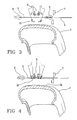
- Angular rotation of arms 28 causes rotation of the respective presser elements 14, 10 between a rest position at which, as shown in Fig. 3 , they are moved apart from a longitudinal movement trajectory imposed to the continuous ribbon-like element 6 by the grip member 8, and a work position at which, as shown in Fig. 4 , they are disposed on said movement trajectory and act in coupling relationship with the guide elements 13 and the continuous ribbon-like element interposed therebetween.
- the presser element 14 is housed within cavity 11 at least partly.
- the guide element is provided with two spacers 37 adapted to come into engagement with the supporting arms 28.
- radial-movement devices designed to cause translation of each laying assembly 9, 9', once coupling between rollers 14, 10 and guide element 13 has occurred, radially close to or away from the outer surface 3a of the toroidal support 3.
- transverse-movement devices not shown too as they can be made in any convenient manner, and which operate on arms 28 or arms 33 for example, to cause translation of each laying assembly 9, 9', once the above mentioned coupling has occurred, between a first operating condition at which, as shown in Fig. 5 , they are disposed close to each other and a second operating condition at which, as shown in Fig. 6 , they are spaced apart from an equatorial plane of the toroidal support 3.
- the grip member 8 is brought to the first work position to engage the final end 6a of the continuous ribbon-like element 6 close to the cutting member 7 ( Fig. 3 ).
- the grip member 8 reaches the second work position, angular rotation of the supporting arms 28 is caused, so as to bring the presser elements 14, 10 in engagement relationship with the continuous ribbon-like element 6 driven by the grip member itself, and with the respective guide elements 13 under it.
- the presser elements 14, 10 are brought into coupling relationship with the respective guide elements 13.
- the cutting member 7 is actuated for carrying out cutting of the strip-like element 5.
- the guide elements co-operate with the first presser rollers 14 to retain the strip-like element 5, transversely stretched out in a substantially centred position relative to the equatorial plane of the toroidal support 3.
- simultaneous translation of the first 14 and second 10 presser rollers is determined along the strip-like segment 5, away from the equatorial plane, so as to determine application of the strip-like element 5 onto the toroidal support 3, over the whole length thereof, by a pressing action progressively extending towards the opposite ends of the strip-like element itself, starting from the central portion of the latter.
- an angular rotation of the toroidal support 3 is caused around its geometric axis X-X according to a predetermined angular pitch, to prepare it for application of a new strip-like element 5.
- Sequential repetition of the above described operations causes formation of belt 2 made up of at least one layer having a continuous circumferential extension around the geometric rotation axis X-X and formed of a plurality of strip-like elements 5 distributed in side by side relationship along the circumferential extension of the toroidal support 3.
Landscapes
- Engineering & Computer Science (AREA)
- Mechanical Engineering (AREA)
- Tyre Moulding (AREA)
- Body Structure For Vehicles (AREA)
Claims (9)
- Vorrichtung zur Herstellung einer Verstärkungsstruktur für Fahrzeugräder, umfassend:eine Zufuhreinheit (4) zum Zuführen von streifenförmigen Elementen (5), wobei jedes schnurförmige Elemente umfasst, welche parallel zueinander angeordnet sind und wenigstens teilweise mit wenigstens einer Schicht eines Elastomermaterials beschichtet sind;eine Ablegeeinheit (100), welche wenigstens eine Ablageanordnung (9, 9') umfasst, um jedes der streifenförmigen Elemente (5) gemäß einem bestimmten Ablagewinkel (α) relativ zu einer Umfangserstreckungsrichtung des Toroidträgers selbst auf einen Toroidträger (3) aufzubringen,;wobei die Ablageanordnung (9, 9') wenigstens ein Druckelement (14), das in einer Gegenbeziehung gegen die äußere Oberfläche (3a) des Toroidträgers (3) bewegbar ist, und wenigstens ein Führungselement (13) umfasst, um das streifenförmige Element (5) während des Ablegens desselbigen zu führen, wobei das Führungselement (13) wenigstens einen Hohlraum (11) umfasst, in dem das Druckelement (14) wenigstens teilweise während des Ablegens des streifenförmigen Elements (5) aufgenommen ist;dadurch gekennzeichnet, dass jede Ablageanordnung (9, 9') ferner wenigstens ein zweites Druckelement (10) umfasst, das bezüglich des ersten Druckelements (14) stromabwärts angeordnet ist, um das streifenförmige Element (5) auf die Außenoberfläche (3a) des Toroidträgers (3) über die gesamte Breite davon abzulegen.
- Vorrichtung nach Anspruch 1, bei der das Führungselement (13) eine C-förmige Gestalt aufweist.
- Vorrichtung nach Anspruch 1, bei der das Führungselement (13) einen Hauptkörper (2) und zwei Zinken (23) umfasst, welche den Hohlraum (11) gemeinsam mit dem Hauptkörper (2) definieren.
- Vorrichtung nach Anspruch 3, bei der die Zinken (23) auf eine unabhängige Weise schwenkbar an dem Hauptkörper (2) angebracht sind, und wobei das Führungselement (13) Federmittel (7) umfasst, welche wirken, um ein Ende von jedem der Zinken (23) während des Ablegens des streifenförmigen Elements (5) in einer Gegenbeziehung zum Toroidträger zu halten.
- Vorrichtung nach Anspruch 1, bei der das wenigstens eine zweite Druckelement (10) aus zwei Druckelementen für jede Ablageanordnung (9, 9') besteht und diese auf eine unabhängige Weise angebracht sind.
- Vorrichtung nach Anspruch 5, bei der die Gesamtbreite der zweiten Druckrollen (10) größer oder gleich der Breite des abzulegenden streifenförmigen Elements (5) ist.
- Vorrichtung nach Anspruch 1 oder 5, bei der ein zweites Federmittel (39) vorgesehen ist, um das zweite Druckelement (10) in einer Gegenbeziehung gegen die Außenoberfläche (3a) des Toroidträgers (3) während des Ablegens des streifenförmigen Elements (5) zu halten.
- Verfahren zur Herstellung von Reifen auf einem Toroidträger, wobei die Reifen eine Verstärkungsstruktur umfassen, die aus wenigstens einer Schicht gefertigt ist, die eine kontinuierliche Umfangserstreckung um die geometrische Drehachse (X-X) eines Toroidträgers (3) aufweist und aus einer Mehrzahl von streifenförmigen Elementen (5) ausgebildet ist, die mit einer gegenseitigen Seite-an-Seite-Beziehung entlang der Umfangserstreckung des Toroidträgers (3), der eine Außenoberfläche (3a) umfasst, verteilt sind,
wobei das Verfahren die folgenden Schritte umfasst:(a) Bringen von zwei ersten Druckelementen (14) in eine Kopplungsbeziehung mit zwei entsprechenden Führungselementen (13), um zwei Ablageanordnungen (9, 9') so auszubilden, um ein streifenförmiges Element (5) zu halten;(b) Verschieben der Ablageanordnungen (9, 9') zum Toroidträger (3), sodass das streifenförmige Element (5) radial in die Nähe zum Toroidträger (3) bewegt wird, bis dieses mit der Außenoberfläche (3a) des Toroidträgers (3) in Kontakt gerät, wodurch ermöglicht wird, dass dieses an dessen mittleren Abschnitt in die Nähe der Äquatorebene des Toroidträgers (3) gedrückt wird;(c) Bewegen der Ablageanordnungen (9, 9') voneinander weg, um die ersten Druckelemente (14) gleichzeitig gemeinsam mit dem streifenförmigen Element (5) weg von der Äquatorebene zu verschieben, um die Aufbringung des streifenförmigen Elements (5) auf eine solche Weise zu bewirken, dass das streifenförmige Element von den Ablageanordnungen im Wesentlichen entlang dessen gesamter Längserstreckung gehalten und geführt wird;(d) winkelförmiges Drehen des Toroidträgers (3) um eine geometrische Achse X-X davon, gemäß einem bestimmten Winkelabstand, um diesen für das Aufbringen eines neuen streifenförmigen Elements (5) vorzubereiten;(e) Sequentielles Wiederholen der Schritte (a) bis (d), um die Verstärkungsstruktur zu erhalten;dadurch gekennzeichnet, dass
im Schritt (a) wenigstens zwei zweite Druckelemente (10) mit dem streifenförmigen Element (5) in Eingriff gebracht werden, wobei jedes davon bezüglich des ersten Druckelements (14) stromabwärts angeordnet ist, um das streifenförmige Element (5) auf die Außenoberfläche (3a) des Toroidträgers (3) über die gesamte Breite davon abzulegen. - Verfahren nach Anspruch 8, bei dem während des Schritts (a) jedes erste Druckelement (14) wenigstens teilweise in einem Hohlraum (11), der in dem entsprechenden Führungselement (13) ausgebildet ist, aufgenommen ist.
Applications Claiming Priority (1)
| Application Number | Priority Date | Filing Date | Title |
|---|---|---|---|
| PCT/IB2006/002070 WO2008015486A1 (en) | 2006-07-28 | 2006-07-28 | Process and apparatus for manufacturing a reinforcing structure for tyres of vehicles |
Publications (2)
| Publication Number | Publication Date |
|---|---|
| EP2046567A1 EP2046567A1 (de) | 2009-04-15 |
| EP2046567B1 true EP2046567B1 (de) | 2010-11-03 |
Family
ID=37871886
Family Applications (1)
| Application Number | Title | Priority Date | Filing Date |
|---|---|---|---|
| EP06795172A Active EP2046567B1 (de) | 2006-07-28 | 2006-07-28 | Verfahren und vorrichtung zur herstellung einer verstärkungsstruktur für fahrzeugreifen |
Country Status (6)
| Country | Link |
|---|---|
| US (1) | US8342220B2 (de) |
| EP (1) | EP2046567B1 (de) |
| CN (1) | CN101511572B (de) |
| AT (1) | ATE486712T1 (de) |
| DE (1) | DE602006018079D1 (de) |
| WO (1) | WO2008015486A1 (de) |
Families Citing this family (4)
| Publication number | Priority date | Publication date | Assignee | Title |
|---|---|---|---|---|
| KR101331920B1 (ko) * | 2007-09-10 | 2013-11-21 | 피렐리 타이어 소시에떼 퍼 아찌오니 | 차량 타이어용 보강구조를 만드는 공정 및 장치 |
| BRPI0722279B1 (pt) | 2007-11-30 | 2018-09-25 | Pirelli | método de construção de pelo menos uma lona de carcaça, processo para fabricação de pneus, e, aparelho para fabricação de pneus |
| US9527256B2 (en) * | 2009-10-13 | 2016-12-27 | Pirelli Tyre S.P.A. | Process and apparatus for building tyres for vehicle wheels |
| IT1403131B1 (it) | 2010-12-14 | 2013-10-04 | Pirelli | Processo ed apparato per realizzare una struttura di rinforzo di un pneumatico per ruote di veicoli. |
Family Cites Families (20)
| Publication number | Priority date | Publication date | Assignee | Title |
|---|---|---|---|---|
| US3321105A (en) * | 1964-02-04 | 1967-05-23 | Flinchbaugh Products Inc | Label dispenser |
| US3990933A (en) * | 1974-01-09 | 1976-11-09 | Minnesota Mining And Manufacturing Company | Tape applying device |
| JPH05124131A (ja) * | 1991-10-30 | 1993-05-21 | Bridgestone Corp | 帯状部材の巻き付け装置 |
| JPH07164559A (ja) * | 1993-12-13 | 1995-06-27 | Toyo Tire & Rubber Co Ltd | 自動車タイヤのキャッププライ成形装置 |
| US5979531A (en) * | 1997-10-01 | 1999-11-09 | Mcdonnell Douglas Corporation | Bi-directional fiber placement head |
| DE69812900T2 (de) | 1997-10-03 | 2004-02-26 | Bridgestone Corp. | Gerät zum formen einer reifenverstärkungslage. |
| ES2200146T3 (es) | 1997-11-28 | 2004-03-01 | Pirelli Pneumatici Societa' Per Azioni | Procedimiento para la fabricacion de neumaticos para ruedas de vehiculos. |
| ES2195109T3 (es) | 1997-12-30 | 2003-12-01 | Pirelli | Procedimiento para la fabricacion de neumaticos para ruedas de vehiculos. |
| US6026883A (en) * | 1998-04-30 | 2000-02-22 | Alliant Techsystems, Inc. | Self-contained apparatus for fiber element placement |
| US6763868B1 (en) | 1998-07-31 | 2004-07-20 | Pirelli Pneumatici S.P.A. | Tire for a two-wheeled vehicle and carcass structure for the tire |
| US6457504B1 (en) | 1998-07-31 | 2002-10-01 | Pirelli Pneumatici S.P.A. | Carcass structure for vehicle tires |
| US6941992B2 (en) | 1998-10-30 | 2005-09-13 | Pirelli Pneumatici S.P.A. | Tire for a vehicle wheel and method of manufacturing the tire |
| EP1147007B1 (de) * | 1999-11-26 | 2004-05-19 | Pirelli Pneumatici S.p.A. | Verfahren und vorrichtung zur herstellung einer verstärkungsstruktur für fahrzeugluftreifen |
| FR2815287A1 (fr) * | 2000-10-18 | 2002-04-19 | Sedepro | Fabrication d'une bandelette par extrusion d'un tube puis aplatissement du tube |
| ES2286252T3 (es) * | 2001-01-12 | 2007-12-01 | Bridgestone Corporation | Metodo de fabricacion de un elemento estructural de una cubierta, y aparato para el mismo. |
| JP4787430B2 (ja) * | 2001-07-23 | 2011-10-05 | 株式会社ブリヂストン | タイヤ用コード補強層の形成方法 |
| BR0116839A (pt) * | 2001-11-27 | 2004-02-03 | Pirelli | Método para produzir uma estrutura de cinta para pneus de veìculo, e, pneu para veìculo motorizado |
| AU2003232838A1 (en) | 2002-06-03 | 2003-12-19 | Michelin Recherche Et Techniques S.A. | Device for producing a reinforcing structure for a tyre, comprising a strip turning mechanism |
| EP1541326A4 (de) | 2002-07-25 | 2006-04-12 | Bridgestone Corp | Vorrichtung zur befestigung einer reifenkomponente |
| US7462252B2 (en) * | 2004-06-22 | 2008-12-09 | Illininois Tool Works Inc. | Label applicator with single air cylinder actuator and spring-loaded hinged pad |
-
2006
- 2006-07-28 WO PCT/IB2006/002070 patent/WO2008015486A1/en not_active Ceased
- 2006-07-28 US US12/309,683 patent/US8342220B2/en active Active
- 2006-07-28 AT AT06795172T patent/ATE486712T1/de not_active IP Right Cessation
- 2006-07-28 CN CN2006800558647A patent/CN101511572B/zh active Active
- 2006-07-28 EP EP06795172A patent/EP2046567B1/de active Active
- 2006-07-28 DE DE602006018079T patent/DE602006018079D1/de active Active
Also Published As
| Publication number | Publication date |
|---|---|
| CN101511572A (zh) | 2009-08-19 |
| DE602006018079D1 (de) | 2010-12-16 |
| ATE486712T1 (de) | 2010-11-15 |
| CN101511572B (zh) | 2012-07-25 |
| WO2008015486A1 (en) | 2008-02-07 |
| US20090236029A1 (en) | 2009-09-24 |
| US8342220B2 (en) | 2013-01-01 |
| EP2046567A1 (de) | 2009-04-15 |
Similar Documents
| Publication | Publication Date | Title |
|---|---|---|
| EP1147007B1 (de) | Verfahren und vorrichtung zur herstellung einer verstärkungsstruktur für fahrzeugluftreifen | |
| EP2200814B1 (de) | Verfahren und vorrichtung zur herstellung einer verstärkungsstruktur für fahrzeugreifen | |
| US10899095B2 (en) | Process and apparatus for building tyres for vehicle wheels | |
| KR101369386B1 (ko) | 차륜용 타이어 제조 방법 및 장치 | |
| JP5265251B2 (ja) | コード切断装置 | |
| US20100200151A1 (en) | Process and apparatus for building pneumatic tyres | |
| US8342220B2 (en) | Process and apparatus for manufacturing a reinforcing structure for tyres of vehicles | |
| US9314982B2 (en) | Process and apparatus for manufacturing a reinforcing structure for tyres of vehicles | |
| EP2200815B1 (de) | Verfahren zur Herstellung einer Verstärkungsstruktur für Fahrzeugreifen | |
| EP1901915B1 (de) | Verfahren zur herstellung eines reifens und vorrichtung zum anordnen eines verstärkungselements auf einer formstütze | |
| EP3487693B1 (de) | Verfahren und vorrichtung zur herstellung von reifen für fahrzeugräder | |
| US20120241065A1 (en) | Process for building tyres for vehicle wheels and tyre for vehicle wheels | |
| JP5215047B2 (ja) | シングルラインプライの製造方法 |
Legal Events
| Date | Code | Title | Description |
|---|---|---|---|
| PUAI | Public reference made under article 153(3) epc to a published international application that has entered the european phase |
Free format text: ORIGINAL CODE: 0009012 |
|
| 17P | Request for examination filed |
Effective date: 20090121 |
|
| AK | Designated contracting states |
Kind code of ref document: A1 Designated state(s): AT BE BG CH CY CZ DE DK EE ES FI FR GB GR HU IE IS IT LI LT LU LV MC NL PL PT RO SE SI SK TR |
|
| AX | Request for extension of the european patent |
Extension state: AL BA HR MK RS |
|
| 17Q | First examination report despatched |
Effective date: 20090806 |
|
| GRAP | Despatch of communication of intention to grant a patent |
Free format text: ORIGINAL CODE: EPIDOSNIGR1 |
|
| DAX | Request for extension of the european patent (deleted) | ||
| GRAS | Grant fee paid |
Free format text: ORIGINAL CODE: EPIDOSNIGR3 |
|
| GRAA | (expected) grant |
Free format text: ORIGINAL CODE: 0009210 |
|
| AK | Designated contracting states |
Kind code of ref document: B1 Designated state(s): AT BE BG CH CY CZ DE DK EE ES FI FR GB GR HU IE IS IT LI LT LU LV MC NL PL PT RO SE SI SK TR |
|
| REG | Reference to a national code |
Ref country code: GB Ref legal event code: FG4D |
|
| REG | Reference to a national code |
Ref country code: CH Ref legal event code: EP |
|
| REG | Reference to a national code |
Ref country code: IE Ref legal event code: FG4D |
|
| REF | Corresponds to: |
Ref document number: 602006018079 Country of ref document: DE Date of ref document: 20101216 Kind code of ref document: P |
|
| REG | Reference to a national code |
Ref country code: RO Ref legal event code: EPE |
|
| REG | Reference to a national code |
Ref country code: NL Ref legal event code: VDEP Effective date: 20101103 |
|
| LTIE | Lt: invalidation of european patent or patent extension |
Effective date: 20101103 |
|
| PG25 | Lapsed in a contracting state [announced via postgrant information from national office to epo] |
Ref country code: LT Free format text: LAPSE BECAUSE OF FAILURE TO SUBMIT A TRANSLATION OF THE DESCRIPTION OR TO PAY THE FEE WITHIN THE PRESCRIBED TIME-LIMIT Effective date: 20101103 |
|
| PG25 | Lapsed in a contracting state [announced via postgrant information from national office to epo] |
Ref country code: FI Free format text: LAPSE BECAUSE OF FAILURE TO SUBMIT A TRANSLATION OF THE DESCRIPTION OR TO PAY THE FEE WITHIN THE PRESCRIBED TIME-LIMIT Effective date: 20101103 Ref country code: SE Free format text: LAPSE BECAUSE OF FAILURE TO SUBMIT A TRANSLATION OF THE DESCRIPTION OR TO PAY THE FEE WITHIN THE PRESCRIBED TIME-LIMIT Effective date: 20101103 Ref country code: NL Free format text: LAPSE BECAUSE OF FAILURE TO SUBMIT A TRANSLATION OF THE DESCRIPTION OR TO PAY THE FEE WITHIN THE PRESCRIBED TIME-LIMIT Effective date: 20101103 Ref country code: LV Free format text: LAPSE BECAUSE OF FAILURE TO SUBMIT A TRANSLATION OF THE DESCRIPTION OR TO PAY THE FEE WITHIN THE PRESCRIBED TIME-LIMIT Effective date: 20101103 Ref country code: PT Free format text: LAPSE BECAUSE OF FAILURE TO SUBMIT A TRANSLATION OF THE DESCRIPTION OR TO PAY THE FEE WITHIN THE PRESCRIBED TIME-LIMIT Effective date: 20110303 Ref country code: BG Free format text: LAPSE BECAUSE OF FAILURE TO SUBMIT A TRANSLATION OF THE DESCRIPTION OR TO PAY THE FEE WITHIN THE PRESCRIBED TIME-LIMIT Effective date: 20110203 Ref country code: IS Free format text: LAPSE BECAUSE OF FAILURE TO SUBMIT A TRANSLATION OF THE DESCRIPTION OR TO PAY THE FEE WITHIN THE PRESCRIBED TIME-LIMIT Effective date: 20110303 Ref country code: AT Free format text: LAPSE BECAUSE OF FAILURE TO SUBMIT A TRANSLATION OF THE DESCRIPTION OR TO PAY THE FEE WITHIN THE PRESCRIBED TIME-LIMIT Effective date: 20101103 Ref country code: SI Free format text: LAPSE BECAUSE OF FAILURE TO SUBMIT A TRANSLATION OF THE DESCRIPTION OR TO PAY THE FEE WITHIN THE PRESCRIBED TIME-LIMIT Effective date: 20101103 |
|
| PG25 | Lapsed in a contracting state [announced via postgrant information from national office to epo] |
Ref country code: GR Free format text: LAPSE BECAUSE OF FAILURE TO SUBMIT A TRANSLATION OF THE DESCRIPTION OR TO PAY THE FEE WITHIN THE PRESCRIBED TIME-LIMIT Effective date: 20110204 |
|
| PG25 | Lapsed in a contracting state [announced via postgrant information from national office to epo] |
Ref country code: EE Free format text: LAPSE BECAUSE OF FAILURE TO SUBMIT A TRANSLATION OF THE DESCRIPTION OR TO PAY THE FEE WITHIN THE PRESCRIBED TIME-LIMIT Effective date: 20101103 Ref country code: ES Free format text: LAPSE BECAUSE OF FAILURE TO SUBMIT A TRANSLATION OF THE DESCRIPTION OR TO PAY THE FEE WITHIN THE PRESCRIBED TIME-LIMIT Effective date: 20110214 Ref country code: CZ Free format text: LAPSE BECAUSE OF FAILURE TO SUBMIT A TRANSLATION OF THE DESCRIPTION OR TO PAY THE FEE WITHIN THE PRESCRIBED TIME-LIMIT Effective date: 20101103 Ref country code: BE Free format text: LAPSE BECAUSE OF FAILURE TO SUBMIT A TRANSLATION OF THE DESCRIPTION OR TO PAY THE FEE WITHIN THE PRESCRIBED TIME-LIMIT Effective date: 20101103 |
|
| PG25 | Lapsed in a contracting state [announced via postgrant information from national office to epo] |
Ref country code: SK Free format text: LAPSE BECAUSE OF FAILURE TO SUBMIT A TRANSLATION OF THE DESCRIPTION OR TO PAY THE FEE WITHIN THE PRESCRIBED TIME-LIMIT Effective date: 20101103 Ref country code: PL Free format text: LAPSE BECAUSE OF FAILURE TO SUBMIT A TRANSLATION OF THE DESCRIPTION OR TO PAY THE FEE WITHIN THE PRESCRIBED TIME-LIMIT Effective date: 20101103 Ref country code: DK Free format text: LAPSE BECAUSE OF FAILURE TO SUBMIT A TRANSLATION OF THE DESCRIPTION OR TO PAY THE FEE WITHIN THE PRESCRIBED TIME-LIMIT Effective date: 20101103 |
|
| PLBE | No opposition filed within time limit |
Free format text: ORIGINAL CODE: 0009261 |
|
| STAA | Information on the status of an ep patent application or granted ep patent |
Free format text: STATUS: NO OPPOSITION FILED WITHIN TIME LIMIT |
|
| 26N | No opposition filed |
Effective date: 20110804 |
|
| REG | Reference to a national code |
Ref country code: DE Ref legal event code: R097 Ref document number: 602006018079 Country of ref document: DE Effective date: 20110804 |
|
| PG25 | Lapsed in a contracting state [announced via postgrant information from national office to epo] |
Ref country code: MC Free format text: LAPSE BECAUSE OF NON-PAYMENT OF DUE FEES Effective date: 20110731 |
|
| REG | Reference to a national code |
Ref country code: CH Ref legal event code: PL |
|
| REG | Reference to a national code |
Ref country code: IE Ref legal event code: MM4A |
|
| PG25 | Lapsed in a contracting state [announced via postgrant information from national office to epo] |
Ref country code: CH Free format text: LAPSE BECAUSE OF NON-PAYMENT OF DUE FEES Effective date: 20110731 Ref country code: LI Free format text: LAPSE BECAUSE OF NON-PAYMENT OF DUE FEES Effective date: 20110731 |
|
| PG25 | Lapsed in a contracting state [announced via postgrant information from national office to epo] |
Ref country code: IE Free format text: LAPSE BECAUSE OF NON-PAYMENT OF DUE FEES Effective date: 20110728 |
|
| PG25 | Lapsed in a contracting state [announced via postgrant information from national office to epo] |
Ref country code: CY Free format text: LAPSE BECAUSE OF EXPIRATION OF PROTECTION Effective date: 20101103 Ref country code: LU Free format text: LAPSE BECAUSE OF NON-PAYMENT OF DUE FEES Effective date: 20110728 |
|
| PG25 | Lapsed in a contracting state [announced via postgrant information from national office to epo] |
Ref country code: TR Free format text: LAPSE BECAUSE OF FAILURE TO SUBMIT A TRANSLATION OF THE DESCRIPTION OR TO PAY THE FEE WITHIN THE PRESCRIBED TIME-LIMIT Effective date: 20101103 |
|
| PG25 | Lapsed in a contracting state [announced via postgrant information from national office to epo] |
Ref country code: HU Free format text: LAPSE BECAUSE OF FAILURE TO SUBMIT A TRANSLATION OF THE DESCRIPTION OR TO PAY THE FEE WITHIN THE PRESCRIBED TIME-LIMIT Effective date: 20101103 |
|
| REG | Reference to a national code |
Ref country code: FR Ref legal event code: PLFP Year of fee payment: 11 |
|
| REG | Reference to a national code |
Ref country code: FR Ref legal event code: PLFP Year of fee payment: 12 |
|
| REG | Reference to a national code |
Ref country code: FR Ref legal event code: PLFP Year of fee payment: 13 |
|
| PGFP | Annual fee paid to national office [announced via postgrant information from national office to epo] |
Ref country code: DE Payment date: 20250729 Year of fee payment: 20 |
|
| PGFP | Annual fee paid to national office [announced via postgrant information from national office to epo] |
Ref country code: IT Payment date: 20250721 Year of fee payment: 20 |
|
| PGFP | Annual fee paid to national office [announced via postgrant information from national office to epo] |
Ref country code: GB Payment date: 20250728 Year of fee payment: 20 |
|
| PGFP | Annual fee paid to national office [announced via postgrant information from national office to epo] |
Ref country code: FR Payment date: 20250728 Year of fee payment: 20 |
|
| PGFP | Annual fee paid to national office [announced via postgrant information from national office to epo] |
Ref country code: RO Payment date: 20250707 Year of fee payment: 20 |