EP2046613B1 - Dispositif de levage - Google Patents
Dispositif de levage Download PDFInfo
- Publication number
- EP2046613B1 EP2046613B1 EP07801153A EP07801153A EP2046613B1 EP 2046613 B1 EP2046613 B1 EP 2046613B1 EP 07801153 A EP07801153 A EP 07801153A EP 07801153 A EP07801153 A EP 07801153A EP 2046613 B1 EP2046613 B1 EP 2046613B1
- Authority
- EP
- European Patent Office
- Prior art keywords
- shaft
- diameter
- lifting device
- hollow shaft
- lifting
- Prior art date
- Legal status (The legal status is an assumption and is not a legal conclusion. Google has not performed a legal analysis and makes no representation as to the accuracy of the status listed.)
- Not-in-force
Links
Images

Classifications
-
- B—PERFORMING OPERATIONS; TRANSPORTING
- B60—VEHICLES IN GENERAL
- B60S—SERVICING, CLEANING, REPAIRING, SUPPORTING, LIFTING, OR MANOEUVRING OF VEHICLES, NOT OTHERWISE PROVIDED FOR
- B60S9/00—Ground-engaging vehicle fittings for supporting, lifting, or manoeuvring the vehicle, wholly or in part, e.g. built-in jacks
- B60S9/02—Ground-engaging vehicle fittings for supporting, lifting, or manoeuvring the vehicle, wholly or in part, e.g. built-in jacks for only lifting or supporting
- B60S9/04—Ground-engaging vehicle fittings for supporting, lifting, or manoeuvring the vehicle, wholly or in part, e.g. built-in jacks for only lifting or supporting mechanically
- B60S9/06—Ground-engaging vehicle fittings for supporting, lifting, or manoeuvring the vehicle, wholly or in part, e.g. built-in jacks for only lifting or supporting mechanically of screw-and-nut type
- B60S9/08—Ground-engaging vehicle fittings for supporting, lifting, or manoeuvring the vehicle, wholly or in part, e.g. built-in jacks for only lifting or supporting mechanically of screw-and-nut type the screw axis being substantially vertical
-
- B—PERFORMING OPERATIONS; TRANSPORTING
- B60—VEHICLES IN GENERAL
- B60S—SERVICING, CLEANING, REPAIRING, SUPPORTING, LIFTING, OR MANOEUVRING OF VEHICLES, NOT OTHERWISE PROVIDED FOR
- B60S9/00—Ground-engaging vehicle fittings for supporting, lifting, or manoeuvring the vehicle, wholly or in part, e.g. built-in jacks
- B60S9/02—Ground-engaging vehicle fittings for supporting, lifting, or manoeuvring the vehicle, wholly or in part, e.g. built-in jacks for only lifting or supporting
- B60S9/04—Ground-engaging vehicle fittings for supporting, lifting, or manoeuvring the vehicle, wholly or in part, e.g. built-in jacks for only lifting or supporting mechanically
Definitions
- the present invention relates to a lifting device, in particular seat post or the like, according to the preamble of claim 1.
- Lifting devices of the type mentioned are used in the application as a seat post, for example, as height-adjustable support devices for so-called “semitrailers” when they are parked independently of a towing vehicle.
- For the operation of the lifting devices prove in particular a simple operation and the most compact design of the lifting devices advantage.
- On both the design of the lifting gear has significant influence, because the lifting gear on the one hand substantially co-determined by its outside provided on the shaft tube positioning the outer dimensions of the lifting device and on the other due to the design of the lifting gear as a simple and safe performance of the switching operation to select the appropriate gear ratio is of great importance.
- a lifting gear of a seat post with a drive and an output shaft assembly each with a small diameter and a diameter large gear known.
- a large diameter drive gear forms a hollow shaft, which is mounted in a transmission housing.
- a shift shaft allows shifting a small diameter drive gear and thus selectively engaging the pinion with a large diameter output gear or with the hollow shaft of the large diameter drive gear.
- the present invention is therefore based on the object to propose a lifting device whose screw jack on the one hand has a compact as possible, the outer dimensions of the lifting device only slightly superior training and on the other hand, a simple operation, in particular with regard to the implementation of the switching operation allows.
- the drive shaft assembly has a mounted in a gear housing hollow shaft and a coaxial with the hollow shaft, axially displaceable and mounted in the transmission housing shift shaft, wherein the hollow shaft for rotationally rigid arrangement of the large diameter drive gear and the shift shaft for the rotationally rigid arrangement of the small diameter drive gear, and the hollow shaft and the switching shaft are provided with engagement means engageable by means of axial displacement for changing the gear ratio.
- the inventively designed lifting device allows due to the configuration of the drive shaft assembly as a coupling device a spatially immediately adjacent arrangement of diametrically- ⁇ en gear of the output shaft and the large diameter gear of the drive shaft with the smallest possible axial distance from each other, as arranged on the hollow shaft diameter gear of the drive shaft assembly constantly runs along and the Control of the power flow is performed by an axial switching movement of the switching shaft relative to the hollow shaft. From this axially adjacent arrangement of the large diameter gears of the drive shaft assembly and the output shaft assembly results in a correspondingly flat construction of the lifting gear.
- the drive gear has an engagement length greater than an engagement distance between the engagement means of the shift shaft and the engagement means of the hollow shaft, it is ensured that the engagement means engage each other before the drive gear is disengaged from the output shaft assembly. It can therefore come to any gear position in which the power flow is interrupted in the manual transmission.
- the hollow shaft of the drive shaft assembly and the output shaft assembly each have a matching diameter in the range of the large diameter gear, it is possible that both the hollow shaft of the drive shaft assembly and the output shaft assembly provided with identical holes gears can be used, which is correspondingly positive affects the manufacturing costs.
- the large diameter gears have a matching outer diameter and a matching module, the large diameter gears are identically executable, so that hereby a reduced number of different parts of the Lifting device or the lifting gear is connected, resulting in a further cost savings.
- the savings in manufacturing are particularly effective when the large diameter gears are composed of matching trained annular disk elements, so that the number of different parts can be further reduced.
- the engagement means are each formed as a cam means having at least one cam lobe which engage with suitable relative rotation of the shift shaft and the hollow shaft with each other, is a switching operation for transferring the lifting gear from a load gear in which the small drive gear of the drive shaft assembly with the large diameter gear the output shaft assembly meshes in a high gear, in which the large diameter gear of the drive shaft assembly meshes with the small diameter gear of the output shaft assembly, particularly easy to carry out, since according to the angular displacement of the drive cam, the probability that the switching operation without mutual mutual locking of the driving cam is feasible regardless of the rotational angle relative position of the hollow shaft relative to the switching shaft is very large.
- cam device of the selector shaft is formed from a driver pin radially penetrating the selector shaft, the radial ends of which form camshafts which project radially beyond the selector shaft diameter.
- cam device of the hollow shaft For functionally complementary design of the cam device of the hollow shaft, it proves to be advantageous if they consist of two, offset by 180 degrees on the inner circumference of the hollow shaft arranged driving cams.
- the hollow shaft as a molded part, such as cast or deep drawn part, it proves to be advantageous if the driving cams are formed integrally with the hollow shaft.
- the switching shaft in Verlastungskonfiguration the lifting device in load position penetrates two adjacent wall portions of the shaft tube and the support tube so as to form an additional safety valve, which prevents the support tube, for example due to vibrations during the drive of the vehicle, runs on the Hubspindel.
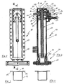
- a lifting device 10 with a shaft tube 11 and a coaxially arranged in the shaft tube 11 support tube 12.
- the shaft tube 11 is in accordance with the in Fig. 3 executed embodiment, composed of a U-shaped shaft tube profile 13 and a profile 13 to a square tube complementary mounting plate 14, which also forms the rear wall of the shaft tube 11.
- the mounting plate 14 is used for connection to a vehicle chassis and has laterally formed terminal strips 15, 16, a plurality of mounting holes 17, which allow a connection to differently shaped vehicle chassis or in different mounting heights on a vehicle chassis.
- the support tube 12 received in the shaft tube 11 extends substantially over the entire length of the shaft tube 11.
- the shaft tube 11 has, as a quasi-end closure, a pressure plate 18 which serves to receive an upper lifting spindle end 19 of a lifting spindle 20 which extends on a longitudinal axis 21 of the lifting device 10 or of the support tube 12.
- a pressure plate 18 which serves to receive an upper lifting spindle end 19 of a lifting spindle 20 which extends on a longitudinal axis 21 of the lifting device 10 or of the support tube 12.
- Hubspindelende 19 is also located on a shaft collar 22 rotatably mounted Hubspindeliererad 23, which serves to drive the lifting spindle 20 and is supported together with the lifting spindle 20 via a thrust bearing 24 on the pressure plate 18.
- a spindle nut 25 is arranged, which is rotationally rigidly connected to the support tube 12 at its periphery, so that a rotation of the lifting spindle 20 as a result of a drive of the Hubspindeliererads 23 via the threaded engagement of the lifting spindle 20 with the spindle nut 25 depending on the direction of rotation Extending or retracting the support tube 12 from the shaft tube 11 addition or effected in this.
- Hubspindeliererads 23 To drive the Hubspindeliererads 23 is arranged below the pressure plate 18 Hubgetriebe 26, which includes a drive shaft assembly 27 and an output shaft assembly 28 which acts on the Hubspindeltechnikrad 23 includes.
- a foot device 29 At the lower end of the support tube 12 is a foot device 29, which has a connected to a lower end 30 of the support tube 12 foot receptacle 31 and connected to the foot receptacle 31 pivot foot 32.
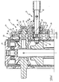
- This in Fig. 5 illustrated lifting gear 26 has the drive shaft assembly 27, comprising a switching shaft 85 and a coaxial with the switching shaft 85 arranged hollow shaft 86.
- On the shift shaft 85 is integrally formed with this a small-diameter drive gear 62 in the present case.
- an entrainment pin 63 Arranged at an axial distance from the drive gear 62 is an entrainment pin 63 which in the present case is inserted into the selector shaft 85 and which forms a driver cam 64 and 65 by two ends projecting beyond the outer diameter of the selector shaft 85.
- the selector shaft 85 is brought out with its shaft end facing away from the lifting spindle 20 from a housing cover 66 of a transmission housing 68 formed by the housing cover 66 and a shaft tube wall region 67. That from the gearbox 68 led out shaft end is formed as a connection end 69 for connecting a crank mechanism or other suitable drive means.
- the designed as a drive shaft switching shaft 85 is located in the in Fig. 5 shown position in "load position” in which the drive gear 62 meshes with a large diameter output gear 70 of the output shaft assembly 28.
- the "load position” that of the lifting spindle 20 facing the end of the switching shaft 85 is guided by overlapping pipe wall portions of the shaft tube 11 and the support tube 12 into the support tube 12.
- a latching device 72 is provided in the region of a arranged in the wall of the shaft tube 11 shaft bearing 71 which engages spring-loaded in locking grooves 73, 74 of the switching shaft 85.
- the drive cams 64, 65 of the shift shaft 85 are in the range of drive cams 75, 76 formed on the inner circumference of the hollow shaft 86, which engage in the Fig. 6 and 7 are shown more clearly.
- the driving cams 75, 76 of the hollow shaft 86 and the driving cams 64, 65 of the switching shaft 85 are radially offset by 180 degrees.
- On a hub area 77 of the hollow shaft 86 is a diameter-large drive gear 78 of the drive shaft assembly 27 arranged rotationally fixed.
- the hollow shaft 86 as in the 6 and 7 represented, in the present case, a splined shaft 79.
- the hollow shaft 86 Adjacent to the hub portion 77 of the hollow shaft 86, the hollow shaft 86 has a bearing collar 80, with which the hollow shaft 86 is rotatably mounted in the housing cover 66 in a floating manner.
- the drive gear 78 is in constant mesh with a small diameter output gear 81 of the output shaft assembly 28.
- the output shaft assembly 28 has the output shaft 82, which serves in the present case at the same time to form the Hubspindelantriebszahnrads 33, and a torsionally rigidly connected to the output shaft 82 bearing pin 83, the at the same time for the formation of the small-diameter driven gear 81 is used.
- For storage of the output shaft assembly 28 of the bearing pin 83 in the gear cover 66 and the output shaft 82 are mounted in the bearing device 35.
- the small drive gear 62 is disengaged from the large diameter output gear 78, and the drive cams 64, 65 of the shift shaft 85 are engaged with the drive cams 75, 76 of the hollow shaft 86, so that the drive torque from the shift shaft 85 via the hollow shaft 86, the large diameter drive gear 78 and the small diameter driven gear 81 is transmitted to the output shaft assembly 28.
- the large diameter output gear 70 runs on the output shaft 82 without load.
- the large diameter drive gear 78 and the large diameter driven gear 70 are each composed of identical ring disk elements 84, each forming a disk-shaped gear segment.
- the different number of annular disk elements 84 is selected according to the different load of the gears 78 and 70 in the load gear or overdrive.
- the gear housing cover 66 is preferably made of a material with good sliding properties, so for example of a suitable cast or sintered material or preferably also of a plastic material.
- the hollow shaft 86 and the bearing pin 83 of the output shaft assembly 28 can be stored directly without use of separate bushings or the like in the housing cover 66 formed bearing receivers 87 and 88.
Landscapes
- Engineering & Computer Science (AREA)
- Mechanical Engineering (AREA)
- Seats For Vehicles (AREA)
- Structure Of Transmissions (AREA)
- Gear Transmission (AREA)
- Noodles (AREA)
- Advancing Webs (AREA)
- Electrical Discharge Machining, Electrochemical Machining, And Combined Machining (AREA)
- Transmission Devices (AREA)
- Prostheses (AREA)
Claims (10)
- Dispositif de levage (10), en particulier un support de remorque ou similaire, comprenant un tube de tige (11) et un tube de support (12) déplaçable par rapport au tube de tige, un mécanisme de levage (26) étant disposé au tube de tige et présentant un agencement d'arbre d'entraînement (27) pour le raccordement d'un dispositif d'entraînement et un agencement d'arbre de sortie (28) pour l'entraînement d'une broche de levage (20) étant disposée dans le tube de support, l'agencement d'arbre d'entraînement et l'agencement d'arbre de sortie présentant chacun au moins une roue dentée de grand diamètre (70, 78) et une roue dentée de petit diamètre (62, 81) pouvant être amenées en engrènement par adhérence l'une avec l'autre afin de générer différents rapports de transmission, l'agencement d'arbre d'entraînement présentant un arbre creux (86) monté dans un carter d'engrenage (68) et un arbre de changement de vitesses (85) disposé coaxialement par rapport à l'arbre creux, étant axialement déplaçable et étant monté dans le carter d'engrenage, l'arbre creux servant pour l'agencement immobile en rotation de la roue dentée d'entraînement de grand diamètre (78) et l'arbre de changement de vitesses servant pour l'agencement immobile en rotation de la roue dentée de petit diamètre (62), et l'arbre creux et l'arbre de changement de vitesses étant munis de dispositifs d'engrènement pouvant être amenés en engrènement de couplage au moyen d'un déplacement axial afin de varier le rapport de transmission,
caractérisé en ce que
les dispositifs d'engrènement sont formés de manière à être indépendants de la roue dentée d'entraînement de petit diamètre (62). - Dispositif de levage selon la revendication 1,
caractérisé en ce que
la roue dentée d'entraînement (62) présente une longueur d'engrènement e qui est dimensionnée plus grande qu'une distance d'engrènement a entre les dispositifs d'engrènement de l'arbre de changement de vitesses (85) et les dispositifs d'engrènement de l'arbre creux (86). - Dispositif de levage selon la revendication 1 ou 2,
caractérisé en ce que
l'arbre creux (86) de l'agencement d'arbre d'entraînement (27) et l'agencement d'arbre de sortie (28) dans la zone de la roue dentée de grand diamètre (70, 78) présentent chacun un diamètre congruent. - Dispositif de levage selon la revendication 3,
caractérisé en ce que
le roues dentées de grand diamètre (70, 78) présentent un diamètre extérieur congruent et un module congruent. - Dispositif de levage selon la revendication 4,
caractérisé en ce que
les roues dentées de grand diamètre (70, 78) sont composées d'éléments de disque annulaire (84) formés de manière congruente. - Dispositif de levage selon l'une quelconque des revendications précédentes,
caractérisé en ce que
chacun des dispositifs d'engrènement est formé en tant que dispositif à cames ayant au moins une came d'entraînement (64, 65; 75, 76) qui, lors d'une rotation relative appropriée de l'arbre de changement de vitesses (85) et de l'arbre creux (86), viennent en engrènement l'un avec l'autre. - Dispositif de levage selon la revendication 6,
caractérisé en ce que
le dispositif à cames de l'arbre de changement de vitesses (85) est formé d'une broche d'entraînement (63) qui pénètre radialement l'arbre de changement de vitesses et dont les extrémités faisant radialement saillie au delà du diamètre de l'arbre de changement de vitesses forment des cames d'entraînement (64, 65). - Dispositif de levage selon la revendication 6,
caractérisé en ce que
le dispositif à cames de l'arbre creux (86) est composé de deux cames d'entraînement (75, 76) qui sont disposées de façon décalée de 180 degrés le long de la circonférence intérieure de l'arbre creux. - Dispositif de levage selon la revendication 8,
caractérisé en ce que
les cames d'entraînement (75, 76) sont formées d'un seul tenant avec l'arbre creux (86). - Dispositif de levage selon l'une quelconque des revendications précédentes,
caractérisé en ce que
l'arbre de changement de vitesses (85), dans la position de petite vitesse et en configuration de transport du dispositif de levage, pénètre deux zones de paroi adjacentes du tube de tige (11) et du tube de support (12).
Priority Applications (1)
| Application Number | Priority Date | Filing Date | Title |
|---|---|---|---|
| PL07801153T PL2046613T3 (pl) | 2006-07-31 | 2007-07-12 | Urządzenie podnośnikowe |
Applications Claiming Priority (2)
| Application Number | Priority Date | Filing Date | Title |
|---|---|---|---|
| DE102006035919A DE102006035919A1 (de) | 2006-07-31 | 2006-07-31 | Hubeinrichtung |
| PCT/DE2007/001247 WO2008014746A1 (fr) | 2006-07-31 | 2007-07-12 | Dispositif de levage |
Publications (2)
| Publication Number | Publication Date |
|---|---|
| EP2046613A1 EP2046613A1 (fr) | 2009-04-15 |
| EP2046613B1 true EP2046613B1 (fr) | 2012-02-22 |
Family
ID=38736073
Family Applications (1)
| Application Number | Title | Priority Date | Filing Date |
|---|---|---|---|
| EP07801153A Not-in-force EP2046613B1 (fr) | 2006-07-31 | 2007-07-12 | Dispositif de levage |
Country Status (10)
| Country | Link |
|---|---|
| US (2) | US20090321696A1 (fr) |
| EP (1) | EP2046613B1 (fr) |
| CN (1) | CN101495348B (fr) |
| AT (1) | ATE546326T1 (fr) |
| CA (1) | CA2659433C (fr) |
| DE (1) | DE102006035919A1 (fr) |
| ES (1) | ES2379402T3 (fr) |
| PL (1) | PL2046613T3 (fr) |
| RU (1) | RU2412836C2 (fr) |
| WO (1) | WO2008014746A1 (fr) |
Families Citing this family (12)
| Publication number | Priority date | Publication date | Assignee | Title |
|---|---|---|---|---|
| US20100213429A1 (en) * | 2009-02-20 | 2010-08-26 | Frank Drake | Jack assembly with multiple degrees of freedom |
| DE202009006892U1 (de) * | 2009-03-16 | 2009-09-03 | Riedl, Reinhold, Dipl.-Ing. | Höhenverstellbare Stütze für Sattelauflieger o.dgl. |
| US10166414B1 (en) * | 2009-05-27 | 2019-01-01 | Richard E. Thaw | Handheld forcible entry device |
| US9517363B1 (en) * | 2009-05-27 | 2016-12-13 | Madeleine Ambron Newman | Powered hand-held forcible entry device |
| DE102011081340B3 (de) * | 2011-08-22 | 2012-12-13 | Saf-Holland Gmbh | Stützvorrichtung für einen Sattelanhänger, umfassend einen Spindelmechanismus mit mehrteiliger Spindel, sowie Sattelanhänger mit einer solchen Stützvorrichtung und einer Spindel zur Verwendung in einer Stützvorrichtung |
| WO2013041917A1 (fr) * | 2011-09-21 | 2013-03-28 | Oms Makina Imalat Sanayi Ticaret Limited Sirketi | Béquille |
| DE102013022132A1 (de) * | 2013-12-24 | 2015-06-25 | Hubert Koschinat | Teleskopstütze mit Spindel und deren Antrieb über Tellerrad mit integriertem Axiallager zur Lastabstützung |
| DE102017122316B4 (de) | 2017-09-26 | 2021-01-21 | Saf-Holland Gmbh | Montagevorrichtung für eine Stützvorrichtung |
| CN111688649A (zh) * | 2020-06-19 | 2020-09-22 | 杭州恒领科技有限公司 | 具有v2x智能天线的运输车辆支承定位装置 |
| US20220355769A1 (en) * | 2021-05-04 | 2022-11-10 | Albert W. MacDonald | Trailer Crank Extension Device for Automated Raising and Lowering of a Trailer |
| US20230303039A1 (en) | 2022-03-28 | 2023-09-28 | Saf-Holland, Inc. | Landing gear assembly |
| US12325387B2 (en) | 2022-03-28 | 2025-06-10 | Saf-Holland, Inc. | Landing gear assembly |
Family Cites Families (14)
| Publication number | Priority date | Publication date | Assignee | Title |
|---|---|---|---|---|
| US4923175A (en) * | 1989-05-19 | 1990-05-08 | Kysor Industrial Corporation | Constant mesh gear box landing gear |
| US5538225A (en) * | 1994-03-31 | 1996-07-23 | Jost International Of Grand Haven Michigan | Landing gear for semitrailers |
| US5435523A (en) * | 1994-10-25 | 1995-07-25 | Wesbar Corporation | Trailer tongue jack |
| US6099016A (en) * | 1997-07-21 | 2000-08-08 | The Binkley Company | Landing gear |
| DE19836635C5 (de) | 1998-08-13 | 2005-07-14 | Jost-Werke Gmbh & Co. Kg | Vorrichtung zum Abstützen eines Aufliegers eines Sattelschleppers |
| DE60038791D1 (de) * | 1999-03-04 | 2008-06-19 | Razor Internat Pty Ltd | Elektrische anhängerabstützung |
| US6267357B1 (en) * | 2000-02-10 | 2001-07-31 | Fulton Performance Products, Inc. | Drop foot jack |
| US20030089898A1 (en) * | 2001-11-15 | 2003-05-15 | Straw Shane A. | Screw nut holder for heavy-duty jack assembly |
| CN1911714B (zh) * | 2002-04-02 | 2010-08-25 | Saf霍兰德公司 | 起落架装置和用于制造起落架装置支架的部件 |
| RU2220090C1 (ru) * | 2002-05-24 | 2003-12-27 | Косенко Михаил Юрьевич | Домкрат для автомобиля |
| DE10244865B4 (de) * | 2002-09-23 | 2004-09-30 | Demag Cranes & Components Gmbh | Kettenzug |
| US20040096271A1 (en) * | 2002-11-19 | 2004-05-20 | Rainer Peter | Quill shaft tensioning coupling |
| DE20305175U1 (de) * | 2003-03-31 | 2003-09-25 | Riedl, Reinhold, Dipl.-Ing., 63897 Miltenberg | Höhenverstellbare Stütze für Sattelauflieger o.dgl. |
| US7121563B1 (en) * | 2005-03-22 | 2006-10-17 | Unique Products & Design Co., Ltd. | Golf cart front-wheel collapsing device |
-
2006
- 2006-07-31 DE DE102006035919A patent/DE102006035919A1/de not_active Withdrawn
-
2007
- 2007-07-12 AT AT07801153T patent/ATE546326T1/de active
- 2007-07-12 PL PL07801153T patent/PL2046613T3/pl unknown
- 2007-07-12 CA CA2659433A patent/CA2659433C/fr not_active Expired - Fee Related
- 2007-07-12 US US12/375,714 patent/US20090321696A1/en not_active Abandoned
- 2007-07-12 RU RU2009106115/11A patent/RU2412836C2/ru not_active IP Right Cessation
- 2007-07-12 WO PCT/DE2007/001247 patent/WO2008014746A1/fr not_active Ceased
- 2007-07-12 ES ES07801153T patent/ES2379402T3/es active Active
- 2007-07-12 EP EP07801153A patent/EP2046613B1/fr not_active Not-in-force
- 2007-07-12 CN CN2007800280532A patent/CN101495348B/zh not_active Expired - Fee Related
-
2012
- 2012-12-27 US US13/728,038 patent/US20130187106A1/en not_active Abandoned
Also Published As
| Publication number | Publication date |
|---|---|
| CA2659433A1 (fr) | 2008-02-07 |
| PL2046613T3 (pl) | 2012-07-31 |
| ATE546326T1 (de) | 2012-03-15 |
| EP2046613A1 (fr) | 2009-04-15 |
| US20130187106A1 (en) | 2013-07-25 |
| RU2009106115A (ru) | 2010-09-10 |
| WO2008014746A1 (fr) | 2008-02-07 |
| DE102006035919A1 (de) | 2008-02-14 |
| RU2412836C2 (ru) | 2011-02-27 |
| US20090321696A1 (en) | 2009-12-31 |
| CA2659433C (fr) | 2013-04-09 |
| CN101495348A (zh) | 2009-07-29 |
| CN101495348B (zh) | 2012-08-15 |
| ES2379402T3 (es) | 2012-04-25 |
Similar Documents
| Publication | Publication Date | Title |
|---|---|---|
| EP2046613B1 (fr) | Dispositif de levage | |
| EP1633994B1 (fr) | Transmission a engrenages planetaires | |
| EP2513524B1 (fr) | Dispositif de commutation pour une boîte de vitesses à engrenages | |
| DE2848284C2 (de) | Getriebe für einen landwirtschaftlich genutzten Traktor mit Vierradantrieb | |
| EP2232107B1 (fr) | Dispositif de changement de vitesse pour boîtes de vitesses à plusieurs étages de véhicules automobiles | |
| DE102019208345B4 (de) | Differentialsperre | |
| EP0800025B1 (fr) | Dispositif de commande pour automatiser le changement de vitesse pour boíte de vitesses manuelle des véhicules automobiles | |
| DE3214862C2 (de) | Stufenlos verstellbares Umschlingungs-Keilriemengetriebe für ein Kraftfahrzeug | |
| EP1627164A1 (fr) | Engrenage planetaire | |
| DE102012207250A1 (de) | Spielarmes Planetengetriebe | |
| EP2513511B1 (fr) | Boîte de vitesse à double embrayage d'un véhicule automobile | |
| DE102009024821B4 (de) | Schaltvorrichtung | |
| WO2022057973A1 (fr) | Transmission à plusieurs rapports dotée d'un différentiel présentant des zones de denture, ainsi qu'unité d'entraînement | |
| EP3339682B1 (fr) | Pignon baladeur pour un dispositif de boîte à pignons baladeurs | |
| DE102012100870B4 (de) | Schaltvorrichtung für ein Schaltgetriebe | |
| WO2020064044A1 (fr) | Unité de transmission pour une transmission de véhicule à moteur dotée d'une roue droite agencée rotative sur un arbre intermédiaire | |
| WO2014044277A1 (fr) | Système de transmission | |
| DE102019131781A1 (de) | Antriebssystem mit im Planetenradsatz implementierter Synchroeinheit als Parksperre | |
| DE102012214084A1 (de) | Schaltvorrichtung eines Kraftfahrzeug-Schaltgetriebes | |
| DE10227741B4 (de) | Geschwindigkeits-Wechselgetriebe | |
| DE102017117600A1 (de) | Pumpenvorrichtung | |
| EP2184510B1 (fr) | Agencement de commutation | |
| DE102018121074A1 (de) | Schaltvorrichtung für ein zweistufiges Schaltgetriebe | |
| DE102022203639A1 (de) | Schaltwalzenanordnung für ein Kraftfahrzeuggetriebe | |
| DE102016210656A1 (de) | Getriebeanordnung für ein Fahrzeug |
Legal Events
| Date | Code | Title | Description |
|---|---|---|---|
| PUAI | Public reference made under article 153(3) epc to a published international application that has entered the european phase |
Free format text: ORIGINAL CODE: 0009012 |
|
| 17P | Request for examination filed |
Effective date: 20090220 |
|
| AK | Designated contracting states |
Kind code of ref document: A1 Designated state(s): AT BE BG CH CY CZ DE DK EE ES FI FR GB GR HU IE IS IT LI LT LU LV MC MT NL PL PT RO SE SI SK TR |
|
| AX | Request for extension of the european patent |
Extension state: AL BA HR MK RS |
|
| RIN1 | Information on inventor provided before grant (corrected) |
Inventor name: MILTENBERGER, ROBERT Inventor name: BIRKHOLZ, HOLGER Inventor name: TRUNK, GERHARD Inventor name: NATTERER, RALF |
|
| 17Q | First examination report despatched |
Effective date: 20100127 |
|
| 17Q | First examination report despatched |
Effective date: 20100803 |
|
| GRAP | Despatch of communication of intention to grant a patent |
Free format text: ORIGINAL CODE: EPIDOSNIGR1 |
|
| DAX | Request for extension of the european patent (deleted) | ||
| GRAS | Grant fee paid |
Free format text: ORIGINAL CODE: EPIDOSNIGR3 |
|
| GRAA | (expected) grant |
Free format text: ORIGINAL CODE: 0009210 |
|
| AK | Designated contracting states |
Kind code of ref document: B1 Designated state(s): AT BE BG CH CY CZ DE DK EE ES FI FR GB GR HU IE IS IT LI LT LU LV MC MT NL PL PT RO SE SI SK TR |
|
| REG | Reference to a national code |
Ref country code: GB Ref legal event code: FG4D Free format text: NOT ENGLISH |
|
| REG | Reference to a national code |
Ref country code: CH Ref legal event code: EP |
|
| REG | Reference to a national code |
Ref country code: AT Ref legal event code: REF Ref document number: 546326 Country of ref document: AT Kind code of ref document: T Effective date: 20120315 |
|
| REG | Reference to a national code |
Ref country code: IE Ref legal event code: FG4D Free format text: LANGUAGE OF EP DOCUMENT: GERMAN |
|
| REG | Reference to a national code |
Ref country code: DE Ref legal event code: R096 Ref document number: 502007009333 Country of ref document: DE Effective date: 20120419 |
|
| REG | Reference to a national code |
Ref country code: ES Ref legal event code: FG2A Ref document number: 2379402 Country of ref document: ES Kind code of ref document: T3 Effective date: 20120425 |
|
| REG | Reference to a national code |
Ref country code: NL Ref legal event code: T3 |
|
| LTIE | Lt: invalidation of european patent or patent extension |
Effective date: 20120222 |
|
| PG25 | Lapsed in a contracting state [announced via postgrant information from national office to epo] |
Ref country code: LT Free format text: LAPSE BECAUSE OF FAILURE TO SUBMIT A TRANSLATION OF THE DESCRIPTION OR TO PAY THE FEE WITHIN THE PRESCRIBED TIME-LIMIT Effective date: 20120222 Ref country code: IS Free format text: LAPSE BECAUSE OF FAILURE TO SUBMIT A TRANSLATION OF THE DESCRIPTION OR TO PAY THE FEE WITHIN THE PRESCRIBED TIME-LIMIT Effective date: 20120622 |
|
| REG | Reference to a national code |
Ref country code: PL Ref legal event code: T3 |
|
| PG25 | Lapsed in a contracting state [announced via postgrant information from national office to epo] |
Ref country code: PT Free format text: LAPSE BECAUSE OF FAILURE TO SUBMIT A TRANSLATION OF THE DESCRIPTION OR TO PAY THE FEE WITHIN THE PRESCRIBED TIME-LIMIT Effective date: 20120622 Ref country code: LV Free format text: LAPSE BECAUSE OF FAILURE TO SUBMIT A TRANSLATION OF THE DESCRIPTION OR TO PAY THE FEE WITHIN THE PRESCRIBED TIME-LIMIT Effective date: 20120222 Ref country code: FI Free format text: LAPSE BECAUSE OF FAILURE TO SUBMIT A TRANSLATION OF THE DESCRIPTION OR TO PAY THE FEE WITHIN THE PRESCRIBED TIME-LIMIT Effective date: 20120222 Ref country code: GR Free format text: LAPSE BECAUSE OF FAILURE TO SUBMIT A TRANSLATION OF THE DESCRIPTION OR TO PAY THE FEE WITHIN THE PRESCRIBED TIME-LIMIT Effective date: 20120523 |
|
| REG | Reference to a national code |
Ref country code: IE Ref legal event code: FD4D |
|
| PG25 | Lapsed in a contracting state [announced via postgrant information from national office to epo] |
Ref country code: CY Free format text: LAPSE BECAUSE OF FAILURE TO SUBMIT A TRANSLATION OF THE DESCRIPTION OR TO PAY THE FEE WITHIN THE PRESCRIBED TIME-LIMIT Effective date: 20120222 |
|
| PG25 | Lapsed in a contracting state [announced via postgrant information from national office to epo] |
Ref country code: CZ Free format text: LAPSE BECAUSE OF FAILURE TO SUBMIT A TRANSLATION OF THE DESCRIPTION OR TO PAY THE FEE WITHIN THE PRESCRIBED TIME-LIMIT Effective date: 20120222 Ref country code: IE Free format text: LAPSE BECAUSE OF FAILURE TO SUBMIT A TRANSLATION OF THE DESCRIPTION OR TO PAY THE FEE WITHIN THE PRESCRIBED TIME-LIMIT Effective date: 20120222 Ref country code: SI Free format text: LAPSE BECAUSE OF FAILURE TO SUBMIT A TRANSLATION OF THE DESCRIPTION OR TO PAY THE FEE WITHIN THE PRESCRIBED TIME-LIMIT Effective date: 20120222 Ref country code: EE Free format text: LAPSE BECAUSE OF FAILURE TO SUBMIT A TRANSLATION OF THE DESCRIPTION OR TO PAY THE FEE WITHIN THE PRESCRIBED TIME-LIMIT Effective date: 20120222 Ref country code: RO Free format text: LAPSE BECAUSE OF FAILURE TO SUBMIT A TRANSLATION OF THE DESCRIPTION OR TO PAY THE FEE WITHIN THE PRESCRIBED TIME-LIMIT Effective date: 20120222 Ref country code: DK Free format text: LAPSE BECAUSE OF FAILURE TO SUBMIT A TRANSLATION OF THE DESCRIPTION OR TO PAY THE FEE WITHIN THE PRESCRIBED TIME-LIMIT Effective date: 20120222 Ref country code: SE Free format text: LAPSE BECAUSE OF FAILURE TO SUBMIT A TRANSLATION OF THE DESCRIPTION OR TO PAY THE FEE WITHIN THE PRESCRIBED TIME-LIMIT Effective date: 20120222 |
|
| PG25 | Lapsed in a contracting state [announced via postgrant information from national office to epo] |
Ref country code: IT Free format text: LAPSE BECAUSE OF FAILURE TO SUBMIT A TRANSLATION OF THE DESCRIPTION OR TO PAY THE FEE WITHIN THE PRESCRIBED TIME-LIMIT Effective date: 20120222 Ref country code: SK Free format text: LAPSE BECAUSE OF FAILURE TO SUBMIT A TRANSLATION OF THE DESCRIPTION OR TO PAY THE FEE WITHIN THE PRESCRIBED TIME-LIMIT Effective date: 20120222 |
|
| PLBE | No opposition filed within time limit |
Free format text: ORIGINAL CODE: 0009261 |
|
| STAA | Information on the status of an ep patent application or granted ep patent |
Free format text: STATUS: NO OPPOSITION FILED WITHIN TIME LIMIT |
|
| 26N | No opposition filed |
Effective date: 20121123 |
|
| PG25 | Lapsed in a contracting state [announced via postgrant information from national office to epo] |
Ref country code: MC Free format text: LAPSE BECAUSE OF NON-PAYMENT OF DUE FEES Effective date: 20120731 |
|
| REG | Reference to a national code |
Ref country code: CH Ref legal event code: PL |
|
| REG | Reference to a national code |
Ref country code: DE Ref legal event code: R097 Ref document number: 502007009333 Country of ref document: DE Effective date: 20121123 |
|
| PG25 | Lapsed in a contracting state [announced via postgrant information from national office to epo] |
Ref country code: CH Free format text: LAPSE BECAUSE OF NON-PAYMENT OF DUE FEES Effective date: 20120731 Ref country code: LI Free format text: LAPSE BECAUSE OF NON-PAYMENT OF DUE FEES Effective date: 20120731 |
|
| PG25 | Lapsed in a contracting state [announced via postgrant information from national office to epo] |
Ref country code: BG Free format text: LAPSE BECAUSE OF FAILURE TO SUBMIT A TRANSLATION OF THE DESCRIPTION OR TO PAY THE FEE WITHIN THE PRESCRIBED TIME-LIMIT Effective date: 20120522 Ref country code: MT Free format text: LAPSE BECAUSE OF FAILURE TO SUBMIT A TRANSLATION OF THE DESCRIPTION OR TO PAY THE FEE WITHIN THE PRESCRIBED TIME-LIMIT Effective date: 20120222 |
|
| PG25 | Lapsed in a contracting state [announced via postgrant information from national office to epo] |
Ref country code: LU Free format text: LAPSE BECAUSE OF NON-PAYMENT OF DUE FEES Effective date: 20120712 |
|
| PG25 | Lapsed in a contracting state [announced via postgrant information from national office to epo] |
Ref country code: HU Free format text: LAPSE BECAUSE OF FAILURE TO SUBMIT A TRANSLATION OF THE DESCRIPTION OR TO PAY THE FEE WITHIN THE PRESCRIBED TIME-LIMIT Effective date: 20070712 |
|
| PGFP | Annual fee paid to national office [announced via postgrant information from national office to epo] |
Ref country code: PL Payment date: 20140612 Year of fee payment: 8 |
|
| PGFP | Annual fee paid to national office [announced via postgrant information from national office to epo] |
Ref country code: NL Payment date: 20140721 Year of fee payment: 8 Ref country code: DE Payment date: 20140908 Year of fee payment: 8 |
|
| PGFP | Annual fee paid to national office [announced via postgrant information from national office to epo] |
Ref country code: TR Payment date: 20140704 Year of fee payment: 8 Ref country code: AT Payment date: 20140620 Year of fee payment: 8 Ref country code: ES Payment date: 20140721 Year of fee payment: 8 Ref country code: GB Payment date: 20140721 Year of fee payment: 8 Ref country code: FR Payment date: 20140724 Year of fee payment: 8 |
|
| PGFP | Annual fee paid to national office [announced via postgrant information from national office to epo] |
Ref country code: BE Payment date: 20140722 Year of fee payment: 8 |
|
| REG | Reference to a national code |
Ref country code: DE Ref legal event code: R119 Ref document number: 502007009333 Country of ref document: DE |
|
| REG | Reference to a national code |
Ref country code: AT Ref legal event code: MM01 Ref document number: 546326 Country of ref document: AT Kind code of ref document: T Effective date: 20150712 |
|
| GBPC | Gb: european patent ceased through non-payment of renewal fee |
Effective date: 20150712 |
|
| REG | Reference to a national code |
Ref country code: NL Ref legal event code: MM Effective date: 20150801 |
|
| PG25 | Lapsed in a contracting state [announced via postgrant information from national office to epo] |
Ref country code: DE Free format text: LAPSE BECAUSE OF NON-PAYMENT OF DUE FEES Effective date: 20160202 Ref country code: GB Free format text: LAPSE BECAUSE OF NON-PAYMENT OF DUE FEES Effective date: 20150712 |
|
| REG | Reference to a national code |
Ref country code: FR Ref legal event code: ST Effective date: 20160331 |
|
| PG25 | Lapsed in a contracting state [announced via postgrant information from national office to epo] |
Ref country code: FR Free format text: LAPSE BECAUSE OF NON-PAYMENT OF DUE FEES Effective date: 20150731 Ref country code: AT Free format text: LAPSE BECAUSE OF NON-PAYMENT OF DUE FEES Effective date: 20150712 Ref country code: NL Free format text: LAPSE BECAUSE OF NON-PAYMENT OF DUE FEES Effective date: 20150801 |
|
| PG25 | Lapsed in a contracting state [announced via postgrant information from national office to epo] |
Ref country code: PL Free format text: LAPSE BECAUSE OF NON-PAYMENT OF DUE FEES Effective date: 20150712 |
|
| REG | Reference to a national code |
Ref country code: ES Ref legal event code: FD2A Effective date: 20161202 |
|
| PG25 | Lapsed in a contracting state [announced via postgrant information from national office to epo] |
Ref country code: ES Free format text: LAPSE BECAUSE OF NON-PAYMENT OF DUE FEES Effective date: 20150713 |
|
| PG25 | Lapsed in a contracting state [announced via postgrant information from national office to epo] |
Ref country code: BE Free format text: LAPSE BECAUSE OF NON-PAYMENT OF DUE FEES Effective date: 20150731 |
|
| PG25 | Lapsed in a contracting state [announced via postgrant information from national office to epo] |
Ref country code: TR Free format text: LAPSE BECAUSE OF NON-PAYMENT OF DUE FEES Effective date: 20150712 |