EP2047112B1 - Ensemble de soupape - Google Patents
Ensemble de soupape Download PDFInfo
- Publication number
- EP2047112B1 EP2047112B1 EP20070846520 EP07846520A EP2047112B1 EP 2047112 B1 EP2047112 B1 EP 2047112B1 EP 20070846520 EP20070846520 EP 20070846520 EP 07846520 A EP07846520 A EP 07846520A EP 2047112 B1 EP2047112 B1 EP 2047112B1
- Authority
- EP
- European Patent Office
- Prior art keywords
- valve
- unit according
- passage
- interconnecting plate
- valve unit
- Prior art date
- Legal status (The legal status is an assumption and is not a legal conclusion. Google has not performed a legal analysis and makes no representation as to the accuracy of the status listed.)
- Active
Links
- 239000012530 fluid Substances 0.000 claims description 13
- 238000013461 design Methods 0.000 description 4
- 238000003780 insertion Methods 0.000 description 3
- 230000037431 insertion Effects 0.000 description 3
- 230000008054 signal transmission Effects 0.000 description 3
- 239000000203 mixture Substances 0.000 description 2
- 238000007789 sealing Methods 0.000 description 2
- 230000005540 biological transmission Effects 0.000 description 1
- 238000004891 communication Methods 0.000 description 1
- 239000004020 conductor Substances 0.000 description 1
- 230000001419 dependent effect Effects 0.000 description 1
- 238000011161 development Methods 0.000 description 1
- 230000018109 developmental process Effects 0.000 description 1
- 238000007599 discharging Methods 0.000 description 1
- 238000012986 modification Methods 0.000 description 1
- 230000004048 modification Effects 0.000 description 1
- 238000012544 monitoring process Methods 0.000 description 1
- 238000004064 recycling Methods 0.000 description 1
- 230000011664 signaling Effects 0.000 description 1
- 230000007704 transition Effects 0.000 description 1
Images


Classifications
-
- F—MECHANICAL ENGINEERING; LIGHTING; HEATING; WEAPONS; BLASTING
- F15—FLUID-PRESSURE ACTUATORS; HYDRAULICS OR PNEUMATICS IN GENERAL
- F15B—SYSTEMS ACTING BY MEANS OF FLUIDS IN GENERAL; FLUID-PRESSURE ACTUATORS, e.g. SERVOMOTORS; DETAILS OF FLUID-PRESSURE SYSTEMS, NOT OTHERWISE PROVIDED FOR
- F15B13/00—Details of servomotor systems ; Valves for servomotor systems
- F15B13/02—Fluid distribution or supply devices characterised by their adaptation to the control of servomotors
- F15B13/06—Fluid distribution or supply devices characterised by their adaptation to the control of servomotors for use with two or more servomotors
- F15B13/08—Assemblies of units, each for the control of a single servomotor only
- F15B13/0803—Modular units
- F15B13/0807—Manifolds
- F15B13/081—Laminated constructions
-
- F—MECHANICAL ENGINEERING; LIGHTING; HEATING; WEAPONS; BLASTING
- F15—FLUID-PRESSURE ACTUATORS; HYDRAULICS OR PNEUMATICS IN GENERAL
- F15B—SYSTEMS ACTING BY MEANS OF FLUIDS IN GENERAL; FLUID-PRESSURE ACTUATORS, e.g. SERVOMOTORS; DETAILS OF FLUID-PRESSURE SYSTEMS, NOT OTHERWISE PROVIDED FOR
- F15B13/00—Details of servomotor systems ; Valves for servomotor systems
- F15B13/02—Fluid distribution or supply devices characterised by their adaptation to the control of servomotors
- F15B13/06—Fluid distribution or supply devices characterised by their adaptation to the control of servomotors for use with two or more servomotors
- F15B13/08—Assemblies of units, each for the control of a single servomotor only
- F15B13/0803—Modular units
- F15B13/0807—Manifolds
- F15B13/0814—Monoblock manifolds
-
- F—MECHANICAL ENGINEERING; LIGHTING; HEATING; WEAPONS; BLASTING
- F15—FLUID-PRESSURE ACTUATORS; HYDRAULICS OR PNEUMATICS IN GENERAL
- F15B—SYSTEMS ACTING BY MEANS OF FLUIDS IN GENERAL; FLUID-PRESSURE ACTUATORS, e.g. SERVOMOTORS; DETAILS OF FLUID-PRESSURE SYSTEMS, NOT OTHERWISE PROVIDED FOR
- F15B13/00—Details of servomotor systems ; Valves for servomotor systems
- F15B13/02—Fluid distribution or supply devices characterised by their adaptation to the control of servomotors
- F15B13/06—Fluid distribution or supply devices characterised by their adaptation to the control of servomotors for use with two or more servomotors
- F15B13/08—Assemblies of units, each for the control of a single servomotor only
- F15B13/0803—Modular units
- F15B13/0807—Manifolds
- F15B13/0817—Multiblock manifolds
-
- F—MECHANICAL ENGINEERING; LIGHTING; HEATING; WEAPONS; BLASTING
- F15—FLUID-PRESSURE ACTUATORS; HYDRAULICS OR PNEUMATICS IN GENERAL
- F15B—SYSTEMS ACTING BY MEANS OF FLUIDS IN GENERAL; FLUID-PRESSURE ACTUATORS, e.g. SERVOMOTORS; DETAILS OF FLUID-PRESSURE SYSTEMS, NOT OTHERWISE PROVIDED FOR
- F15B13/00—Details of servomotor systems ; Valves for servomotor systems
- F15B13/02—Fluid distribution or supply devices characterised by their adaptation to the control of servomotors
- F15B13/06—Fluid distribution or supply devices characterised by their adaptation to the control of servomotors for use with two or more servomotors
- F15B13/08—Assemblies of units, each for the control of a single servomotor only
- F15B13/0803—Modular units
- F15B13/0871—Channels for fluid
-
- F—MECHANICAL ENGINEERING; LIGHTING; HEATING; WEAPONS; BLASTING
- F15—FLUID-PRESSURE ACTUATORS; HYDRAULICS OR PNEUMATICS IN GENERAL
- F15B—SYSTEMS ACTING BY MEANS OF FLUIDS IN GENERAL; FLUID-PRESSURE ACTUATORS, e.g. SERVOMOTORS; DETAILS OF FLUID-PRESSURE SYSTEMS, NOT OTHERWISE PROVIDED FOR
- F15B13/00—Details of servomotor systems ; Valves for servomotor systems
- F15B13/02—Fluid distribution or supply devices characterised by their adaptation to the control of servomotors
- F15B13/06—Fluid distribution or supply devices characterised by their adaptation to the control of servomotors for use with two or more servomotors
- F15B13/08—Assemblies of units, each for the control of a single servomotor only
- F15B13/0803—Modular units
- F15B13/0878—Assembly of modular units
- F15B13/0896—Assembly of modular units using different types or sizes of valves
-
- Y—GENERAL TAGGING OF NEW TECHNOLOGICAL DEVELOPMENTS; GENERAL TAGGING OF CROSS-SECTIONAL TECHNOLOGIES SPANNING OVER SEVERAL SECTIONS OF THE IPC; TECHNICAL SUBJECTS COVERED BY FORMER USPC CROSS-REFERENCE ART COLLECTIONS [XRACs] AND DIGESTS
- Y10—TECHNICAL SUBJECTS COVERED BY FORMER USPC
- Y10T—TECHNICAL SUBJECTS COVERED BY FORMER US CLASSIFICATION
- Y10T137/00—Fluid handling
- Y10T137/5109—Convertible
- Y10T137/5283—Units interchangeable between alternate locations
-
- Y—GENERAL TAGGING OF NEW TECHNOLOGICAL DEVELOPMENTS; GENERAL TAGGING OF CROSS-SECTIONAL TECHNOLOGIES SPANNING OVER SEVERAL SECTIONS OF THE IPC; TECHNICAL SUBJECTS COVERED BY FORMER USPC CROSS-REFERENCE ART COLLECTIONS [XRACs] AND DIGESTS
- Y10—TECHNICAL SUBJECTS COVERED BY FORMER USPC
- Y10T—TECHNICAL SUBJECTS COVERED BY FORMER US CLASSIFICATION
- Y10T137/00—Fluid handling
- Y10T137/8593—Systems
- Y10T137/87249—Multiple inlet with multiple outlet
-
- Y—GENERAL TAGGING OF NEW TECHNOLOGICAL DEVELOPMENTS; GENERAL TAGGING OF CROSS-SECTIONAL TECHNOLOGIES SPANNING OVER SEVERAL SECTIONS OF THE IPC; TECHNICAL SUBJECTS COVERED BY FORMER USPC CROSS-REFERENCE ART COLLECTIONS [XRACs] AND DIGESTS
- Y10—TECHNICAL SUBJECTS COVERED BY FORMER USPC
- Y10T—TECHNICAL SUBJECTS COVERED BY FORMER US CLASSIFICATION
- Y10T137/00—Fluid handling
- Y10T137/8593—Systems
- Y10T137/877—With flow control means for branched passages
- Y10T137/87885—Sectional block structure
Definitions
- the invention relates to a valve device having a valve carrier which has an assembly surface which is divided into a plurality of sequential insertion locations, to each of which a plurality of valve carrier channels of a valve carrier passing through the valve carrier channel arrangement and the individually with at least one control valve having equipped control units are.
- One from the EP 1 637 789 A1 known valve device of this type includes a plate-shaped valve carrier, which is equipped with a plurality of control units, which are mounted in each case on a specifically assigned to them placement place.
- the width of the individual control units corresponds to the width of the individual placement places.
- a valve member of the associated control unit is supplied with fluidic pressure medium via valve carrier passages of the valve carrier which pass through the valve carrier, wherein the control valve is seated on an intermediate plate or can be mounted directly on the mounting position.
- the use of an intermediate plate allows a specific influencing of the fluid flowing over between the valve carrier and the control valve, for example a pressure regulation.
- the EP 0 584 494 A1 describes the optional equipment of a valve device with adapter plates in order to be able to install control valves of different valve series together on the same valve carrier.
- the DE 44 44 024 A1 describes a valve device in which directly formed by control valves, no intermediate plates having control units are mounted directly to individual placement stations of a valve carrier.
- a comparable arrangement discloses the DE 298 10 091 U1 , where the further possibility is described there to combine control valves with different widths on a valve carrier.
- An object of the present invention is to provide a valve device of the type mentioned, which allows a more variable fluidic interconnection to expand the field of application of the valve device in a simple manner.
- the mounting surface of the valve carrier is equipped with at least one special control unit, which has a set with its bottom to the mounting surface and thereby several adjacent juxtaposed placement spaces overlapping intermediate plate due to the corresponding width of a covered at their placement places with the Valve carrier channel assembly is interspersed and the at least one of the Intermediate plate duct assembly carries connected control valve.
- the intermediate plate of the special control unit extends over at least two mutually adjacent placement places.
- a relatively large width of the intermediate plate is available for the internal intermediate plate channel arrangement, which allows the realization of even complex fluidic circuits, the whole in conjunction with a small if necessary height of the intermediate plate.
- Particularly advantageous is the possibility of incorporating one or more of the valve carrier channels opening out at the several covered placement stations into a fluidic circuit which is defined by the intermediate plate channel arrangement and the at least one control valve of the special control unit arranged on the intermediate plate.
- the assembly area has a correspondingly large number of placement locations, several special control units can be mounted on it at the same time or a mixture of at least one special control unit and at least one conventional control unit covering only one placement space. This results in a modular design with a variety of equipment options of the valve device and consequently a high variability regarding the possible applications.
- the valve device is considered, in which the intermediate plate channel arrangement of at least one special control unit comprises at least one connecting channel which connects at least two belonging to the special control unit control valves together.
- at least one connecting channel of the intermediate plate channel arrangement can connect at least two valve carrier channels which terminate at different covered insertion positions.
- At least one such connecting channel for example, it is possible to connect two control valves with one another such that a connected individual working channel of the valve carrier channel arrangement is supplied with pressure medium only if both control valves are actuated at the same time.
- a safety circuit suitable for controlling presses can be realized very simply and with a compact design.
- the intermediate plate with at least one vacuum generating device.
- a negative pressure caused by a single vacuum generator device can simultaneously be applied to a plurality of working channels and tapped off.
- a plurality of vacuum generating devices can be controlled simultaneously by means of a single control valve.
- the vacuum generating devices include in particular a working according to the ejector principle suction nozzle.
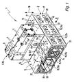
- valve device is designed as a valve manifold and includes a valve carrier 2, which is simultaneously with a plurality of Control units 3 can be equipped, each containing at least one, preferably electrically actuated, control valve 4.
- the control valves 4 include a main valve member 5 equipped with a movable valve member, not shown, and at least one driving member 6 associated therewith.
- the driving member 6 can be electrically activated and causes the respective desired switching state of the main valve member 5.
- a directly controlled control valve 4 in particular an electromagnet and in the case of a pilot-operated control valve 4 to an electrically actuated pilot valve, in particular a solenoid valve.
- the drive part 6 may include a plurality of electromagnets and / or pilot valves.
- control valves 4 are, for example, 3/2-way valves as in FIG. 4 or about 5/2-way valves as in the case of FIG. 2 can act.
- the outer surface of the valve carrier 2 forms a preferably flat mounting surface 7, to which the control units 3, preferably releasably, are mountable.
- the assembly area 7 is in this case divided into a plurality of sequential insertion positions 12 in a row direction indicated by a double arrow which can be used for equipping with the control units 3.
- the row direction 8 coincides in particular with the longitudinal axis of the valve carrier 2.
- the control units 3 expediently have an elongated shape. Its longitudinal axis 13 is perpendicular to the Row direction 8. The same applies to the respective elongated placement places 12th
- valve carrier 2 is penetrated by a designated in its entirety by reference numeral 14, composed of a plurality of valve carrier channels 15 valve carrier channel assembly 14.
- Under the valve carrier channels 15 is expediently at least one connectable to an external pressure source P feed channel 15a and at least one with a pressure sink R, S - in particular the atmosphere - connectable discharge channel 15b, 15c.
- two mutually parallel discharge channels 15b, 15c are present, in order to enable optimal fluid removal, especially in the case of control valves 4 with four-way or five-way functionality.
- the feed channel 15a and the discharge channels 15b, 15c extend in the interior of the valve carrier 2 in the row direction 8, each of them discharging to each placement place 12.
- the corresponding channel mouths are identified by reference numerals 15a ', 15b', 15c '.
- valve carrier channels 15 Under the valve carrier channels 15 are also working channels 15d, 15e. While the feed channels 15a, 15b, 15c are assigned to all placement locations 12 in common, ie one can speak of a common feed channel 15a and common discharge channels 15b, 15c, the working channels 15d, 15e are designed as individual channels, with an individual one for each placement place 12 first working channel 15d and in particular an individual second working channel 15e opens. The associated channel mouths are indicated by reference numerals 15d ', 15e'. These individual working channels 15d, 15e are not interconnected within the valve carrier 2.
- the working channels 15 d, 15 e open via a consumer connection opening 16 enabling a connection of a consumer to a separate external surface of the valve carrier 2 with respect to the assembly surface 7, which is referred to below as the consumer connection surface 17.
- the consumer connection openings 16 are not further shown connection means, to each of which a leading to the consumer fluid line, in particular releasably, can be connected.
- the connection means are, for example, threads or connectors.
- the consumer pad 17 is oriented at right angles to the mounting surface 7.
- the consumer connection openings 16 of the respective same placement space 12 leading working channels 15 d, 15 e are preferably arranged one above the other in the direction indicated by a double arrow height direction 18 of the valve means 1, wherein the height direction 18 is oriented perpendicular to the mounting surface 7.
- the channel mouths 15a '- 15e' form at all placement places 12 matching mouth pattern.
- the orifice patterns may correspond in particular to the standards ISO 5599-2 or ISO 15407.
- valve carrier 2 can in principle be made in one piece, it is in the embodiments in each case of several together in the row direction 8 under sealing seated valve carrier segments 22 together. You can, according to the desired length of the valve carrier 2, be combined with each other in a variable number.
- each valve carrier segment 22 defines two placement places 12 arranged directly next to one another in the row direction 8. In particular, they merge seamlessly into one another.
- Each placement space 12 is in principle suitable for individual placement by means of a control unit 3 which is specifically assigned to it and which for the sake of better distinction is referred to below as the standard control unit 3a.
- the width measured in the row direction 8 of each standard control unit 3a does not exceed the correspondingly measured width of the allocated placement space 12, wherein in particular substantially the same width is present.
- two standard control units 3a can thus be placed on each valve carrier segment 22 in principle at the same time.
- the standard control units 3 a have internal channels (not shown further) which open out to the base area facing the placement space 12 in such a way that, in the installed state, an association-correct connection to the valve carrier channels 15 opening out at the respective placement space 12 takes place.
- the standard control unit 3a may in the simplest case consist of a control valve 4 alone. In FIG. 2 this applies to the standard controller 3a shown on the far right. In another variant of the standard control unit 3a - in FIG. 2 shown second from the right - sits the control valve 4 on a belonging to the standard control unit 3a intermediate plate 23 and is mounted on this at the placement space 2.
- the intermediate plate 23 run between the control valve 4 and this opposite base surface not shown fluid channels that communicate with the channel mouths 15 a '- 15 e' of the associated placement space 12.
- the fluid can undergo any treatment, for example pressure regulation or throttling, for which purpose the intermediate plate 23 can be equipped with fluid influencing means of suitable type (not shown).
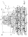
- FIGS. 1 and 2 and on the other hand Figures 3 and 4 In the following, two different types of special control units 3b are explained, wherein the statements always apply simultaneously to both embodiments, unless stated otherwise in detail.
- the special control unit 3b contains an intermediate plate 24 which carries at least one control valve 4. As far as an intermediate plate is generally referred to below, that means a special control unit 3b. If a reference to the intermediate plate 23 of a standard control unit 3a is intended, this is explicitly mentioned.
- the intermediate plate 24 is attached with its bottom 25 ahead of the mounting surface 7, wherein it covers two immediately adjacent placement locations 12 of the assembly surface 7 due to their correspondingly large width.
- Their measured width in the row direction 8 corresponds to twice the width of a placement space 12, wherein it should be noted that in the embodiment all placement slots 12 have the same dimensions.
- each placement place also has a rectangular outline.
- the intermediate plate 24 may also cover more than two placement slots 12 with correspondingly greater width.
- At least one control valve 4 could in principle be mounted on the front side of the preferably parallelepiped-shaped intermediate plate 24 be. However, the design shown is preferred with at least one control valve 4 installed on the upper side 26 of the intermediate plate 24 opposite the valve carrier 2.
- the intermediate plate 24 is equipped with two control valves 4. These sit, in the row direction 8 next to each other, at two correspondingly juxtaposed valve mounting stations 27 of the intermediate plate 24th
- the special control unit 3b is equipped at the top 26 of its intermediate plate 24 with only one valve mounting station 27, which is equipped with the single control valve 4 of this special control unit 3b.
- each special control unit 3b is penetrated by an intermediate plate channel arrangement, generally designated by reference numeral 28, which is composed of a plurality of suitably extending intermediate plate channels 32. With some of the intermediate plate channels 32, the intermediate plate channel arrangement 28 discharges distributed on the underside 25 of the intermediate plate 24 such that different channel connections are formed with the valve carrier channels 12 opening out at the covered placement places 12.
- valve carrier channels 15 and intermediate plate channels 32 can take place in the region of each placement space 12 covered by the intermediate plate 24.
- the channel linkage is thus not limited to the width of a single placement space 12, but may extend over a greater width.
- At least some of the intermediate plate channels 32 open (also) to the at least one valve mounting station 27 and are in fluid communication with valve channels 33 of the respective control valve 4 mounted there.
- the valve channels 33 open at the intermediate plate 24 facing the underside of the relevant control valve 4, that an aligned transition to the valve mounting location 27 existing channel mouths of the intermediate plate channels 32 takes place.
- a fluidic circuit designed for a specific application can be realized within a special control unit 3b. Since in this circuit 12 ausmündende valve support channels 15 can be included at several placement locations, can be implemented in a confined space and very complex and sophisticated circuits, without any additional external line connections.
- the special control unit 3b of the embodiment of the Figures 3 and 4 characterized in that the intermediate plate channel assembly 28 includes two intermediate plate channels 32, which are each formed as a connecting channel 32a, 32b, which opens at different locations on the bottom 25 so that it connects two opening at different of the covered placement places 12 valve carrier channels 15 together.
- a first one (32a) of these two connection channels communicates in particular with two first working channels 15d opening out to different placement places 12 and is otherwise connected to the single control valve 4 via another intermediate plate channel 32c in such a way that it, with the appropriate switching position, uses pressure medium from the first common supply channel 15a can be supplied. In this way, it is possible to supply a consumer connected at the same time to the consumer connection openings 16 of both first working channels 15d with a higher flow rate or to simultaneously apply different consumers simultaneously to the pressure medium.
- a second connection channel 32b can open out at the underside 25 so that it communicates with the feed channel 15a both times at different placement locations 12.
- Another intermediate plate channel 32d connects the second connection channel 32b to the control valve 4.
- An intermediate plate channel 32 designed as a return channel 32e extends between the valve mounting location 27 and the underside 25 and connects the control valve 4 to a discharge channel 15b. In this way, the fluid recycling can take place from each connected consumer when the control valve 4 assumes the illustrated closed position.
- first or second connection channel 32a, 32b could also be dispensed with.
- the intermediate plate 24 is equipped with at least one vacuum generating device 34, which is supplied via the control valve 4 with compressed air, can be connected to the corresponding first and / or second working channels 15b, 15e, a negative pressure can be tapped.
- a negative pressure can be tapped.
- two working channels 15d can be connected to one and the same vacuum generator device 34 at the same time.
- the vacuum generating device 34 operates in particular according to the Ejektorkar and includes a suction nozzle, which causes a negative pressure when it is flowed through by compressed air.
- a particularly good performance can be achieved if two vacuum generator devices 34 are simultaneously operated via a single control valve 4, wherein at the same time a vacuum delivery is possible over two loading stations 12 away.
- FIGS. 1 and 2 run within the intermediate plate 24, two connecting channels 32a ', 32b', each of which one end to the one and the other end to the other valve mounting space 27 and thereby connect both control valves 4 together.
- a return channel 32e 'of the intermediate plate channel assembly 28 connects one of the control valves 4 to a common discharge channel 15b of the valve carrier 2.
- Via a further return channel 32e " two ports of the other control valve 4 are also connected to a common discharge channel 15c a control valve 4 with the common feed channel 15a.
- Working channels 15 d of the valve carrier 2 independently connected via one of the intermediate plate 24 passing through passage 32 g 'to one of the two control valves 4.
- control valves 4 are preferably of the electrically actuated type, the transmission of the electrical control signals provided for them is recommended by means of an electrical signal transmission device 35 running inside the valve carrier 2. The same is only indicated schematically in the drawing and extends in particular in a valve carrier 2 Signaling means 36 passing through in the row direction 8 provide an electrical interface connected to the signal transmission means 35, the electrical conductors passing through the attached intermediate plate 23, 34 with the drive part 6 of the at least one control valve 4 carried by the intermediate plate 23,24 connected is. In a standard control unit 3a without intermediate plate 23, the drive parts 6 can be connected directly to the electrical interface. At 37 are in the field of placement places 12 provided openings of the valve support 2 can be seen, through which the electrical connection between the signal transmission device 35 and the respective associated control unit 3 can take place.
- the electrical control signals could also be supplied without using the valve carrier 2, e.g. via individual cables.
- the exemplary valve device allows a modular expansion.
- the electrical connections as well as the fluidic connections can be made via the valve carrier 2.
- a special control unit 3b quasi at least two otherwise usable for individual assembly with standard control units 3a placement locations 12 summarized in the manner of a height chaining, without having to resort to external hose connections.
- the valve device can be conventionally equipped, in particular it requires no modifications to the possibly used standard control units 3a.
- the intermediate plate channel assembly 28 does not necessarily have all of those of the intermediate plate 24 of the Special control unit 3b covered placements 12 out of leaking valve carrier channels 15 to communicate.
- the mouths of unneeded valve support channels 15 can be easily covered by the intermediate plate 24, as shown in FIG. 4 indicated at 38.
- a seal to be arranged between the intermediate plate 24 and the mounting surface 7 can provide a seal which is also responsible for a leakage-free passage of fluid between the valve carrier channels 15 and intermediate plate channels 32 communicating with one another.
- This seal, in particular plate-shaped and / or formed on the bottom 25 is not shown in the drawing.
Landscapes
- Engineering & Computer Science (AREA)
- Physics & Mathematics (AREA)
- Fluid Mechanics (AREA)
- Mechanical Engineering (AREA)
- General Engineering & Computer Science (AREA)
- Valve Housings (AREA)
- Fluid-Pressure Circuits (AREA)
- Fluid-Driven Valves (AREA)
- Polarising Elements (AREA)
- Details Of Valves (AREA)
Claims (17)
- Ensemble de soupape avec un porte-soupape (2) qui présente une surface de composants (7) qui est divisée en plusieurs emplacements de composant (12) se succédant dans un sens linéaire (8), vers lesquels débouchent respectivement plusieurs canaux de porte-soupape (15) d'un ensemble de canal de porte-soupape (14) traversant le porte-soupape (2) et qui peuvent être équipés individuellement d'unités de commande (3) présentant respectivement au moins une soupape de commande (4), caractérisé en ce que la surface de composants (7) est équipée d'au moins une unité de commande spéciale (3b) qui présente une plaque intermédiaire (24) fixée avec son dessous (25) sur la surface de composants (7) et recouvrant en raison de la largeur correspondante plusieurs emplacements de composant (12) se trouvant directement les uns à côté des autres, qui est traversée par un ensemble de canal de plaque intermédiaire (28) relié sur les emplacements de composant (12) recouverts par celui-ci à l'ensemble de canal de porte-soupape (14) et qui porte au moins une soupape de commande (4) raccordé à l'ensemble de canal de plaque intermédiaire (28).
- Ensemble de soupape selon la revendication 1, caractérisé en ce que l'ensemble de canal de plaque intermédiaire (28) comporte au moins un canal de liaison (32a', 32b') qui relie au moins deux soupapes de commande (4) de l'unité de commande spéciale (3b) l'une à l'autre.
- Ensemble de soupape selon la revendication 1 ou 2, caractérisé en ce que l'ensemble de canal de plaque intermédiaire (28) comporte au moins un canal de liaison (32a, 32b) qui relie au moins deux canaux de porte-soupape (15) débouchant sur différents emplacements de composant (12).
- Ensemble de soupape selon l'une quelconque des revendications 1 à 3, caractérisé en ce qu'un canal de travail (15d, 15e) individuel pouvant être relié à un récepteur de l'ensemble de canal de porte-soupape (14) débouche vers chaque emplacement de composant (12) recouvert par la plaque intermédiaire (34).
- Ensemble de soupape selon l'une quelconque des revendications 1 à 4, caractérisé en ce que vers chaque emplacement de composant (12) débouche au moins un canal de travail (15d, 15e) individuel de l'ensemble de canal de porte-soupape (14) qui débouche au niveau de l'autre extrémité via l'ouverture de raccordement de récepteur (16) permettant le raccordement d'un récepteur vers une surface extérieure du porte-soupape (2) disposée à l'écart de la surface de composants (7).
- Ensemble de soupape selon la revendication 4 ou 5, caractérisé en ce qu'un canal de liaison (32a) de la plaque intermédiaire (24) relie l'un à l'autre au moins deux canaux de travail (12d) débouchant vers des emplacements différents des emplacements de composant (12) recouverts.
- Ensemble de soupape selon l'une quelconque des revendications 1 à 6, caractérisé en ce qu'un canal de porte-soupape (15) est réalisé comme un canal d'alimentation (15a) commun débouchant vers tous les emplacements de composant (12), servant à l'alimentation fluidique commune de tous les emplacements de composant (12).
- Ensemble de soupape selon la revendication 7, caractérisé en ce qu'un canal de liaison (32b) de la plaque intermédiaire (24) est relié sur au moins deux emplacements différents des emplacements de composant (12) recouverts au canal d'alimentation (15a) commun.
- Ensemble de soupape selon l'une quelconque des revendications 1 à 8, caractérisé en ce que la plaque intermédiaire (24) est équipée d'une seule ou de deux soupapes de commande (4).
- Ensemble de soupape selon la revendication 9, caractérisé en ce qu'au moins un canal de liaison (32a', 32b') de l'ensemble de canal de plaque intermédiaire (28) relie deux soupapes de commande (4) l'une à l'autre.
- Ensemble de soupape selon l'une quelconque des revendications 1 à 10, caractérisé en ce que l'au moins une soupape de commande (4) est disposée sur le dessus (26) opposé au porte-soupape (2) de la plaque intermédiaire (24).
- Ensemble de soupape selon l'une quelconque des revendications 1 à 11, caractérisé en ce que la plaque intermédiaire (24) recouvre précisément deux emplacements de composant (12) situés l'un à côté de l'autre.
- Ensemble de soupape selon l'une quelconque des revendications 1 à 12, caractérisé en ce que plusieurs unités de commande spéciales (3b) sont disposées sur la surface de composants (7).
- Ensemble de soupape selon l'une quelconque des revendications 1 à 13, caractérisé en ce qu'au moins une unité de commande spéciale (3b) et au moins une unité de commande (3a) recouvrant une seule surface de composants (12) sont disposées en même temps sur la surface de composants (7).
- Ensemble de soupape selon l'une quelconque des revendications 1 à 14, caractérisé en ce que la plaque intermédiaire (24) est équipée d'au moins un dispositif de génération du vide (34) pouvant être commandé par au moins une soupape de commande (4) portée par la plaque intermédiaire (24).
- Ensemble de soupape selon l'une quelconque des revendications 1 à 15, caractérisé en ce que l'au moins une soupape de commande (4) est du type actionnable électriquement.
- Ensemble de soupape selon l'une quelconque des revendications 1 à 16, caractérisé en ce que le porte-soupape (2) est composé de plusieurs segments de porte-soupape (22) fixés les uns sur les autres dans le sens linéaire (8) qui définissent chacun au moins l'un des emplacements de composant (12).
Applications Claiming Priority (2)
| Application Number | Priority Date | Filing Date | Title |
|---|---|---|---|
| DE102006056089A DE102006056089A1 (de) | 2006-11-28 | 2006-11-28 | Ventileinrichtung |
| PCT/EP2007/009421 WO2008064755A1 (fr) | 2006-11-28 | 2007-10-30 | Ensemble de soupape |
Publications (2)
| Publication Number | Publication Date |
|---|---|
| EP2047112A1 EP2047112A1 (fr) | 2009-04-15 |
| EP2047112B1 true EP2047112B1 (fr) | 2010-05-12 |
Family
ID=38988322
Family Applications (1)
| Application Number | Title | Priority Date | Filing Date |
|---|---|---|---|
| EP20070846520 Active EP2047112B1 (fr) | 2006-11-28 | 2007-10-30 | Ensemble de soupape |
Country Status (6)
| Country | Link |
|---|---|
| US (1) | US8082943B2 (fr) |
| EP (1) | EP2047112B1 (fr) |
| CN (1) | CN101542135B (fr) |
| AT (1) | ATE467770T1 (fr) |
| DE (2) | DE102006056089A1 (fr) |
| WO (1) | WO2008064755A1 (fr) |
Families Citing this family (22)
| Publication number | Priority date | Publication date | Assignee | Title |
|---|---|---|---|---|
| FR2901851B1 (fr) * | 2006-06-02 | 2010-11-19 | Parker Hannifin France Holding | Ilot pour distibuteurs pneumatiques |
| US8413679B2 (en) * | 2008-04-15 | 2013-04-09 | Festo Ag & Co. Kg | Modular control device, especially of an electro-fluidic type |
| JP5576991B2 (ja) * | 2011-09-30 | 2014-08-20 | 株式会社フジキン | ガス供給装置 |
| US10180191B2 (en) * | 2014-06-20 | 2019-01-15 | Asco, L.P. | Zoned manifold assembly for solenoid valve control system |
| DE202015000540U1 (de) | 2015-01-27 | 2015-04-10 | Kendrion Kuhnke Automotive GmbH | Pneumatische Steuer- und Messvorrichtung sowie Sitzkomfortsystem |
| DE202016100111U1 (de) * | 2016-01-13 | 2017-04-20 | J. Schmalz Gmbh | Anlage zur Handhabung von Werkstücken |
| US10092931B2 (en) * | 2016-04-19 | 2018-10-09 | Lamb Weston, Inc. | Food article defect removal apparatus |
| US10052663B2 (en) * | 2016-04-19 | 2018-08-21 | Lamb Weston, Inc. | Food article defect removal apparatus |
| US10753507B2 (en) | 2016-04-19 | 2020-08-25 | Lamb Weston, Inc. | Food article defect removal apparatus |
| US11493275B2 (en) | 2017-10-10 | 2022-11-08 | Tps Ip, Llc | Oven with renewable energy capacities |
| US11299925B2 (en) | 2017-10-11 | 2022-04-12 | Tps Ip, Llc | Oven with split doors |
| US11585701B2 (en) | 2017-10-27 | 2023-02-21 | Tps Ip, Llc | Intelligent oven |
| US10794508B2 (en) * | 2017-11-14 | 2020-10-06 | Tps Ip, Llc | Atmosphere control manifold |
| US10798947B2 (en) | 2017-12-08 | 2020-10-13 | Tps Ip, Llc | Oven with augmented reality functionality |
| US10731677B2 (en) * | 2017-12-27 | 2020-08-04 | Mac Valves, Inc. | Pneumatic control valve manifold |
| US11346560B2 (en) | 2017-12-29 | 2022-05-31 | Tps Ip, Llc | Oven wall compositions and/or structures |
| DE102018215218B4 (de) * | 2018-09-07 | 2025-07-31 | Festo Se & Co. Kg | Fluidmodulanordnung |
| JP6975749B2 (ja) * | 2019-05-15 | 2021-12-01 | Ckd株式会社 | パイロット形電磁弁 |
| DE102019208495A1 (de) * | 2019-06-12 | 2020-12-17 | Sms Group Gmbh | Hydraulische Steuereinrichtung im Walzwerksbau |
| DE102020202577B4 (de) * | 2020-02-28 | 2022-09-15 | Festo Se & Co. Kg | Ventilmodul, Ventilanordnung und Verfahren |
| CN111745673A (zh) * | 2020-07-09 | 2020-10-09 | 伯朗特机器人股份有限公司 | 一种用于工业机器人夹具的通用气动控制机构 |
| FR3149937A1 (fr) * | 2023-06-13 | 2024-12-20 | Robert Bosch Gmbh | Installation hydraulique à distributeurs découplés |
Family Cites Families (15)
| Publication number | Priority date | Publication date | Assignee | Title |
|---|---|---|---|---|
| US3213883A (en) * | 1962-09-13 | 1965-10-26 | Carls William | Two-piece multiple valve manifold |
| JPS5325775A (en) | 1976-08-24 | 1978-03-09 | Miller Fluid Power Corp | Module type fluid flow control element |
| DE4226539A1 (de) * | 1992-08-11 | 1994-02-17 | Bosch Gmbh Robert | Elektropneumatische Ventilbaugruppe |
| DE4444024A1 (de) * | 1994-12-10 | 1996-06-13 | Festo Kg | Steuereinrichtung, insbesondere zur Ansteuerung von Ventilen |
| US6053198A (en) * | 1997-12-01 | 2000-04-25 | Numatics, Incorporated | Solenoid valve control system |
| DE29810091U1 (de) * | 1998-06-05 | 1998-12-10 | Airtec Pneumatic GmbH, 72829 Engstingen | Ventilterminal mit einer Reihe von Schaltventilen |
| FR2807793B1 (fr) * | 2000-04-17 | 2002-05-31 | Parker Hannifin Rak Sa | Module d'interface pour ilot de distributeurs electropneumatiques |
| JP3825288B2 (ja) | 2001-08-13 | 2006-09-27 | Smc株式会社 | 電磁弁用マニホールド |
| FR2829194B1 (fr) * | 2001-09-05 | 2004-11-19 | Parker Hannifin Rak Sa | Ilot de modules pneumatiques |
| DE10213397B4 (de) | 2002-03-26 | 2005-04-14 | Festo Ag & Co. | Ventilanordnung |
| GB0217709D0 (en) | 2002-07-31 | 2002-09-11 | Koninkl Philips Electronics Nv | Array device with switching circuits |
| DE10347936B4 (de) * | 2003-10-15 | 2007-09-27 | Bosch Rexroth Pneumatics Gmbh | Ventilanordnung mit einstellbarer Funktion und Verfahren hierfür |
| DE102004046547A1 (de) * | 2004-09-20 | 2006-04-06 | Festo Ag & Co. | Fluidtechnisches Gerät mit Druckregler |
| JP4919002B2 (ja) * | 2005-06-20 | 2012-04-18 | Smc株式会社 | マニホールド形電磁弁集合体 |
| DE202006008921U1 (de) | 2006-06-07 | 2006-08-10 | Festo Ag & Co. | Ventilanordnung |
-
2006
- 2006-11-28 DE DE102006056089A patent/DE102006056089A1/de not_active Withdrawn
-
2007
- 2007-10-30 US US12/310,866 patent/US8082943B2/en not_active Expired - Fee Related
- 2007-10-30 DE DE200750003771 patent/DE502007003771D1/de active Active
- 2007-10-30 WO PCT/EP2007/009421 patent/WO2008064755A1/fr not_active Ceased
- 2007-10-30 EP EP20070846520 patent/EP2047112B1/fr active Active
- 2007-10-30 CN CN2007800443629A patent/CN101542135B/zh not_active Expired - Fee Related
- 2007-10-30 AT AT07846520T patent/ATE467770T1/de active
Also Published As
| Publication number | Publication date |
|---|---|
| CN101542135B (zh) | 2012-02-08 |
| DE102006056089A1 (de) | 2008-05-29 |
| WO2008064755A1 (fr) | 2008-06-05 |
| ATE467770T1 (de) | 2010-05-15 |
| DE502007003771D1 (de) | 2010-06-24 |
| EP2047112A1 (fr) | 2009-04-15 |
| US8082943B2 (en) | 2011-12-27 |
| CN101542135A (zh) | 2009-09-23 |
| US20090205724A1 (en) | 2009-08-20 |
Similar Documents
| Publication | Publication Date | Title |
|---|---|---|
| EP2047112B1 (fr) | Ensemble de soupape | |
| DE60301746T2 (de) | Pneumatikventilgruppe mit einfacher Installierung und einfacher Wartung | |
| EP1013940B1 (fr) | Arrangement de soupape | |
| DE19711227C2 (de) | Ventilanordnung | |
| EP2024648B1 (fr) | Agencement de soupape | |
| WO2008138371A1 (fr) | Agencement de soupapes modulaire pour des catégories de débit différentes | |
| WO1994004831A1 (fr) | Dispositif de commande electropneumatique | |
| EP3296602B1 (fr) | Dispositif de distribution de fluide | |
| EP1041325B1 (fr) | Assemblage de soupapes | |
| DE9211109U1 (de) | Elektro-pneumatische Steuereinrichtung | |
| EP1991791B1 (fr) | Batterie de distributeurs à distributeur de sécurité | |
| DE10213397B4 (de) | Ventilanordnung | |
| DE4312729A1 (de) | Ventilstation | |
| DE10153545B4 (de) | Fluidkraft-Verriegelungssystem und Verfahren zum Verriegeln von Fluidkraftsignalen | |
| EP2674652B1 (fr) | Agencement de soupape avec vannes à manchon | |
| EP1251283B1 (fr) | Kit pour fabriquer un dispositif de contrôle fluidique | |
| EP2514977A2 (fr) | Bloc de presse | |
| WO2011038813A1 (fr) | Bloc de distribution haute pression d'une unité d'alimentation en lubrifiant-réfrigérant | |
| EP2530334A1 (fr) | Agencement de vannes | |
| EP2770216B1 (fr) | Agencement de vannes | |
| EP2110563B1 (fr) | Agencement de soupape doté d'un dispositif de fermeture central | |
| DE19909920A1 (de) | Sicherheitsschaltung für einen pneumatischen Motor | |
| EP1182358B1 (fr) | Unité de configuration | |
| WO2002012730A2 (fr) | Bloc a soupapes pour une machine a former le verre | |
| DE2845922A1 (de) | Vorgesteuertes wegeventil mit verteilerfunktion |
Legal Events
| Date | Code | Title | Description |
|---|---|---|---|
| PUAI | Public reference made under article 153(3) epc to a published international application that has entered the european phase |
Free format text: ORIGINAL CODE: 0009012 |
|
| 17P | Request for examination filed |
Effective date: 20081202 |
|
| AK | Designated contracting states |
Kind code of ref document: A1 Designated state(s): AT BE BG CH CY CZ DE DK EE ES FI FR GB GR HU IE IS IT LI LT LU LV MC MT NL PL PT RO SE SI SK TR |
|
| AX | Request for extension of the european patent |
Extension state: AL BA HR MK RS |
|
| GRAP | Despatch of communication of intention to grant a patent |
Free format text: ORIGINAL CODE: EPIDOSNIGR1 |
|
| GRAC | Information related to communication of intention to grant a patent modified |
Free format text: ORIGINAL CODE: EPIDOSCIGR1 |
|
| DAX | Request for extension of the european patent (deleted) | ||
| GRAS | Grant fee paid |
Free format text: ORIGINAL CODE: EPIDOSNIGR3 |
|
| GRAA | (expected) grant |
Free format text: ORIGINAL CODE: 0009210 |
|
| AK | Designated contracting states |
Kind code of ref document: B1 Designated state(s): AT BE BG CH CY CZ DE DK EE ES FI FR GB GR HU IE IS IT LI LT LU LV MC MT NL PL PT RO SE SI SK TR |
|
| REG | Reference to a national code |
Ref country code: GB Ref legal event code: FG4D Free format text: NOT ENGLISH |
|
| REG | Reference to a national code |
Ref country code: CH Ref legal event code: EP |
|
| REG | Reference to a national code |
Ref country code: IE Ref legal event code: FG4D Free format text: LANGUAGE OF EP DOCUMENT: GERMAN |
|
| REF | Corresponds to: |
Ref document number: 502007003771 Country of ref document: DE Date of ref document: 20100624 Kind code of ref document: P |
|
| REG | Reference to a national code |
Ref country code: NL Ref legal event code: VDEP Effective date: 20100512 |
|
| LTIE | Lt: invalidation of european patent or patent extension |
Effective date: 20100512 |
|
| PG25 | Lapsed in a contracting state [announced via postgrant information from national office to epo] |
Ref country code: ES Free format text: LAPSE BECAUSE OF FAILURE TO SUBMIT A TRANSLATION OF THE DESCRIPTION OR TO PAY THE FEE WITHIN THE PRESCRIBED TIME-LIMIT Effective date: 20100823 Ref country code: LT Free format text: LAPSE BECAUSE OF FAILURE TO SUBMIT A TRANSLATION OF THE DESCRIPTION OR TO PAY THE FEE WITHIN THE PRESCRIBED TIME-LIMIT Effective date: 20100512 Ref country code: NL Free format text: LAPSE BECAUSE OF FAILURE TO SUBMIT A TRANSLATION OF THE DESCRIPTION OR TO PAY THE FEE WITHIN THE PRESCRIBED TIME-LIMIT Effective date: 20100512 Ref country code: SE Free format text: LAPSE BECAUSE OF FAILURE TO SUBMIT A TRANSLATION OF THE DESCRIPTION OR TO PAY THE FEE WITHIN THE PRESCRIBED TIME-LIMIT Effective date: 20100512 |
|
| PG25 | Lapsed in a contracting state [announced via postgrant information from national office to epo] |
Ref country code: SI Free format text: LAPSE BECAUSE OF FAILURE TO SUBMIT A TRANSLATION OF THE DESCRIPTION OR TO PAY THE FEE WITHIN THE PRESCRIBED TIME-LIMIT Effective date: 20100512 Ref country code: LV Free format text: LAPSE BECAUSE OF FAILURE TO SUBMIT A TRANSLATION OF THE DESCRIPTION OR TO PAY THE FEE WITHIN THE PRESCRIBED TIME-LIMIT Effective date: 20100512 Ref country code: IS Free format text: LAPSE BECAUSE OF FAILURE TO SUBMIT A TRANSLATION OF THE DESCRIPTION OR TO PAY THE FEE WITHIN THE PRESCRIBED TIME-LIMIT Effective date: 20100912 Ref country code: FI Free format text: LAPSE BECAUSE OF FAILURE TO SUBMIT A TRANSLATION OF THE DESCRIPTION OR TO PAY THE FEE WITHIN THE PRESCRIBED TIME-LIMIT Effective date: 20100512 |
|
| REG | Reference to a national code |
Ref country code: IE Ref legal event code: FD4D |
|
| PG25 | Lapsed in a contracting state [announced via postgrant information from national office to epo] |
Ref country code: CY Free format text: LAPSE BECAUSE OF FAILURE TO SUBMIT A TRANSLATION OF THE DESCRIPTION OR TO PAY THE FEE WITHIN THE PRESCRIBED TIME-LIMIT Effective date: 20100609 Ref country code: PL Free format text: LAPSE BECAUSE OF FAILURE TO SUBMIT A TRANSLATION OF THE DESCRIPTION OR TO PAY THE FEE WITHIN THE PRESCRIBED TIME-LIMIT Effective date: 20100512 |
|
| PG25 | Lapsed in a contracting state [announced via postgrant information from national office to epo] |
Ref country code: EE Free format text: LAPSE BECAUSE OF FAILURE TO SUBMIT A TRANSLATION OF THE DESCRIPTION OR TO PAY THE FEE WITHIN THE PRESCRIBED TIME-LIMIT Effective date: 20100512 Ref country code: DK Free format text: LAPSE BECAUSE OF FAILURE TO SUBMIT A TRANSLATION OF THE DESCRIPTION OR TO PAY THE FEE WITHIN THE PRESCRIBED TIME-LIMIT Effective date: 20100512 Ref country code: IE Free format text: LAPSE BECAUSE OF FAILURE TO SUBMIT A TRANSLATION OF THE DESCRIPTION OR TO PAY THE FEE WITHIN THE PRESCRIBED TIME-LIMIT Effective date: 20100512 Ref country code: PT Free format text: LAPSE BECAUSE OF FAILURE TO SUBMIT A TRANSLATION OF THE DESCRIPTION OR TO PAY THE FEE WITHIN THE PRESCRIBED TIME-LIMIT Effective date: 20100913 |
|
| PG25 | Lapsed in a contracting state [announced via postgrant information from national office to epo] |
Ref country code: RO Free format text: LAPSE BECAUSE OF FAILURE TO SUBMIT A TRANSLATION OF THE DESCRIPTION OR TO PAY THE FEE WITHIN THE PRESCRIBED TIME-LIMIT Effective date: 20100512 Ref country code: CZ Free format text: LAPSE BECAUSE OF FAILURE TO SUBMIT A TRANSLATION OF THE DESCRIPTION OR TO PAY THE FEE WITHIN THE PRESCRIBED TIME-LIMIT Effective date: 20100512 Ref country code: SK Free format text: LAPSE BECAUSE OF FAILURE TO SUBMIT A TRANSLATION OF THE DESCRIPTION OR TO PAY THE FEE WITHIN THE PRESCRIBED TIME-LIMIT Effective date: 20100512 |
|
| PLBE | No opposition filed within time limit |
Free format text: ORIGINAL CODE: 0009261 |
|
| STAA | Information on the status of an ep patent application or granted ep patent |
Free format text: STATUS: NO OPPOSITION FILED WITHIN TIME LIMIT |
|
| 26N | No opposition filed |
Effective date: 20110215 |
|
| BERE | Be: lapsed |
Owner name: FESTO A.G. & CO. KG Effective date: 20101031 |
|
| PG25 | Lapsed in a contracting state [announced via postgrant information from national office to epo] |
Ref country code: MC Free format text: LAPSE BECAUSE OF NON-PAYMENT OF DUE FEES Effective date: 20101031 Ref country code: GR Free format text: LAPSE BECAUSE OF FAILURE TO SUBMIT A TRANSLATION OF THE DESCRIPTION OR TO PAY THE FEE WITHIN THE PRESCRIBED TIME-LIMIT Effective date: 20100813 |
|
| REG | Reference to a national code |
Ref country code: DE Ref legal event code: R097 Ref document number: 502007003771 Country of ref document: DE Effective date: 20110214 |
|
| PG25 | Lapsed in a contracting state [announced via postgrant information from national office to epo] |
Ref country code: BE Free format text: LAPSE BECAUSE OF NON-PAYMENT OF DUE FEES Effective date: 20101031 |
|
| PG25 | Lapsed in a contracting state [announced via postgrant information from national office to epo] |
Ref country code: IT Free format text: LAPSE BECAUSE OF NON-PAYMENT OF DUE FEES Effective date: 20101030 Ref country code: MT Free format text: LAPSE BECAUSE OF FAILURE TO SUBMIT A TRANSLATION OF THE DESCRIPTION OR TO PAY THE FEE WITHIN THE PRESCRIBED TIME-LIMIT Effective date: 20100512 |
|
| REG | Reference to a national code |
Ref country code: CH Ref legal event code: PL |
|
| PG25 | Lapsed in a contracting state [announced via postgrant information from national office to epo] |
Ref country code: LI Free format text: LAPSE BECAUSE OF NON-PAYMENT OF DUE FEES Effective date: 20111031 Ref country code: CH Free format text: LAPSE BECAUSE OF NON-PAYMENT OF DUE FEES Effective date: 20111031 |
|
| PG25 | Lapsed in a contracting state [announced via postgrant information from national office to epo] |
Ref country code: BG Free format text: LAPSE BECAUSE OF FAILURE TO SUBMIT A TRANSLATION OF THE DESCRIPTION OR TO PAY THE FEE WITHIN THE PRESCRIBED TIME-LIMIT Effective date: 20100512 Ref country code: HU Free format text: LAPSE BECAUSE OF FAILURE TO SUBMIT A TRANSLATION OF THE DESCRIPTION OR TO PAY THE FEE WITHIN THE PRESCRIBED TIME-LIMIT Effective date: 20101113 Ref country code: LU Free format text: LAPSE BECAUSE OF NON-PAYMENT OF DUE FEES Effective date: 20101030 |
|
| PG25 | Lapsed in a contracting state [announced via postgrant information from national office to epo] |
Ref country code: TR Free format text: LAPSE BECAUSE OF FAILURE TO SUBMIT A TRANSLATION OF THE DESCRIPTION OR TO PAY THE FEE WITHIN THE PRESCRIBED TIME-LIMIT Effective date: 20100512 |
|
| PG25 | Lapsed in a contracting state [announced via postgrant information from national office to epo] |
Ref country code: BG Free format text: LAPSE BECAUSE OF FAILURE TO SUBMIT A TRANSLATION OF THE DESCRIPTION OR TO PAY THE FEE WITHIN THE PRESCRIBED TIME-LIMIT Effective date: 20100812 |
|
| REG | Reference to a national code |
Ref country code: AT Ref legal event code: MM01 Ref document number: 467770 Country of ref document: AT Kind code of ref document: T Effective date: 20121031 |
|
| PG25 | Lapsed in a contracting state [announced via postgrant information from national office to epo] |
Ref country code: AT Free format text: LAPSE BECAUSE OF NON-PAYMENT OF DUE FEES Effective date: 20121031 |
|
| REG | Reference to a national code |
Ref country code: FR Ref legal event code: PLFP Year of fee payment: 9 |
|
| REG | Reference to a national code |
Ref country code: FR Ref legal event code: PLFP Year of fee payment: 10 |
|
| PGFP | Annual fee paid to national office [announced via postgrant information from national office to epo] |
Ref country code: GB Payment date: 20160923 Year of fee payment: 10 |
|
| REG | Reference to a national code |
Ref country code: FR Ref legal event code: PLFP Year of fee payment: 11 |
|
| PGFP | Annual fee paid to national office [announced via postgrant information from national office to epo] |
Ref country code: FR Payment date: 20171023 Year of fee payment: 11 |
|
| PGFP | Annual fee paid to national office [announced via postgrant information from national office to epo] |
Ref country code: IT Payment date: 20171020 Year of fee payment: 11 |
|
| GBPC | Gb: european patent ceased through non-payment of renewal fee |
Effective date: 20171030 |
|
| PG25 | Lapsed in a contracting state [announced via postgrant information from national office to epo] |
Ref country code: GB Free format text: LAPSE BECAUSE OF NON-PAYMENT OF DUE FEES Effective date: 20171030 |
|
| PG25 | Lapsed in a contracting state [announced via postgrant information from national office to epo] |
Ref country code: FR Free format text: LAPSE BECAUSE OF NON-PAYMENT OF DUE FEES Effective date: 20181031 |
|
| PG25 | Lapsed in a contracting state [announced via postgrant information from national office to epo] |
Ref country code: IT Free format text: LAPSE BECAUSE OF NON-PAYMENT OF DUE FEES Effective date: 20181030 |
|
| REG | Reference to a national code |
Ref country code: DE Ref legal event code: R082 Ref document number: 502007003771 Country of ref document: DE Representative=s name: PATENTANWAELTE MAGENBAUER & KOLLEGEN PARTNERSC, DE Ref country code: DE Ref legal event code: R081 Ref document number: 502007003771 Country of ref document: DE Owner name: FESTO SE & CO. KG, DE Free format text: FORMER OWNER: FESTO AG & CO. KG, 73734 ESSLINGEN, DE Ref country code: DE Ref legal event code: R081 Ref document number: 502007003771 Country of ref document: DE Owner name: FESTO AG & CO. KG, DE Free format text: FORMER OWNER: FESTO AG & CO. KG, 73734 ESSLINGEN, DE |
|
| PGFP | Annual fee paid to national office [announced via postgrant information from national office to epo] |
Ref country code: DE Payment date: 20240917 Year of fee payment: 18 |