EP2047166B1 - Metall-metall-dichtung für bohrlochwerkzeuge - Google Patents
Metall-metall-dichtung für bohrlochwerkzeuge Download PDFInfo
- Publication number
- EP2047166B1 EP2047166B1 EP06813289.3A EP06813289A EP2047166B1 EP 2047166 B1 EP2047166 B1 EP 2047166B1 EP 06813289 A EP06813289 A EP 06813289A EP 2047166 B1 EP2047166 B1 EP 2047166B1
- Authority
- EP
- European Patent Office
- Prior art keywords
- closure member
- seal
- metal seal
- metal
- housing assembly
- Prior art date
- Legal status (The legal status is an assumption and is not a legal conclusion. Google has not performed a legal analysis and makes no representation as to the accuracy of the status listed.)
- Not-in-force
Links
- 239000002184 metal Substances 0.000 title claims description 76
- 229910052751 metal Inorganic materials 0.000 title claims description 76
- 238000007789 sealing Methods 0.000 claims description 94
- 229910052755 nonmetal Inorganic materials 0.000 claims description 57
- 238000000034 method Methods 0.000 claims description 10
- 230000004044 response Effects 0.000 claims description 4
- 230000007246 mechanism Effects 0.000 description 10
- 230000006835 compression Effects 0.000 description 6
- 238000007906 compression Methods 0.000 description 6
- 230000008901 benefit Effects 0.000 description 4
- 230000005489 elastic deformation Effects 0.000 description 3
- 239000000463 material Substances 0.000 description 3
- 229920001971 elastomer Polymers 0.000 description 2
- 239000000806 elastomer Substances 0.000 description 2
- 239000012530 fluid Substances 0.000 description 2
- 150000002739 metals Chemical class 0.000 description 2
- 229910000669 Chrome steel Inorganic materials 0.000 description 1
- -1 Inconel 718 Chemical class 0.000 description 1
- 229920000459 Nitrile rubber Polymers 0.000 description 1
- 239000004696 Poly ether ether ketone Substances 0.000 description 1
- 238000007792 addition Methods 0.000 description 1
- JUPQTSLXMOCDHR-UHFFFAOYSA-N benzene-1,4-diol;bis(4-fluorophenyl)methanone Chemical compound OC1=CC=C(O)C=C1.C1=CC(F)=CC=C1C(=O)C1=CC=C(F)C=C1 JUPQTSLXMOCDHR-UHFFFAOYSA-N 0.000 description 1
- 238000004891 communication Methods 0.000 description 1
- 239000012141 concentrate Substances 0.000 description 1
- 238000012217 deletion Methods 0.000 description 1
- 230000037430 deletion Effects 0.000 description 1
- 230000001419 dependent effect Effects 0.000 description 1
- 229920001973 fluoroelastomer Polymers 0.000 description 1
- 229920006168 hydrated nitrile rubber Polymers 0.000 description 1
- 229910000816 inconels 718 Inorganic materials 0.000 description 1
- 230000001788 irregular Effects 0.000 description 1
- 238000004519 manufacturing process Methods 0.000 description 1
- 239000007769 metal material Substances 0.000 description 1
- 238000012986 modification Methods 0.000 description 1
- 230000004048 modification Effects 0.000 description 1
- 229920002530 polyetherether ketone Polymers 0.000 description 1
- 239000012858 resilient material Substances 0.000 description 1
- 230000003068 static effect Effects 0.000 description 1
- 238000006467 substitution reaction Methods 0.000 description 1
Images


Classifications
-
- F—MECHANICAL ENGINEERING; LIGHTING; HEATING; WEAPONS; BLASTING
- F16—ENGINEERING ELEMENTS AND UNITS; GENERAL MEASURES FOR PRODUCING AND MAINTAINING EFFECTIVE FUNCTIONING OF MACHINES OR INSTALLATIONS; THERMAL INSULATION IN GENERAL
- F16J—PISTONS; CYLINDERS; SEALINGS
- F16J15/00—Sealings
- F16J15/02—Sealings between relatively-stationary surfaces
- F16J15/06—Sealings between relatively-stationary surfaces with solid packing compressed between sealing surfaces
- F16J15/10—Sealings between relatively-stationary surfaces with solid packing compressed between sealing surfaces with non-metallic packing
- F16J15/12—Sealings between relatively-stationary surfaces with solid packing compressed between sealing surfaces with non-metallic packing with metal reinforcement or covering
- F16J15/121—Sealings between relatively-stationary surfaces with solid packing compressed between sealing surfaces with non-metallic packing with metal reinforcement or covering with metal reinforcement
-
- E—FIXED CONSTRUCTIONS
- E21—EARTH OR ROCK DRILLING; MINING
- E21B—EARTH OR ROCK DRILLING; OBTAINING OIL, GAS, WATER, SOLUBLE OR MELTABLE MATERIALS OR A SLURRY OF MINERALS FROM WELLS
- E21B34/00—Valve arrangements for boreholes or wells
- E21B34/06—Valve arrangements for boreholes or wells in wells
-
- F—MECHANICAL ENGINEERING; LIGHTING; HEATING; WEAPONS; BLASTING
- F16—ENGINEERING ELEMENTS AND UNITS; GENERAL MEASURES FOR PRODUCING AND MAINTAINING EFFECTIVE FUNCTIONING OF MACHINES OR INSTALLATIONS; THERMAL INSULATION IN GENERAL
- F16J—PISTONS; CYLINDERS; SEALINGS
- F16J15/00—Sealings
- F16J15/02—Sealings between relatively-stationary surfaces
- F16J15/06—Sealings between relatively-stationary surfaces with solid packing compressed between sealing surfaces
- F16J15/08—Sealings between relatively-stationary surfaces with solid packing compressed between sealing surfaces with exclusively metal packing
- F16J15/0887—Sealings between relatively-stationary surfaces with solid packing compressed between sealing surfaces with exclusively metal packing the sealing effect being obtained by elastic deformation of the packing
-
- E—FIXED CONSTRUCTIONS
- E21—EARTH OR ROCK DRILLING; MINING
- E21B—EARTH OR ROCK DRILLING; OBTAINING OIL, GAS, WATER, SOLUBLE OR MELTABLE MATERIALS OR A SLURRY OF MINERALS FROM WELLS
- E21B2200/00—Special features related to earth drilling for obtaining oil, gas or water
- E21B2200/06—Sleeve valves
Definitions
- the present invention relates generally to equipment utilized and operations performed in conjunction with a subterranean well and, in an embodiment described herein, more particularly provides a metal seal for downhole tools.
- Metal seals are sometimes used to seal between structures in well tools, and in equipment used in other environments. However, several problems are frequently
- metal seals require very smooth and clean surfaces to seal against, and most metals can only be elastically deformed to a limited extent (which thereby limits the biasing force available from elastically deforming a metal seal), etc.
- Elastomeric and other types of nonmetal seals may provide the ability to seal against irregular and unclean surfaces, and may provide sufficient resilient biasing force for urging the seals against the surfaces.
- nonmetal seals tend to degrade rapidly when used in dynamic configurations, i.e., where the seal must contact a moving surface while sealing against a pressure differential, or where the seal loses contact with the surface while the pressure differential still exists across the seal.
- EP 0 553 997 A2 discloses a well tool and a method of sealing according to claims 1 and 6 respectively.
- a sealing device which solves at least one problem in the art.
- the sealing device includes both a metal seal and an elastomer seal.
- elastomer seals are used to energize metal seals in response to pressure differentials in different directions.
- the sealing device includes at least one metal seal.
- a nonmetal seal may be used to bias the metal seal in a radial direction in response to a pressure differential applied to the sealing device.
- a well tool which includes a housing assembly and a closure member is also described herein.
- a sealing device is used for sealing between the housing assembly and closure member.
- the sealing device includes at least one metal seal and at least one nonmetal seal. Both of the metal and nonmetal seals contact one of the housing assembly and closure member when the closure member blocks flow through the housing assembly.
- a method of sealing between a housing assembly and a closure member includes the steps of: providing a sealing device including at least one metal seal and at least one nonmetal seal; applying a pressure differential across the sealing device while the sealing device seals between the housing assembly and the closure member; and displacing the closure member to relieve the pressure differential.
- the metal seal continues to seal against the pressure differential until the nonmetal seal no longer seals between the housing assembly and the closure member.
- FIG. 1 Representatively illustrated in FIG. 1 is a well system 10 which embodies principles of the present invention.
- a tubular string 12 (such as a production tubing string) is positioned in a wellbore 14 lined with casing 16.
- the tubular string 12 includes well tools 18, 20.
- the well tool 18 is a packer, and the well tool 20 is a flow control device (such as a valve or choke).
- the packer provides an annular seal between the tubular string 12 and the casing 16, and the flow control device regulates fluid communication between the interior of the tubular string and an annulus 22 formed between the tubular string and the casing.
- the flow control device includes a closure mechanism 24 which is operated to regulate flow.
- the invention is not limited to any of the details of the well system 10 described herein.
- the closure mechanism 24 could, as another example, be used in a hydraulic setting device of the packer 18, or could be used in another type of well tool.
- the well system 10 is only a single example of a wide variety of uses for the principles of the invention.
- FIG. 2 an enlarged scale cross-sectional view of a portion of the well tool 20 is representatively illustrated.
- the closure mechanism 24 includes a tubular closure member 26 which is displaced relative to a housing assembly 28 to thereby regulate flow through openings 30 in the housing assembly.
- the closure member 26 engages a sealing device 34.
- the sealing device 34 operates to provide a seal between the closure member 26 and the housing assembly 28 to thereby prevent flow through the openings 30.
- both metal seals 32a, 32b and nonmetal seals 36a, 36b are included in the device. These seals 32a, 32b, 36a, 36b contact and seal against the closure member 26 when the closure member is in the position depicted in FIG. 2 .
- the sealing device 34 could be carried on, and displace with, the closure member 26, so that the seals 32a, 32b, 36a, 36b could contact and seal against the housing assembly 28 when the closure member is in the position depicted in FIG. 2 , if desired.
- seal 38 sealing between the sealing device 34 and the housing assembly 28.
- this seal 38 could be incorporated into the sealing device 34, if desired.
- the nonmetal seals 36a, 36b could extend further radially outward into sealing contact with the housing assembly 28, and/or a seal could be formed by metal to metal contact between the housing assembly and an outer ring 40 of the device 34.
- each of the nonmetal seals 36a, 36b includes a generally wedge-shaped portion 46a, 46b positioned between the ring 40 and a respective one of the arms 42a, 42b.
- the metal seals 32a, 32b are preferably made of strong, durable and resilient metals, such as Inconel 718, 13-chrome steel, etc.
- the nonmetal seals 36a, 36b are preferably made of high temperature and well fluid resistant, strong and elastomeric materials, such as NBR, HNBR, fluoroelastomers, etc. Non-elastomeric materials, such as PEEK, etc., may additionally or alternatively be used in the nonmetal seals 36a, 36b. It should be clearly understood that any metal materials may be used for the metal seals 32a, 32b, and any nonmetal materials may be used for the nonmetal seals 36a, 36b, in keeping with the principles of the invention.
- nonmetal seals 36a, 36b are not necessary for the sealing device 34 to seal between the housing assembly 28 and the closure member 26.
- the sealing device 34 could be provided without the nonmetal seals 36a, 36b, in which case the metal seals 32a, 32b would still provide sealing engagement with the closure member 26.
- Use of the nonmetal seals 36a, 36b is preferred when a bubble-tight sealing engagement is required.
- the seal surfaces 44a, 44b contact the outer surface of the closure member and the arms 42a, 42b are deflected radially outward somewhat. This deflection causes elastic deformation of the arms 42a, 42b, resulting in a biasing force being applied by the arms to the seal surfaces 44a, 44b.
- the seal surfaces 44a, 44b have small ridges formed thereon to concentrate this radial biasing force on a relatively small area, thereby increasing the contact pressure between the seal surfaces and the outer surface of the closure member 26. It should be understood, however, that use of the small ridges is not required on the seal surfaces 44a, 44b.
- the nonmetal seals 36a, 36b are also radially compressed between the ring 40 and the outer surface of the closure member 26. In this manner, a seal surface 48a, 48b on each nonmetal seal 36a, 36b is biased into sealing contact with the outer surface of the closure member 26.
- each of the sealing surfaces 44a, 44b is radially biased into metal to metal sealing contact with the outer surface of the closure member 26 due to: 1) elastic deformation of the respective arm 42a, 42b, 2) compression of the respective wedge portion 46a, 46b between the ring 40 and the respective arm due to deformation of the arm, and 3) compression of the respective wedge portion 46a, 46b due to the pressure differential 50 or 52.
- sealing contact with the closure member is progressively removed from the lower nonmetal seal 36b, then the lower metal seal 32b, then the upper metal seal 32a, and then the upper nonmetal seal 36a.
- closure member 26 When the closure member 26 eventually displaces upward sufficiently far that it no longer is in sealing contact with the upper nonmetal seal 36a, and the pressure differential across this seal is thus relieved, the closure member will still be contained within a closely fitted sleeve 66 in which the openings 30 are formed, thereby preventing damage to the seal from excessive flow.
- the pressure differential 50 or 52 may be applied when the closure member sealingly engages the sealing device 34.
- the pressure differential 50 or 52 will first be applied to the upper nonmetal seal 36a while the closure member 26 remains within the closely fitted sleeve 66, thereby preventing damage to the seal from excessive flow.
- the closure member 26 sealingly contacts the upper metal seal 32a, the lower metal seal 32b, and the lower nonmetal seal 36b.
- the sealing device 34 provides significant benefits in performing the sealing function in the closure mechanism 24 of the well tool 20.
- the metal seals 32a, 32b provide for metal to metal sealing between the closure member 26 and the housing assembly 28, the metal seals are resiliently biased into sealing contact in multiple ways (including an increased biasing force as the differential pressure across the sealing device 34 increases), and the nonmetal seals 36a, 36b provide for additional sealing capability in the event that metal to metal sealing cannot be achieved.
- Pressure differentials from either direction across the sealing device 34 can be sealed against, without damage to the seals 32a, 32b, 36a, 36b, whether the closure member 26 displaces to close or open while the pressure differential exists.
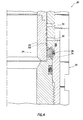
- This alternate configuration of the closure mechanism 24 includes an alternate configuration of the sealing device 34, which is depicted in a further enlarged cross-sectional view in FIG. 5 .
- the sealing device 34 as illustrated in FIG. 5 is similar in some respects to the sealing device of FIG. 3 , in that it includes multiple metal seals 54a, 54b with respective seal surfaces 56a, 56b and inclined beams or arms 58a, 58b extending between the seal surfaces and a ring 60.
- the sealing device 34 of FIG. 5 also includes multiple nonmetal seals 62a, 62b positioned between the metal seals 54a, 54b.
- a wedge portion 64a, 64b of each respective nonmetal seal 62a, 62b is positioned between a respective one of the arms 58a, 58b and the ring 60.
- a difference between the nonmetal seals 62a, 62b and the nonmetal seals 36a, 36b described above is that the seals 62a, 62b are formed as a single, integral element, rather than as separate elements. Indeed the nonmetal seals 62a, 62b could be formed as a single seal, if desired. Furthermore, as discussed above for the nonmetal seals 36a, 36b, use of the nonmetal seals 62a, 62b is not required in the sealing device 34 of FIGS. 4 & 5 .
- the seal surfaces 56a, 56b of the metal seals 54a, 54b are radially biased into sealing contact with the outer surface of the closure member 26 due to elastic deformation of the arms 58a, 58b and resulting compression of the wedge portions 64a, 64b of the nonmetal seals 62a, 62b between the arms and the ring 60.
- further biasing forces applied to the arms 58a, 58b due to differential pressure across the sealing device 34 occurs somewhat differently in the alternate configuration of FIGS. 4 & 5 .
- the pressure differential 50 will cause the wedge portion 64a of the nonmetal seal 62a to further compress between the arm 58a and the ring 60, thereby applying a biasing force to the arm and further biasing the seal surface 56a against the outer surface of the closure member.
- the pressure differential 52 is applied across the sealing device 34, the wedge portion 64b of the nonmetal seal 62b will be further compressed between the arm 58b and the ring 60, thereby applying a biasing force to the arm and further biasing the seal surface 56b against the outer surface of the closure member.
- the pressure differential 50 or 52 may be applied when the closure member sealingly engages the sealing device 34.
- the pressure differential 50 or 52 will first be applied to the upper metal seal 54a while the closure member 26 remains within the closely fitted sleeve 66, thereby preventing damage to the seal from excessive flow.
- the closure member 26 sealingly contacts the upper nonmetal seal 62a, the lower nonmetal seal 62b, and the lower metal seal 54b.
- the sealing device 34 in the configuration of FIGS. 4 & 5 provides similar benefits to those of the configuration of FIGS. 2 & 3 .
- the metal seals 54a, 54b provide for metal to metal sealing between the closure member 26 and the housing assembly 28, the metal seals are resiliently biased into sealing contact in multiple ways (including an increased biasing force as the differential pressure across the sealing device 34 increases), and the nonmetal seals 62a, 62b provide for additional sealing capability in the event that metal to metal sealing cannot be achieved.
- Pressure differentials from either direction across the sealing device 34 can be sealed against, without damage to the seals 54a, 54b, 62a, 62b, whether the closure member 26 displaces to closed or open positions while the pressure differential exists.
- Sealing devices constructed in accordance with the principles of the invention should be capable of sealing against 15,000 psi differential pressure at 325-400°F in a static condition (no movement of the closure member relative to the housing assembly), and should be capable of reliably sealing against 1500-5000 psi during opening and closing of the closure member.
Landscapes
- Engineering & Computer Science (AREA)
- General Engineering & Computer Science (AREA)
- Mechanical Engineering (AREA)
- Mining & Mineral Resources (AREA)
- Life Sciences & Earth Sciences (AREA)
- Geology (AREA)
- Fluid Mechanics (AREA)
- Environmental & Geological Engineering (AREA)
- Physics & Mathematics (AREA)
- General Life Sciences & Earth Sciences (AREA)
- Geochemistry & Mineralogy (AREA)
- Gasket Seals (AREA)
- Sealing Devices (AREA)
Claims (11)
- Bohrlochwerkzeug (20), umfassend:eine Gehäusebaugruppe (28);ein rohrförmiges Verschlusselement (26); undeine Dichtungsvorrichtung (34) zum Herstellen einer Abdichtung zwischen der Gehäusebaugruppe (28) und dem rohrförmigen Verschlusselement (26), wobei die Dichtungsvorrichtung (34) wenigstens eine erste Metalldichtung (32) und wenigstens eine erste Nicht-Metalldichtung (36) aufweist, wobei eine Dichtungsfläche (44) der ersten Metalldichtung (32) in Kontakt mit einem ausgewählten von der Gehäusebaugruppe (28) und dem rohrförmiges Verschlusselement (26) steht, wenn das Verschlusselement (26) den Fluss durch die Gehäusebaugruppe (28) blockiert, dadurch gekennzeichnet, dass die erste Nicht-Metalldichtung (36) in Reaktion auf eine erste Druckdifferenz an der Dichtungsvorrichtung (34) die erste Metalldichtung (32) in Dichtungskontakt an das ausgewählte von der Gehäusebaugruppe (28) und dem rohrförmigen Verschlusselement (26) vorspannt.
- Bohrlochwerkzeug (20) nach Anspruch 1, wobei die Dichtungsvorrichtung (34) ferner eine zweite Metalldichtung (32) aufweist und wobei die erste Nicht-Metalldichtung (36) in Reaktion auf eine zweite Druckdifferenz an der Dichtungsvorrichtung (34) die zweite Metalldichtung (32) radial in Dichtungskontakt an das ausgewählte von der Gehäusebaugruppe (28) und dem rohrförmigen Verschlusselement (26) vorspannt, wobei die erste und die zweite Druckdifferenz relativ zueinander in entgegengesetzte Richtungen gerichtet sind.
- Bohrlochwerkzeug (20) nach Anspruch 1, wobei die erste Metalldichtung (32) einen Arm (42) aufweist, der sich elastisch verformt und dadurch die erste Metalldichtung (32) an das ausgewählte von der Gehäusebaugruppe (28) und dem rohrförmigen Verschlusselement (26) vorspannt, wenn das rohrförmige Verschlusselement (26) den Fluss durch die Gehäusebaugruppe (28) blockiert.
- Bohrlochwerkzeug nach Anspruch 1, wobei die Dichtungsvorrichtung (24) eine erste und zweite Metalldichtung (32) und wenigstens eine erste Nicht-Metalldichtung (36) aufweist.
- Bohrlochwerkzeug nach Anspruch 1, wobei die Dichtungsvorrichtung (24) eine erste und zweite Metalldichtung (32) und eine erste und zweite Nicht-Metalldichtung (36) aufweist.
- Verfahren zum Herstellen einer Dichtung zwischen der Gehäusebaugruppe (28) und einem rohrförmigen Verschlusselement (26) nach einem der vorangehenden Ansprüche, wobei das Verfahren folgende Schritte umfasst:Anwenden einer ersten Druckdifferenz in einer ersten Richtung an der Dichtungsvorrichtung (34), während die Dichtungsvorrichtung (34) eine Abdichtung zwischen der Gehäusebaugruppe (28) und dem rohrförmigen Verschlusselement (26) herstellt; undVerlagern des rohrförmigen Verschlusselements (26), um die erste Druckdifferenz aufzuheben, wobei die Metalldichtung (32) weiterhin eine Abdichtung an einem ausgewählten von der Gehäusebaugruppe (28) und dem rohrförmigen Verschlusselement (26) herstellt, bis die Nicht-Metalldichtung (36) keine Abdichtung an dem ausgewählten von der Gehäusebaugruppe (28) und dem Verschlusselement (26) herstellt.
- Verfahren nach Anspruch 6, wobei der Anwendungsschritt ferner umfasst, dass eine erste Nicht-Metalldichtung (36) eine erste Metalldichtung (32) in einer radialen Richtung zum Herstellen einer Abdichtung an dem ausgewählten von der Gehäusebaugruppe (28) und dem rohrförmigen Verschlusselement (26) vorspannt.
- Verfahren nach Anspruch 7, ferner umfassend den Schritt des Anwendens einer zweiten Druckdifferenz an der Dichtungsvorrichtung (34) in einer zweiten Richtung entgegengesetzt zur ersten Richtung, während die Dichtungsvorrichtung (34) eine Abdichtung zwischen der Gehäusebaugruppe (28) und dem rohrförmigen Verschlusselement (26) herstellt.
- Verfahren nach Anspruch 6, wobei der Verlagerungsschritt ferner umfasst, dass die erste an einer ersten Nicht-Metalldichtung (36), dann an einer ersten Metalldichtung (32), dann an einer zweiten Metalldichtung (32) und dann an einer zweiten Nicht-Metalldichtung (36) aufgehoben wird.
- Verfahren nach Anspruch 6, wobei der Verlagerungsschritt ferner umfasst, dass die erste Druckdifferenz an einer ersten Metalldichtung (32), dann an einer Nicht-Metalldichtung (36) und dann an einer zweiten Metalldichtung (32) aufgehoben wird.
- Verfahren nach Anspruch 6, ferner umfassend den Schritt des Herstellens einer Abdichtung zwischen dem rohrförmigen Verschlusselement (26) und der Gehäusebaugruppe (28) durch elastisches Verformens eines Arms (42) der Metalldichtung (32), wodurch eine Dichtungsfläche der Metalldichtung (32) an das ausgewählte von dem rohrförmigen Verschlusselement (26) und der Gehäusebaugruppe (28) vorgespannt wird.
Applications Claiming Priority (1)
| Application Number | Priority Date | Filing Date | Title |
|---|---|---|---|
| PCT/US2006/030373 WO2008016358A1 (en) | 2006-08-03 | 2006-08-03 | Metal to metal seal for downhole tools |
Publications (3)
| Publication Number | Publication Date |
|---|---|
| EP2047166A1 EP2047166A1 (de) | 2009-04-15 |
| EP2047166A4 EP2047166A4 (de) | 2012-06-06 |
| EP2047166B1 true EP2047166B1 (de) | 2015-06-24 |
Family
ID=38997454
Family Applications (1)
| Application Number | Title | Priority Date | Filing Date |
|---|---|---|---|
| EP06813289.3A Not-in-force EP2047166B1 (de) | 2006-08-03 | 2006-08-03 | Metall-metall-dichtung für bohrlochwerkzeuge |
Country Status (7)
| Country | Link |
|---|---|
| US (1) | US9033054B2 (de) |
| EP (1) | EP2047166B1 (de) |
| AU (1) | AU2006346788B2 (de) |
| BR (1) | BRPI0621896A2 (de) |
| CA (1) | CA2659010C (de) |
| NO (1) | NO20090923L (de) |
| WO (1) | WO2008016358A1 (de) |
Families Citing this family (16)
| Publication number | Priority date | Publication date | Assignee | Title |
|---|---|---|---|---|
| US8657010B2 (en) | 2010-10-26 | 2014-02-25 | Weatherford/Lamb, Inc. | Downhole flow device with erosion resistant and pressure assisted metal seal |
| WO2012121745A2 (en) | 2011-03-04 | 2012-09-13 | Parker-Hannifin Corporation | Metal chevron axial seal |
| CN102230536A (zh) * | 2011-07-04 | 2011-11-02 | 成都均英密封材料有限公司 | 一种密封垫片 |
| US9322288B2 (en) | 2012-11-29 | 2016-04-26 | United Technologies Corporation | Pressure seal with non-metallic wear surfaces |
| US20150337614A1 (en) * | 2014-05-23 | 2015-11-26 | Baker Hughes Incorporated | Downhole seal protector arrangement |
| US9810568B2 (en) * | 2014-10-13 | 2017-11-07 | Honeywell International Inc. | Use of resilient seals for high temperature and/or high pressure sealing in a guided wave radar level measurement device |
| US9534689B2 (en) | 2015-03-05 | 2017-01-03 | Fmc Technologies, Inc. | Metal seal ring |
| US9896907B2 (en) * | 2015-10-26 | 2018-02-20 | Baker Hughes, A Ge Company, Llc | Equalizer valve with opposed seals biased toward closed from rising pressure on either of opposed sides |
| US10526858B2 (en) * | 2016-05-05 | 2020-01-07 | Halliburton Energy Services, Inc. | Single point metal to metal seal |
| US11035509B2 (en) | 2016-05-19 | 2021-06-15 | Control Flow, Inc. | Metal-to-metal well equipment seal |
| GB2552698A (en) * | 2016-08-04 | 2018-02-07 | Afglobal Uk Ltd | Gasket |
| DE112019000074T5 (de) * | 2018-01-11 | 2020-06-18 | Abu Dhabi National Oil Company | Backenpackeranordnung eines blowout-preventers |
| WO2019210954A1 (en) * | 2018-05-03 | 2019-11-07 | Abb Schweiz Ag | Sealing device |
| WO2020019999A1 (zh) * | 2018-07-24 | 2020-01-30 | 衡水威达橡塑有限公司 | 用于铸管试压密封的密封圈和工装组件 |
| WO2020123312A1 (en) | 2018-12-09 | 2020-06-18 | Weinberg Assa | Method to prevent and treat macular degeneration by vasodilators |
| CN110017112B (zh) * | 2019-04-12 | 2021-05-25 | 淮安市井神钻采机具有限公司 | 一种复合金属材料密封内防喷工具 |
Family Cites Families (58)
| Publication number | Priority date | Publication date | Assignee | Title |
|---|---|---|---|---|
| US2733969A (en) | 1956-02-07 | Packing seal | ||
| US2075947A (en) * | 1935-06-10 | 1937-04-06 | Kennedy Edward | Pipe joint |
| US2284340A (en) * | 1940-04-13 | 1942-05-26 | Nuckles Herman Ray | Packing |
| US2841429A (en) | 1955-10-04 | 1958-07-01 | Parker Hannifin Corp | Sealing ring and joint |
| US2927830A (en) | 1958-09-12 | 1960-03-08 | Internat Packings Corp | Piston seal |
| US3047300A (en) * | 1959-07-01 | 1962-07-31 | Lockheed Aircraft Corp | Metal sealing assembly |
| US3284089A (en) | 1963-05-06 | 1966-11-08 | Miller Printing Machinery Co | Seal for a valve operator |
| US3297344A (en) * | 1964-06-18 | 1967-01-10 | Ventura Tool Company | Connectors for well parts |
| US3642248A (en) * | 1969-05-07 | 1972-02-15 | Allen & Co Fof Proprietary Fun | Sealing mechanism |
| US3572735A (en) | 1969-11-17 | 1971-03-30 | North American Rockwell | Captive plastic seal |
| DE2055467A1 (de) | 1970-11-05 | 1972-05-18 | Borsig Gmbh | Abdichtungssystem an Absperrorganen |
| US3797864A (en) | 1971-10-28 | 1974-03-19 | Vetco Offshore Ind Inc | Combined metal and elastomer seal |
| US3907307A (en) * | 1972-11-01 | 1975-09-23 | Exxon Production Research Co | Packing assembly |
| US3820830A (en) | 1973-02-16 | 1974-06-28 | Shamban & W Co | Captive plastic static seal in ring joint groove |
| US4133542A (en) | 1976-08-31 | 1979-01-09 | Robert Janian | Spring seal |
| US4113268A (en) | 1977-03-15 | 1978-09-12 | Posi-Seal International, Inc. | Extended temperature range valve seal |
| US4131287A (en) * | 1977-07-11 | 1978-12-26 | Exxon Production Research Company | Annular seal |
| US4178020A (en) | 1977-12-15 | 1979-12-11 | Big-Inch Marine Systems, Inc. | Locking slip joint and method of use |
| US4162782A (en) * | 1978-04-10 | 1979-07-31 | Acf Industries, Incorporated | Seal assembly for butterfly valve |
| US4293116A (en) * | 1979-01-02 | 1981-10-06 | Acf Industries, Incorporated | Metallic seat assembly for valves |
| US4488740A (en) * | 1982-02-19 | 1984-12-18 | Smith International, Inc. | Breech block hanger support |
| US4592284A (en) | 1983-07-11 | 1986-06-03 | Tomiichi Fukuda | Automatic transportation apparatus making use of underground cable |
| US4478423A (en) | 1984-04-18 | 1984-10-23 | Halliburton Company | Oil seal and unitized seal carrier for reciprocating shaft |
| GB2163497B (en) | 1984-08-22 | 1987-09-16 | Terence Peter Nicholson | Ring seals |
| US4588030A (en) * | 1984-09-27 | 1986-05-13 | Camco, Incorporated | Well tool having a metal seal and bi-directional lock |
| US4618154A (en) * | 1985-07-31 | 1986-10-21 | Freudenthal Merton L | Annular lip type sealing ring with pre-loaded lip portions |
| US5355908A (en) | 1986-01-15 | 1994-10-18 | Hiltap Fittings, Ltd. | Reusable pipe union assembly with automatic fluid flow checking |
| US5306021A (en) | 1986-02-25 | 1994-04-26 | Morvant John D | V-shaped seal with anti-extrusion section |
| US5551703A (en) | 1986-02-25 | 1996-09-03 | Morvant; John D. | Pack off seal |
| US4749043A (en) | 1986-06-25 | 1988-06-07 | Otis Engineering Corp. | Subsurface safety valves and seals |
| US4719971A (en) * | 1986-08-18 | 1988-01-19 | Vetco Gray Inc. | Metal-to-metal/elastomeric pack-off assembly for subsea wellhead systems |
| US4787642A (en) | 1987-04-27 | 1988-11-29 | Seaboard Wellhead, Inc. | X-shaped high pressure sealing structure |
| US5156220A (en) | 1990-08-27 | 1992-10-20 | Baker Hughes Incorporated | Well tool with sealing means |
| US5095994A (en) | 1990-11-08 | 1992-03-17 | Otis Engineering Corportion | Flow actuated safety valve with retrievable choke and metal seals |
| US5246236A (en) | 1992-01-21 | 1993-09-21 | Halliburton Company | Seal for long-time exposures in oil and gas well tools |
| US5199718A (en) | 1992-04-13 | 1993-04-06 | Vickers, Incorporated | Rotary machine shaft seal |
| US5433456A (en) | 1992-12-18 | 1995-07-18 | The Advanced Products Company | Spring energized convoluted surface seal |
| US5997003A (en) | 1993-04-26 | 1999-12-07 | Cooper Cameron Corporation | Annular sealing assembly and methods of sealing |
| US5464042A (en) | 1994-04-29 | 1995-11-07 | Aeroquip Corporation | Quick connect air-conditioning coupling |
| US5799953A (en) | 1995-05-25 | 1998-09-01 | American Variseal | Capped spring-energized seal |
| US5755428A (en) | 1995-12-19 | 1998-05-26 | Veriflow Corporation | Valve having metal-to metal dynamic seating for controlling the flow of gas for making semiconductors |
| AUPO076596A0 (en) | 1996-07-02 | 1996-07-25 | Bucknell, John Wentworth | Seals for hydraulic assemblies |
| US5887876A (en) | 1997-04-21 | 1999-03-30 | Parker Hannifin Corporation | High purity gas fitting with grooved gasket |
| US6086069A (en) * | 1997-08-27 | 2000-07-11 | Caterpillar Inc. | Metal ring seal |
| US5979904A (en) | 1997-12-12 | 1999-11-09 | Bal Seal Engineering Company, Inc. | Rotary reciprocating seals with exterior metal band |
| US6050572A (en) | 1998-03-09 | 2000-04-18 | Bal Seal Engineering Company, Inc. | Rotary cartridge seals with retainer |
| US6302402B1 (en) * | 1999-07-07 | 2001-10-16 | Air Products And Chemicals, Inc. | Compliant high temperature seals for dissimilar materials |
| US6460859B1 (en) | 2000-04-12 | 2002-10-08 | Parker-Hannifin Corporation | Resilient elastomer and metal retainer gasket for sealing between curved surfaces |
| US6485002B1 (en) | 2000-08-01 | 2002-11-26 | Kevin Thomas Goss | Split trailer jack |
| US6561521B2 (en) | 2001-03-27 | 2003-05-13 | Fmc Technologies, Inc. | Metal-to-metal seal with soft metal insert |
| EP1270870B1 (de) * | 2001-06-22 | 2006-08-16 | Cooper Cameron Corporation | Testvorrichtung für Ausbruchpreventer |
| US6705615B2 (en) * | 2001-10-31 | 2004-03-16 | Dril-Quip, Inc. | Sealing system and method |
| US6869079B2 (en) | 2002-02-15 | 2005-03-22 | Fmc Technologies, Inc. | Stackable metallic seal and method of using same |
| US6908114B2 (en) | 2003-02-07 | 2005-06-21 | Parker-Hannifin Corporation | Pre-assemblable, push-in fitting connection for corrugated tubing |
| US7363981B2 (en) * | 2003-12-30 | 2008-04-29 | Weatherford/Lamb, Inc. | Seal stack for sliding sleeve |
| US7559366B2 (en) | 2006-12-07 | 2009-07-14 | Vetco Gray Inc. | Flex-lock metal seal system for wellhead members |
| WO2008088553A2 (en) * | 2007-01-17 | 2008-07-24 | Welldynamics, Inc. | Metal to metal seal for downhole tools |
| US8215646B2 (en) | 2008-08-28 | 2012-07-10 | Castleman Larry J | Seal assembly |
-
2006
- 2006-08-03 CA CA2659010A patent/CA2659010C/en not_active Expired - Fee Related
- 2006-08-03 WO PCT/US2006/030373 patent/WO2008016358A1/en not_active Ceased
- 2006-08-03 US US12/374,499 patent/US9033054B2/en active Active
- 2006-08-03 BR BRPI0621896-2A patent/BRPI0621896A2/pt not_active IP Right Cessation
- 2006-08-03 EP EP06813289.3A patent/EP2047166B1/de not_active Not-in-force
- 2006-08-03 AU AU2006346788A patent/AU2006346788B2/en not_active Ceased
-
2009
- 2009-02-27 NO NO20090923A patent/NO20090923L/no not_active Application Discontinuation
Also Published As
| Publication number | Publication date |
|---|---|
| CA2659010C (en) | 2012-10-09 |
| EP2047166A1 (de) | 2009-04-15 |
| AU2006346788A1 (en) | 2008-02-07 |
| BRPI0621896A2 (pt) | 2011-12-20 |
| US20090277642A1 (en) | 2009-11-12 |
| AU2006346788B2 (en) | 2011-11-10 |
| EP2047166A4 (de) | 2012-06-06 |
| US9033054B2 (en) | 2015-05-19 |
| CA2659010A1 (en) | 2008-02-07 |
| NO20090923L (no) | 2009-02-27 |
| WO2008016358A1 (en) | 2008-02-07 |
Similar Documents
| Publication | Publication Date | Title |
|---|---|---|
| EP2047166B1 (de) | Metall-metall-dichtung für bohrlochwerkzeuge | |
| EP2238380B1 (de) | Erregte dichtung zwischen verbundmetall und metall | |
| US7866402B2 (en) | Circulation control valve and associated method | |
| EP2489827B1 (de) | Selbstverstärkendes nicht elastomeres elastisches Siegel für ein Rückschlagventil | |
| AU743493B2 (en) | Flow control apparatus for use in subterranean well and associated methods | |
| US7445047B2 (en) | Metal-to-metal non-elastomeric seal stack | |
| US20080169610A1 (en) | Metal to metal seal for downhole tools | |
| US20180038491A1 (en) | Flexible seat ball valve | |
| US20110316236A1 (en) | Wicker-Type Face Seal and Wellhead System Incorporating Same | |
| US4749043A (en) | Subsurface safety valves and seals | |
| US5284205A (en) | Metal to metal seal for well safety valve | |
| US10526858B2 (en) | Single point metal to metal seal | |
| AU755555B2 (en) | Flow control apparatus for use in a subterranean well and associated methods | |
| AU754854B2 (en) | Flow control apparatus with specific latching means for use in a subterranean well and associated methods | |
| CA3209855A1 (en) | Sealing assembly for wellbore operations |
Legal Events
| Date | Code | Title | Description |
|---|---|---|---|
| PUAI | Public reference made under article 153(3) epc to a published international application that has entered the european phase |
Free format text: ORIGINAL CODE: 0009012 |
|
| 17P | Request for examination filed |
Effective date: 20090121 |
|
| AK | Designated contracting states |
Kind code of ref document: A1 Designated state(s): AT BE BG CH CY CZ DE DK EE ES FI FR GB GR HU IE IS IT LI LT LU LV MC NL PL PT RO SE SI SK TR |
|
| AX | Request for extension of the european patent |
Extension state: AL BA HR MK RS |
|
| RIN1 | Information on inventor provided before grant (corrected) |
Inventor name: CURINGTON, ALFRED R. |
|
| REG | Reference to a national code |
Ref country code: DE Ref legal event code: 8566 |
|
| DAX | Request for extension of the european patent (deleted) | ||
| RBV | Designated contracting states (corrected) |
Designated state(s): FR GB NL |
|
| REG | Reference to a national code |
Ref country code: DE Ref legal event code: R079 Free format text: PREVIOUS MAIN CLASS: F16L0017080000 Ipc: F16J0015080000 |
|
| A4 | Supplementary search report drawn up and despatched |
Effective date: 20120509 |
|
| RIC1 | Information provided on ipc code assigned before grant |
Ipc: F16J 15/12 20060101ALI20120503BHEP Ipc: F16J 15/08 20060101AFI20120503BHEP Ipc: E21B 34/06 20060101ALI20120503BHEP |
|
| 17Q | First examination report despatched |
Effective date: 20131002 |
|
| GRAP | Despatch of communication of intention to grant a patent |
Free format text: ORIGINAL CODE: EPIDOSNIGR1 |
|
| INTG | Intention to grant announced |
Effective date: 20150127 |
|
| GRAS | Grant fee paid |
Free format text: ORIGINAL CODE: EPIDOSNIGR3 |
|
| GRAA | (expected) grant |
Free format text: ORIGINAL CODE: 0009210 |
|
| AK | Designated contracting states |
Kind code of ref document: B1 Designated state(s): FR GB NL |
|
| REG | Reference to a national code |
Ref country code: GB Ref legal event code: FG4D |
|
| REG | Reference to a national code |
Ref country code: FR Ref legal event code: PLFP Year of fee payment: 10 |
|
| REG | Reference to a national code |
Ref country code: NL Ref legal event code: FP |
|
| PLBE | No opposition filed within time limit |
Free format text: ORIGINAL CODE: 0009261 |
|
| STAA | Information on the status of an ep patent application or granted ep patent |
Free format text: STATUS: NO OPPOSITION FILED WITHIN TIME LIMIT |
|
| 26N | No opposition filed |
Effective date: 20160329 |
|
| REG | Reference to a national code |
Ref country code: FR Ref legal event code: PLFP Year of fee payment: 11 |
|
| PGFP | Annual fee paid to national office [announced via postgrant information from national office to epo] |
Ref country code: NL Payment date: 20160805 Year of fee payment: 11 |
|
| PGFP | Annual fee paid to national office [announced via postgrant information from national office to epo] |
Ref country code: GB Payment date: 20160712 Year of fee payment: 11 |
|
| PGFP | Annual fee paid to national office [announced via postgrant information from national office to epo] |
Ref country code: FR Payment date: 20160725 Year of fee payment: 11 |
|
| REG | Reference to a national code |
Ref country code: NL Ref legal event code: MM Effective date: 20170901 |
|
| GBPC | Gb: european patent ceased through non-payment of renewal fee |
Effective date: 20170803 |
|
| REG | Reference to a national code |
Ref country code: FR Ref legal event code: ST Effective date: 20180430 |
|
| PG25 | Lapsed in a contracting state [announced via postgrant information from national office to epo] |
Ref country code: NL Free format text: LAPSE BECAUSE OF NON-PAYMENT OF DUE FEES Effective date: 20170901 |
|
| PG25 | Lapsed in a contracting state [announced via postgrant information from national office to epo] |
Ref country code: GB Free format text: LAPSE BECAUSE OF NON-PAYMENT OF DUE FEES Effective date: 20170803 |
|
| PG25 | Lapsed in a contracting state [announced via postgrant information from national office to epo] |
Ref country code: FR Free format text: LAPSE BECAUSE OF NON-PAYMENT OF DUE FEES Effective date: 20170831 |