EP2047171B1 - Procede destine a proteger des personnes dans le cadre de leur travail sur une servopresse, et servopresse comprenant un dispositif de protection des personnes - Google Patents
Procede destine a proteger des personnes dans le cadre de leur travail sur une servopresse, et servopresse comprenant un dispositif de protection des personnes Download PDFInfo
- Publication number
- EP2047171B1 EP2047171B1 EP08786151A EP08786151A EP2047171B1 EP 2047171 B1 EP2047171 B1 EP 2047171B1 EP 08786151 A EP08786151 A EP 08786151A EP 08786151 A EP08786151 A EP 08786151A EP 2047171 B1 EP2047171 B1 EP 2047171B1
- Authority
- EP
- European Patent Office
- Prior art keywords
- servopress
- press
- brake
- ram
- drive
- Prior art date
- Legal status (The legal status is an assumption and is not a legal conclusion. Google has not performed a legal analysis and makes no representation as to the accuracy of the status listed.)
- Active
Links
Images




Classifications
-
- F—MECHANICAL ENGINEERING; LIGHTING; HEATING; WEAPONS; BLASTING
- F16—ENGINEERING ELEMENTS AND UNITS; GENERAL MEASURES FOR PRODUCING AND MAINTAINING EFFECTIVE FUNCTIONING OF MACHINES OR INSTALLATIONS; THERMAL INSULATION IN GENERAL
- F16P—SAFETY DEVICES IN GENERAL; SAFETY DEVICES FOR PRESSES
- F16P3/00—Safety devices acting in conjunction with the control or operation of a machine; Control arrangements requiring the simultaneous use of two or more parts of the body
- F16P3/08—Safety devices acting in conjunction with the control or operation of a machine; Control arrangements requiring the simultaneous use of two or more parts of the body in connection with the locking of doors, covers, guards, or like members giving access to moving machine parts
- F16P3/10—Safety devices acting in conjunction with the control or operation of a machine; Control arrangements requiring the simultaneous use of two or more parts of the body in connection with the locking of doors, covers, guards, or like members giving access to moving machine parts in which the operation of locking the door or other member causes the machine to start
Definitions
- the invention relates to a method for protecting persons in their work on an electrically driven servo press, wherein a danger area of the servo press is secured by means of a surrounding protective structure with a lockable access for persons.
- the invention further relates to a servo press with a personal protection device, wherein the servo press a press ram, an electric motor for driving the press ram, an electric drive for supplying the electric motor based on a predetermined drive setpoint and a surrounding the servo press structural protection device with a lockable access option to secure a danger zone Servo press has.
- a service brake is dispensed with in known servo presses, which are not fitted by a person's hand, but in which the feed is done by machine. Instead, a holding brake is used, and the operator of the press is separated by a protective fence from the danger area of the press.
- the service brake is technically designed to be able to decelerate the servo press during operation
- the holding brake is essentially designed to be able to hold the press ram as a "suspended load" or at comparatively very low ram speeds, e.g. in the range of 30 mm / s to 50 mm / s, decelerate and hold.
- the service brake is thus significantly more bulky, heavier and more expensive compared to the holding brake.
- the invention is therefore based on the object of specifying a method for protecting persons in their work on an electrically driven servo press with holding brake, wherein the personal safety in an operating mode with access to the press, especially in a Einricht plante, continues to be guaranteed.
- the object is for the method with the features of claim 1.
- a test of the holding brake on request to enter the danger zone of the press After a positive test, for example, a tumbler of Protective door, released. It is provided instead of a complex service brake holding brake, which can brake the mass of the press ram as a hanging load of the servo press and a certain kinetic energy of the plunger.
- unbalanced press ram weight is meant that weight which the press ram, when disengaged from an eccentric disk driving the press ram, e.g. at a rupture of the plunger suspension having. In this case, a corresponding weight compensation of the press ram, which would make this easier, so to speak, no longer works.
- the maximum permissible speed is assumed to be a speed which is slightly greater than a set-up speed for manually setting up the press.
- a set-up speed for manually setting up the press.
- this set-up speed is less than 50 mm / s, e.g. at 30 mm / s. It is thus compared to the operating speed of up to several meters per second only a fraction of it.
- the sum of potential and kinetic energy is usually added to a safety margin, such as in the amount of 50%.
- the design of the holding brake is performed such that the press ram does not reach its bottom dead center under any circumstances in the event of a fault. Under certain circumstances, the operator of the servo press could contract injuries such as finger pinching.
- a test for correct functioning takes place on said request for entry into the danger area.
- the ram speed is monitored for a permissible value. If it is exceeded, a torque release is carried out in accordance with the following section and the plunger is brought to a standstill by the holding brake.
- the holding brake is, as described above, able to hold a defined kinetic energy of the press ram and the ram mass itself or to brake.
- An additional energy which would be delivered to the ram via a possible moment of the drive or motor would overload the holding brake in terms of force and energy. Therefore, in order to achieve the greatest possible degree of safety (for example category 4 according to DIN EN 954), it is necessary to disengage the drive from the torque.
- a holding brake is now provided, which is designed for braking a press ram plus a kinetic energy of the press ram in a manual Einricht plante.
- a request to enter the danger area is requested, whereby the holding brake is tested for its function, and the accessibility is released in the case of a positive holding brake test.
- the danger area for an operator of the servo press is only released when the functionality of the holding brake is ensured. This allows an operator to set-up directly in the danger area of the servo press.
- Such an economical holding brake can be used instead of a complex and expensive service brake.
- the area protection enables various operating modes of the press, such as e.g. an operational production mode or a setup mode. Furthermore, it represents a mechanical protection of a person with respect to the potential danger spot. According to a variant of the method, the electric drive is released in a negative holding brake test. As a result, a continued operation of the servo press is effectively prevented.
- the ram speed of the press ram is monitored for a maximum permissible speed for set-up operation.
- the drive is then released and the holding brake is activated to decelerate the press ram.
- an end position of the press ram is approached for testing the holding brake.
- this end position is the top dead center of the driven via an eccentric press ram.
- the press ram is free at the lower end of the press ram in order to be able to insert new workpieces there by the operator if necessary.
- the end position can be achieved, for example, by a reduced drive setpoint or braking setpoint for the drive. It can be output as the drive setpoint for this case, the value "0", so that the servo press expires, which can be selectively braked towards the end of the expiry, to reach the end position.
- To capture the end position is a with the press ram or connected to the drive encoder or position sensor evaluated.
- a reduced drive test setpoint for starting the press ram against the holding brake is now activated.
- drive test setpoint is meant that only a relatively small driving force or a relatively small drive torque is applied by the drive via the at least one electric motor, wherein the resulting force or the resulting torque is such that the braking force of the (proper) holding brake not can be overcome. It is now monitored a current plunger position and unlocked in a change in the plunger position of the drive. In other words, when the position of the plunger changes, a brake or holding force of the holding brake that is no longer sufficient is detected. Safe operation of the servo press is no longer guaranteed in such a case.
- the method described can be used in a servo press with a personal protection device.
- the servo press has a press ram, an electric motor for driving the press ram, an electric drive for feeding the electric motor on the basis of a predetermined drive setpoint, and a structural protection device surrounding the servo press with a lockable access option for securing a danger area of the servo press.
- an electric motor and several, in particular parallel-connected electric motors can be used to drive.
- the electric motor may e.g. be connected via a mechanical transmission with an eccentric disc, via which the press ram is driven.
- the electric motor may be a linear motor which repeatedly moves the press ram up and down.
- a holding brake is provided which is designed to brake the mass of the press ram plus a kinetic energy of the press ram. Furthermore, a brake test device to test the holding brake on request for entry into the danger area. There is also a release device for enabling accessibility in a positive holding brake test available. Finally, the servo press has a torque release for unlocking the electric drive and a monitoring device for monitoring a ram speed on exceeding an allowable speed and for driving the torque release and the holding brake, if the allowable speed is exceeded when access is enabled.
- the maximum permissible speed is related to a reduced set-up speed with accessibility enabled, in particular to a speed for setup work on the servo-press.
- the torque release is realized via a first and second shutdown in the drive.
- the double shutdown path prevents the drive from continuing to run if one of the two shutdown paths fails and can not be stopped.
- the two shutdown paths can already be integrated in an electric drive, in particular in a converter.
- a converter may be, for example, a converter of the type SINAMICS from Siemens, which already has the security level Category 3 according to European standard DIN EN 954.
- the torque release for disconnecting the electric drive is additionally implemented via a motor contactor as a third disconnecting path for disconnecting the electric drive from a power supply.
- the brake tester has means for approaching an end position of the press ram on request for entering the danger area, means for controlling the holding brake, means for switching on a drive test setpoint, means for detecting the plunger position of the press ram and means for controlling the torque release, if one Change in the plunger position is detected when the drive is switched.
- the brake test device has means for mounting a motor current. If, contrary to expectations, no motor current can be detected, the triggering of the torque release takes place.
- the motor current detection is typically carried out by means of a so-called current transformer or motor current transformer.
- the torque release for unlocking the electric drive has a security level of at least category 4 according to the standard DIN EN 954. As a result, an extremely high level of security is met in terms of personal protection.
- the detection of a press ram position and / or the detection of the state of the release device take place at least two channels.
- Such a control can be a PLC (for memory programmable control) of the type SIMATIC from Siemens.
- PLC for memory programmable control
- F-CPU for fail-safe operation.
- the PLC can have two or more CPUs.
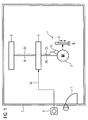
- FIG. 1 shows a servo press 1 with a personal protection device according to the prior art.
- the servo press 1 shown is shown only schematically. It has an electric motor 3 for driving a press ram 2.
- the movement of the press ram 2 is indicated by an arrow up and down.
- the reference numeral 6 denotes a danger area of the servo press 1. In particular, this area is the area below the press ram of the press ram 2.
- the reference numeral 10 shows a rotary encoder, which is exemplary in connection with the electric motor 3 for detecting the rotational movement.
- the rotary encoder 10 may be connected to a mechanical gear arranged between the electric motor 3 and the press ram 2 or an eccentric disk arranged there. With DL a corresponding encoder signal line is designated.
- the reference symbol ML designates the motor lines.
- the entire servo press 1 is separated from a protective fence 5 for the protection of persons against the enclosed danger area 6.
- a closable protective door 7 is provided as an access option, symbolized by a lock.
- the access option may alternatively be a gate, a turnstile, a barrier or the like.
- the servo press 1 can be switched off, for example, via an externally accessible emergency stop switch 8 and the protective door 7 can be unlocked. Upon actuation of the emergency stop switch 8, an electric drive 4 is switched off for the electrical supply of the electric motor 3.
- NL is an associated emergency stop connection line, which connects the emergency stop switch 8 to the electric drive 4, respectively.
- a drive control unit 9 in particular a so-called "motion control" is still available.
- B denotes an exemplary communication bus, by way of which the drive control unit 9 can, inter alia, transmit a drive setpoint to the electric drive 4.
- the drive control unit 9 detects, for the purpose of controlling and regulating the electric drive 4, the rotary encoder signals transmitted via the rotary encoder signal line DL.
- FIG. 2 shows by way of example a sequence for the access of an operator to a servo-press 1 according to the inventive method.
- S0 denotes a start step of the sequence.
- step S1 a request to enter the danger area 6 of the servo-press 1 is requested. If there is a request, then in the subsequent step S2 for approaching an end position of the press ram 2 of the servo press 1, a drive setpoint value is set to the value "0". In other words, the servo press 1 runs out until this end position is reached.
- the drive setpoint may be negative to selectively decelerate the press ram 2 until it reaches this end position.
- step S3 a query is made as to whether this end position has been reached.
- step S5 the holding brake is tested when the drive test setpoint is applied.
- the drive test setpoint is designed so that a driving torque caused thereby can not overcome an effective braking torque of the holding brake.
- step S6 it is checked in step S6 whether the current plunger position has changed. If this is not the case, then there is a secure moment release and an access release of an operator to the servo press.
- Step S10 designates the end of the sequence. If, on the other hand, the plunger position has changed, then a branch is made to a step S8 and, in turn, a secure torque release is effected. If necessary, an error output is made in step S9 in order to indicate to an operator or the monitoring personnel that the servo-press may no longer be made accessible for set-up work.
- FIG. 3 shows an exemplary sequence for monitoring the kinetic energy of a press ram upon release of the danger zone according to the inventive method.
- T0 denotes a start step of the sequence.
- a reduced ram speed is specified. This can, for example, provided for Einricht plante, reduced EinrichtstShtechnikel Ober with speed values in a range of 30 mm / s to 50 mm / s.
- the plunger speed vS is detected securely.
- a value detected for this purpose is compared in step T3 with a maximum permissible speed value vMax. This value vMax is dimensioned such that the holding brake can still decelerate the press ram before the press ram can reach its bottom dead center.
- step T4 a branch is made back to the step T2. Otherwise, in step T4, a safe torque release occurs. In other words, the electric drive for the servo press is released before due to a technical error, the plunger speed vS can increase so that no safe deceleration of the press ram by means of the holding brake is more possible. At the same time, the holding brake is safely controlled in the subsequent step T5 and thereby brought the press ram to a safe stop. Subsequently, an error output is made in step T6 to indicate to the monitoring personnel or the operator the erroneous and no longer permissible behavior of the servo press. With T7, the end of the sequence is according to FIG. 3 designated.
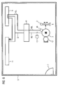
- FIG. 4 shows a schematic representation of the sub-aspect "area protection" of the invention.
- a protective door 7 is again present as an access option for securing the danger zone 6.
- the protective door 7 is part of a surrounding the servo press 1 structural protection device 5.
- the protective device 5 may be, for example, a fence or a wall.
- the protective door 7 has a tumbler 14 for locking this. This guard locking 14 can be released via a controller 11, in particular via a fail-safe controller.
- the reference character FL denotes an enable line
- FR denotes a release feedback line.
- the controller 11 shown is designed to safely perform the functionality of the release device shown.
- the controller 11 preferably redundant, ie dual-channel, executed signal inputs and / or signal outputs.
- AL denotes a request line AL, via which the controller 11 is signaled a request for access.
- Via a release line FR the controller 11 is informed that the protective door 7 is safely released.
- the release device shown preferably fulfills category 3 of the safety standard according to the standard DIN EN 954.
- FIG. 5 shows a schematic representation of the sub-aspect "holding brake".
- the holding brake 12 shown acts, for example, directly for braking or for holding the electric motor 3. It may alternatively be connected to a mechanical gear or to an eccentric disk of the servo press 1.
- the control of the holding brake 12 by means of the controller 11 via two Bremsan Kunststofftechnischen BL. With BR a corresponding brake feedback line is designated.
- the controller 11 outputs a drive test setpoint value TM to the electric drive 4 via the communication bus B. This converts the drive test setpoint TM into a corresponding, for example three-phase, motor current for feeding the downstream electric motor 3.
- a current transformer is provided which is not further described. With WL a corresponding transformer line is referred to, which is fed back to the controller 11. In the event that no current can be detected despite the drive test setpoint TM being output, the controller 11 issues a corresponding error message. At the same time there is a safe torque release of the electric drive. 4
- the controller 11 further checks whether the current position of the press ram 2 has changed. This is done via a two-channel Evaluation of the encoder signals of the rotary encoder 10.
- the reference numeral 13 denotes a motor contactor, via which the motor lines ML for feeding the electric motor 3 can be separated.
- FIG. 6 shows a schematic representation of the sub-aspect "monitoring of kinetic energy".
- the encoder signals via the two encoder signal lines DL two channels are detected by the controller 11.
- the controller 11 can have a safety-related software module which continuously calculates a corresponding ram speed of the press ram 2 by calculation. Due to the two-channel design, a safe detection of the encoder signals according to category 3 of the aforementioned safety standard is possible.
- the rotary encoder 10 is here a two-channel analog rotary encoder.
- FIG. 7 shows a schematic representation of the partial aspect "torque release".
- a two-channel torque release of the electric drive 4 via the two torque-free lines MF is provided.
- MR indicates a corresponding feedback line.
- the electric drive 4 is preferably a drive or converter which already fulfills the safety requirement for category 3, such as, for example, a converter of the SINAMICS type from Siemens.
- the motor contactor 13 is additionally provided as a third shutdown path. This can likewise be controlled by the controller 11 via two contactor control lines SL, ie once again in two channels.
- a corresponding Schützschmelde für SR signals the controller 11 that the contacts of the motor contactor to interrupt the motor current have been opened. Typically, this is done via a positive-guided auxiliary contact of the motor contactor 13.
- the torque release shown in accordance with the category 4 allows a torque release at an extremely high level of security. As a result, setup work for operators on such a servo press 1 are possible without further requirements.
- FIG. 8 Finally, in a schematic representation of the overall concept for a personal protection device for working on a servo press 1. A large part of the safety and monitoring functions is taken over by the designed for a fail-safe operation controller 11.
Landscapes
- Engineering & Computer Science (AREA)
- General Engineering & Computer Science (AREA)
- Mechanical Engineering (AREA)
- Control Of Presses (AREA)
- Bending Of Plates, Rods, And Pipes (AREA)
- Measuring Volume Flow (AREA)
- Grinding-Machine Dressing And Accessory Apparatuses (AREA)
- Physical Vapour Deposition (AREA)
Claims (10)
- Procédé de protection des personnes lorsqu'elles travaillent sur une servopresse ( 1 ) entraînée électriquement, une zone ( 6 ) de danger de la servopresse ( 1 ) étant rendue sûre au moyen d'un dispositif ( 5 ) architectural de protection qui l'entoure et qui a une possibilité d'accès verrouillable et dans lequel il est prévu un frein ( 8 ) d'arrêt de la servopresse ( 1 ), qui est conçu pour freiner un coulisseau ( 2 ) de presse plus une énergie cinétique du coulisseau ( 2 ) de presse lors d'un fonctionnement manuel de réglage, dans lequel on demande à entrer dans la zone ( 6 ) de danger, on teste le fonctionnement du frein ( 8 ) d'arrêt et on libère la possibilité ( 7 ) d'accès si le test du frein d'arrêt est positif, caractérisé en ce qu'après la libération de la possibilité ( 7 ) d'accès, on contrôle la vitesse ( VS ) du coulisseau ( 2 ) de presse jusqu'à une vitesse ( vMax ) maximum admissible pour le fonctionnement de réglage, si la vitesse ( VS ) du coulisseau est dépassée, on déconnecte l'entraînement ( 4 ) et on commande le frein ( 8 ) d'arrêt pour freiner le coulisseau ( 2 ) de la presse.
- Servopresse ayant un dispositif de protection des personnes, la servopresse comportant un coulisseau ( 2 ) de presse, un moteur ( 3 ) électrique pour entraîner le coulisseau ( 2 ) de la presse, un entraînement ( 4 ) électrique pour alimenter le moteur ( 3 ) électrique sur la base d'une valeur de consigne d'entraînement prescrite, un dispositif ( 5 ) architectural de protection entourant la servopresse et ayant une possibilité d'accès verrouillable des personnes pour rendre sûre une zone ( 6 ) de danger de la servopresse, ainsi qu'un dispositif de test de freinage pour tester le frein ( 8 ) d'arrêt sur demande d'entrée dans la zone ( 6 ) de danger, un frein ( 8 ) d'arrêt conçu pour freiner la masse du coulisseau ( 2 ) de la presse plus une énergie cinétique du coulisseau ( 2 ) de la presse, caractérisée par- un dispositif de libération pour libérer la possibilité ( 7 ) d'accès si le test du frein d'arrêt est positif,- une déconnexion instantanée pour déconnecter l'entraînement ( 4 ) électrique et,- un dispositif de contrôle d'une vitesse ( VS ) du coulisseau pour savoir si une vitesse ( vMax ) admissible est dépassée et pour commander la déconnexion instantanée et le frein ( 8 ) d'arrêt, si, alors que la possibilité ( 7 ) d'accès est libérée, la vitesse ( vMax ) admissible est dépassée.
- Servopresse suivant la revendication 2, caractérisée en ce que la vitesse ( vMax ) maximum autorisée est rapportée à une vitesse réduite de réglage pour des travaux de réglage sur la servopresse alors que la possibilité ( 7 ) d'accès est libérée.
- Servopresse suivant la revendication 2 ou 3, caractérisée en ce que la déconnexion instantanée est réalisée par un premier et un deuxième trajets de mise hors circuit de l'entraînement ( 4 ).
- Servopresse suivant l'une des revendications 4, caractérisée en ce que la déconnexion instantanée pour la déconnexion de l'entraînement ( 4 ) électrique est réalisée supplémentairement par un contacteur ( 13 ) de moteur, comme troisième trajet de mise hors circuit, pour séparer l'entraînement ( 4 ) électrique d'une alimentation en énergie.
- Servopresse suivant l'une des revendications 2 à 5, caractérisée en ce que le dispositif de test de frein comporte des moyens pour aller à une position d'extrémité du coulisseau ( 2 ) de la presse sur demande d'entrée dans la zone ( 6 ) de danger, des moyens de commande du frein ( 8 ) d'arrêt, des moyens d'établissement d'une valeur ( TM ) de consigne de test d'entraînement, des moyens de détection de la position du coulisseau ( 2 ) de la presse et des moyens de commande de la déconnexion instantanée si une modification de la position du coulisseau est détectée alors que l'entraînement ( 4 ) est établie.
- Servopresse suivant la revendication 6, caractérisée en ce que le dispositif de test de frein comporte des moyens de détection d'un courant de moteur et en ce que la déconnexion instantanée peut être commandée, si l'on ne peut pas détecter de courant de moteur alors que l'entraînement ( 4 ) est établi.
- Servopresse suivant l'une des revendications 2 à 7, caractérisée en ce que la déconnexion instantanée comporte, pour la déconnexion de l'entraînement ( 4 ) électrique, un étage de sécurité au moins de la catégorie ( 4 ) suivant la norme DIN EN 954.
- Servopresse suivant l'une des revendications 2 à 8, caractérisée en ce que la détection d'une position du coulisseau de la presse et/ou la détection de l'état du dispositif de libération s'effectue au moins par deux canaux.
- Servopresse suivant l'une des revendications 2 à 9, caractérisée en ce qu'au moins des parties de la fonction du dispositif de test de frein, du dispositif de libération, de la déconnexion instantanée et du dispositif de contrôle sont rassemblés dans une commande ( 11 ) électronique, notamment dans une commande électronique anti-panne ayant des entrées et des sorties réalisées en deux canaux.
Applications Claiming Priority (2)
| Application Number | Priority Date | Filing Date | Title |
|---|---|---|---|
| DE102007033712 | 2007-07-19 | ||
| PCT/EP2008/059242 WO2009010511A1 (fr) | 2007-07-19 | 2008-07-15 | Procédé destiné à protéger des personnes dans le cadre de leur travail sur une servopresse, et servopresse comprenant un dispositif de protection des personnes |
Publications (3)
| Publication Number | Publication Date |
|---|---|
| EP2047171A1 EP2047171A1 (fr) | 2009-04-15 |
| EP2047171B1 true EP2047171B1 (fr) | 2011-03-02 |
| EP2047171B2 EP2047171B2 (fr) | 2020-07-29 |
Family
ID=40029181
Family Applications (1)
| Application Number | Title | Priority Date | Filing Date |
|---|---|---|---|
| EP08786151.4A Active EP2047171B2 (fr) | 2007-07-19 | 2008-07-15 | Procede destine a proteger des personnes dans le cadre de leur travail sur une servopresse, et servopresse comprenant un dispositif de protection des personnes |
Country Status (4)
| Country | Link |
|---|---|
| EP (1) | EP2047171B2 (fr) |
| AT (1) | ATE500463T1 (fr) |
| DE (1) | DE502008002713D1 (fr) |
| WO (1) | WO2009010511A1 (fr) |
Families Citing this family (1)
| Publication number | Priority date | Publication date | Assignee | Title |
|---|---|---|---|---|
| JP5577365B2 (ja) * | 2012-03-15 | 2014-08-20 | コマツ産機株式会社 | プレス機械の制動性能確認装置 |
Family Cites Families (5)
| Publication number | Priority date | Publication date | Assignee | Title |
|---|---|---|---|---|
| GB638129A (en) * | 1948-05-18 | 1950-05-31 | Press Guards Ltd | A new or improved guard for milling machines |
| US6283514B1 (en) * | 1996-08-16 | 2001-09-04 | K. A. Schmersal Gmbh & Co. | Apparatus for monitoring and controlling access to a restricted area |
| US6389875B1 (en) * | 1998-10-02 | 2002-05-21 | Ralph L. Barnett | Zero speed indicating devices and process of testing same |
| DE102005012876A1 (de) * | 2005-03-19 | 2006-09-21 | Müller Weingarten AG | Verfahren und Vorrichtung zur Steuerung und Regelung von servo-elektrischen Ziehkissen |
| DE102005040263A1 (de) * | 2005-08-24 | 2007-03-01 | Müller Weingarten AG | Verfahren und Vorrichtung zur Steuerung und Regelung der Stößelbewegung an servo-elektrischen Pressen |
-
2008
- 2008-07-15 DE DE502008002713T patent/DE502008002713D1/de active Active
- 2008-07-15 WO PCT/EP2008/059242 patent/WO2009010511A1/fr not_active Ceased
- 2008-07-15 EP EP08786151.4A patent/EP2047171B2/fr active Active
- 2008-07-15 AT AT08786151T patent/ATE500463T1/de active
Also Published As
| Publication number | Publication date |
|---|---|
| EP2047171A1 (fr) | 2009-04-15 |
| EP2047171B2 (fr) | 2020-07-29 |
| WO2009010511A1 (fr) | 2009-01-22 |
| DE502008002713D1 (de) | 2011-04-14 |
| ATE500463T1 (de) | 2011-03-15 |
Similar Documents
| Publication | Publication Date | Title |
|---|---|---|
| EP0243728B2 (fr) | Système de sécurité pour une machine à imprimer | |
| DE112009004592B4 (de) | Aufzuganlage und Verfahren zum Überprüfen derselben | |
| EP2859226B1 (fr) | Système de sécurité pour éolienne | |
| DE3723205A1 (de) | Hilfskraftlenkung, insbesondere fuer kraftfahrzeuge | |
| DE102011002481A1 (de) | Steuerungssystem | |
| EP1882802A2 (fr) | Procédé destiné au ralentissement sécurisé d'un portail tout comme dispositif destiné à la réalisation du procédé | |
| EP2160349B1 (fr) | Agencement, module et procédé pour le fonctionnement sûr d'une installation | |
| EP0501218A2 (fr) | Système de contrôle d'une porte ou d'un dispositif de sécurité de machines | |
| EP1253490A2 (fr) | Procédé et dispositif de surveillance sécurisée de la vitesse | |
| EP2047171B1 (fr) | Procede destine a proteger des personnes dans le cadre de leur travail sur une servopresse, et servopresse comprenant un dispositif de protection des personnes | |
| DE102008051779A1 (de) | Fertigungseinheit sowie Verfahren zum Betreiben der Fertigungseinheit | |
| DE102010051413B4 (de) | Antriebssystem und Verfahren zum Betreiben eines Antriebssystems für eine Achse einer Maschine oder eine Anlage | |
| EP2175552A1 (fr) | Procédé de fonctionnement d'un dispositif d'entraînement et dispositif d'entraînement destiné à l'exécution du procédé | |
| EP1274644A1 (fr) | Procede et dispositif permettant de regler le/les frein(s) d'une installation de transport de personnes | |
| EP1050708B1 (fr) | Dispositif de contrôle de fonctions relatives à la sécurité d'une machine présentant des dangers | |
| DE10052316A1 (de) | Vorrichtung zur Ansteuerung einer elektrischen Sicherungseinrichtung für ein Kraftfahrzeug | |
| EP2981716B1 (fr) | Procédé et dispositif permettant de coupler et/ou de découpler un entraînement auxiliaire de transmission, éolienne | |
| EP0824969A2 (fr) | Système de commande pour centrifugeuse pour laboratoire | |
| DE102014226617A1 (de) | Antriebsregelvorrichtung für einen elektro-hydraulischen Antrieb | |
| DE102019112712A1 (de) | Schalteranordnung mit antriebssystem und verfahren zum sicheren betrieb einer schalteranordnung | |
| DE19643408C2 (de) | Notbetriebssteuerung für ein Hebezeug | |
| EP4095645A1 (fr) | Circuit d'actionneur d'entrainement pour configuration et test sûrs | |
| DE9102270U1 (de) | Tür- oder Schutzhaubenverriegelungssteuerung für eine Schutzeinrichtung bei Maschinen | |
| DE102012012047A1 (de) | Antriebsregler und Verfahren zur Stillsetzung einer Achse | |
| DE102017204123A1 (de) | Verfahren zum Bremsen einer Maschine und Maschine |
Legal Events
| Date | Code | Title | Description |
|---|---|---|---|
| PUAI | Public reference made under article 153(3) epc to a published international application that has entered the european phase |
Free format text: ORIGINAL CODE: 0009012 |
|
| 17P | Request for examination filed |
Effective date: 20090304 |
|
| AK | Designated contracting states |
Kind code of ref document: A1 Designated state(s): AT BE BG CH CY CZ DE DK EE ES FI FR GB GR HR HU IE IS IT LI LT LU LV MC MT NL NO PL PT RO SE SI SK TR |
|
| AX | Request for extension of the european patent |
Extension state: AL BA MK RS |
|
| 17Q | First examination report despatched |
Effective date: 20090608 |
|
| GRAP | Despatch of communication of intention to grant a patent |
Free format text: ORIGINAL CODE: EPIDOSNIGR1 |
|
| GRAC | Information related to communication of intention to grant a patent modified |
Free format text: ORIGINAL CODE: EPIDOSCIGR1 |
|
| GRAS | Grant fee paid |
Free format text: ORIGINAL CODE: EPIDOSNIGR3 |
|
| GRAA | (expected) grant |
Free format text: ORIGINAL CODE: 0009210 |
|
| AK | Designated contracting states |
Kind code of ref document: B1 Designated state(s): AT BE BG CH CY CZ DE DK EE ES FI FR GB GR HR HU IE IS IT LI LT LU LV MC MT NL NO PL PT RO SE SI SK TR |
|
| REG | Reference to a national code |
Ref country code: GB Ref legal event code: FG4D Free format text: NOT ENGLISH |
|
| REG | Reference to a national code |
Ref country code: CH Ref legal event code: EP |
|
| REG | Reference to a national code |
Ref country code: IE Ref legal event code: FG4D Free format text: LANGUAGE OF EP DOCUMENT: GERMAN |
|
| REF | Corresponds to: |
Ref document number: 502008002713 Country of ref document: DE Date of ref document: 20110414 Kind code of ref document: P |
|
| REG | Reference to a national code |
Ref country code: DE Ref legal event code: R096 Ref document number: 502008002713 Country of ref document: DE Effective date: 20110414 |
|
| REG | Reference to a national code |
Ref country code: NL Ref legal event code: VDEP Effective date: 20110302 |
|
| PG25 | Lapsed in a contracting state [announced via postgrant information from national office to epo] |
Ref country code: LV Free format text: LAPSE BECAUSE OF FAILURE TO SUBMIT A TRANSLATION OF THE DESCRIPTION OR TO PAY THE FEE WITHIN THE PRESCRIBED TIME-LIMIT Effective date: 20110302 Ref country code: SE Free format text: LAPSE BECAUSE OF FAILURE TO SUBMIT A TRANSLATION OF THE DESCRIPTION OR TO PAY THE FEE WITHIN THE PRESCRIBED TIME-LIMIT Effective date: 20110302 Ref country code: NO Free format text: LAPSE BECAUSE OF FAILURE TO SUBMIT A TRANSLATION OF THE DESCRIPTION OR TO PAY THE FEE WITHIN THE PRESCRIBED TIME-LIMIT Effective date: 20110602 Ref country code: HR Free format text: LAPSE BECAUSE OF FAILURE TO SUBMIT A TRANSLATION OF THE DESCRIPTION OR TO PAY THE FEE WITHIN THE PRESCRIBED TIME-LIMIT Effective date: 20110302 Ref country code: LT Free format text: LAPSE BECAUSE OF FAILURE TO SUBMIT A TRANSLATION OF THE DESCRIPTION OR TO PAY THE FEE WITHIN THE PRESCRIBED TIME-LIMIT Effective date: 20110302 Ref country code: GR Free format text: LAPSE BECAUSE OF FAILURE TO SUBMIT A TRANSLATION OF THE DESCRIPTION OR TO PAY THE FEE WITHIN THE PRESCRIBED TIME-LIMIT Effective date: 20110603 Ref country code: ES Free format text: LAPSE BECAUSE OF FAILURE TO SUBMIT A TRANSLATION OF THE DESCRIPTION OR TO PAY THE FEE WITHIN THE PRESCRIBED TIME-LIMIT Effective date: 20110613 |
|
| LTIE | Lt: invalidation of european patent or patent extension |
Effective date: 20110302 |
|
| PG25 | Lapsed in a contracting state [announced via postgrant information from national office to epo] |
Ref country code: NL Free format text: LAPSE BECAUSE OF FAILURE TO SUBMIT A TRANSLATION OF THE DESCRIPTION OR TO PAY THE FEE WITHIN THE PRESCRIBED TIME-LIMIT Effective date: 20110302 Ref country code: SI Free format text: LAPSE BECAUSE OF FAILURE TO SUBMIT A TRANSLATION OF THE DESCRIPTION OR TO PAY THE FEE WITHIN THE PRESCRIBED TIME-LIMIT Effective date: 20110302 Ref country code: CY Free format text: LAPSE BECAUSE OF FAILURE TO SUBMIT A TRANSLATION OF THE DESCRIPTION OR TO PAY THE FEE WITHIN THE PRESCRIBED TIME-LIMIT Effective date: 20110302 Ref country code: FI Free format text: LAPSE BECAUSE OF FAILURE TO SUBMIT A TRANSLATION OF THE DESCRIPTION OR TO PAY THE FEE WITHIN THE PRESCRIBED TIME-LIMIT Effective date: 20110302 Ref country code: BG Free format text: LAPSE BECAUSE OF FAILURE TO SUBMIT A TRANSLATION OF THE DESCRIPTION OR TO PAY THE FEE WITHIN THE PRESCRIBED TIME-LIMIT Effective date: 20110602 |
|
| REG | Reference to a national code |
Ref country code: IE Ref legal event code: FD4D |
|
| PG25 | Lapsed in a contracting state [announced via postgrant information from national office to epo] |
Ref country code: EE Free format text: LAPSE BECAUSE OF FAILURE TO SUBMIT A TRANSLATION OF THE DESCRIPTION OR TO PAY THE FEE WITHIN THE PRESCRIBED TIME-LIMIT Effective date: 20110302 Ref country code: PT Free format text: LAPSE BECAUSE OF FAILURE TO SUBMIT A TRANSLATION OF THE DESCRIPTION OR TO PAY THE FEE WITHIN THE PRESCRIBED TIME-LIMIT Effective date: 20110704 Ref country code: IE Free format text: LAPSE BECAUSE OF FAILURE TO SUBMIT A TRANSLATION OF THE DESCRIPTION OR TO PAY THE FEE WITHIN THE PRESCRIBED TIME-LIMIT Effective date: 20110302 |
|
| PG25 | Lapsed in a contracting state [announced via postgrant information from national office to epo] |
Ref country code: IS Free format text: LAPSE BECAUSE OF FAILURE TO SUBMIT A TRANSLATION OF THE DESCRIPTION OR TO PAY THE FEE WITHIN THE PRESCRIBED TIME-LIMIT Effective date: 20110702 Ref country code: RO Free format text: LAPSE BECAUSE OF FAILURE TO SUBMIT A TRANSLATION OF THE DESCRIPTION OR TO PAY THE FEE WITHIN THE PRESCRIBED TIME-LIMIT Effective date: 20110302 Ref country code: CZ Free format text: LAPSE BECAUSE OF FAILURE TO SUBMIT A TRANSLATION OF THE DESCRIPTION OR TO PAY THE FEE WITHIN THE PRESCRIBED TIME-LIMIT Effective date: 20110302 Ref country code: SK Free format text: LAPSE BECAUSE OF FAILURE TO SUBMIT A TRANSLATION OF THE DESCRIPTION OR TO PAY THE FEE WITHIN THE PRESCRIBED TIME-LIMIT Effective date: 20110302 |
|
| PLBI | Opposition filed |
Free format text: ORIGINAL CODE: 0009260 |
|
| PG25 | Lapsed in a contracting state [announced via postgrant information from national office to epo] |
Ref country code: MT Free format text: LAPSE BECAUSE OF FAILURE TO SUBMIT A TRANSLATION OF THE DESCRIPTION OR TO PAY THE FEE WITHIN THE PRESCRIBED TIME-LIMIT Effective date: 20110302 |
|
| PLAX | Notice of opposition and request to file observation + time limit sent |
Free format text: ORIGINAL CODE: EPIDOSNOBS2 |
|
| 26 | Opposition filed |
Opponent name: SCHULER PRESSEN GMBH Effective date: 20111201 Opponent name: BOSCH REXROTH AG Effective date: 20111202 |
|
| BERE | Be: lapsed |
Owner name: SIEMENS A.G. Effective date: 20110731 |
|
| PG25 | Lapsed in a contracting state [announced via postgrant information from national office to epo] |
Ref country code: MC Free format text: LAPSE BECAUSE OF NON-PAYMENT OF DUE FEES Effective date: 20110731 Ref country code: PL Free format text: LAPSE BECAUSE OF FAILURE TO SUBMIT A TRANSLATION OF THE DESCRIPTION OR TO PAY THE FEE WITHIN THE PRESCRIBED TIME-LIMIT Effective date: 20110302 |
|
| REG | Reference to a national code |
Ref country code: DE Ref legal event code: R026 Ref document number: 502008002713 Country of ref document: DE Effective date: 20111202 |
|
| REG | Reference to a national code |
Ref country code: FR Ref legal event code: ST Effective date: 20120330 |
|
| PG25 | Lapsed in a contracting state [announced via postgrant information from national office to epo] |
Ref country code: BE Free format text: LAPSE BECAUSE OF NON-PAYMENT OF DUE FEES Effective date: 20110731 Ref country code: FR Free format text: LAPSE BECAUSE OF NON-PAYMENT OF DUE FEES Effective date: 20110801 |
|
| PLBB | Reply of patent proprietor to notice(s) of opposition received |
Free format text: ORIGINAL CODE: EPIDOSNOBS3 |
|
| PG25 | Lapsed in a contracting state [announced via postgrant information from national office to epo] |
Ref country code: IT Free format text: LAPSE BECAUSE OF FAILURE TO SUBMIT A TRANSLATION OF THE DESCRIPTION OR TO PAY THE FEE WITHIN THE PRESCRIBED TIME-LIMIT Effective date: 20110302 |
|
| REG | Reference to a national code |
Ref country code: CH Ref legal event code: PL |
|
| RAP2 | Party data changed (patent owner data changed or rights of a patent transferred) |
Owner name: SIEMENS AKTIENGESELLSCHAFT |
|
| GBPC | Gb: european patent ceased through non-payment of renewal fee |
Effective date: 20120715 |
|
| PG25 | Lapsed in a contracting state [announced via postgrant information from national office to epo] |
Ref country code: LI Free format text: LAPSE BECAUSE OF NON-PAYMENT OF DUE FEES Effective date: 20120731 Ref country code: GB Free format text: LAPSE BECAUSE OF NON-PAYMENT OF DUE FEES Effective date: 20120715 Ref country code: CH Free format text: LAPSE BECAUSE OF NON-PAYMENT OF DUE FEES Effective date: 20120731 |
|
| PG25 | Lapsed in a contracting state [announced via postgrant information from national office to epo] |
Ref country code: LU Free format text: LAPSE BECAUSE OF NON-PAYMENT OF DUE FEES Effective date: 20110715 |
|
| PG25 | Lapsed in a contracting state [announced via postgrant information from national office to epo] |
Ref country code: TR Free format text: LAPSE BECAUSE OF FAILURE TO SUBMIT A TRANSLATION OF THE DESCRIPTION OR TO PAY THE FEE WITHIN THE PRESCRIBED TIME-LIMIT Effective date: 20110302 |
|
| PG25 | Lapsed in a contracting state [announced via postgrant information from national office to epo] |
Ref country code: HU Free format text: LAPSE BECAUSE OF FAILURE TO SUBMIT A TRANSLATION OF THE DESCRIPTION OR TO PAY THE FEE WITHIN THE PRESCRIBED TIME-LIMIT Effective date: 20110302 |
|
| REG | Reference to a national code |
Ref country code: AT Ref legal event code: MM01 Ref document number: 500463 Country of ref document: AT Kind code of ref document: T Effective date: 20130715 |
|
| PLCK | Communication despatched that opposition was rejected |
Free format text: ORIGINAL CODE: EPIDOSNREJ1 |
|
| PG25 | Lapsed in a contracting state [announced via postgrant information from national office to epo] |
Ref country code: AT Free format text: LAPSE BECAUSE OF NON-PAYMENT OF DUE FEES Effective date: 20130715 |
|
| APBM | Appeal reference recorded |
Free format text: ORIGINAL CODE: EPIDOSNREFNO |
|
| APBP | Date of receipt of notice of appeal recorded |
Free format text: ORIGINAL CODE: EPIDOSNNOA2O |
|
| APAH | Appeal reference modified |
Free format text: ORIGINAL CODE: EPIDOSCREFNO |
|
| APBQ | Date of receipt of statement of grounds of appeal recorded |
Free format text: ORIGINAL CODE: EPIDOSNNOA3O |
|
| RAP2 | Party data changed (patent owner data changed or rights of a patent transferred) |
Owner name: SIEMENS AKTIENGESELLSCHAFT |
|
| PLAB | Opposition data, opponent's data or that of the opponent's representative modified |
Free format text: ORIGINAL CODE: 0009299OPPO |
|
| R26 | Opposition filed (corrected) |
Opponent name: SCHULER PRESSEN GMBH Effective date: 20111201 |
|
| PLAB | Opposition data, opponent's data or that of the opponent's representative modified |
Free format text: ORIGINAL CODE: 0009299OPPO |
|
| R26 | Opposition filed (corrected) |
Opponent name: SCHULER PRESSEN GMBH Effective date: 20111201 |
|
| APBU | Appeal procedure closed |
Free format text: ORIGINAL CODE: EPIDOSNNOA9O |
|
| PUAH | Patent maintained in amended form |
Free format text: ORIGINAL CODE: 0009272 |
|
| STAA | Information on the status of an ep patent application or granted ep patent |
Free format text: STATUS: PATENT MAINTAINED AS AMENDED |
|
| 27A | Patent maintained in amended form |
Effective date: 20200729 |
|
| AK | Designated contracting states |
Kind code of ref document: B2 Designated state(s): AT BE BG CH CY CZ DE DK EE ES FI FR GB GR HR HU IE IS IT LI LT LU LV MC MT NL NO PL PT RO SE SI SK TR |
|
| REG | Reference to a national code |
Ref country code: DE Ref legal event code: R102 Ref document number: 502008002713 Country of ref document: DE |
|
| PGFP | Annual fee paid to national office [announced via postgrant information from national office to epo] |
Ref country code: DE Payment date: 20250919 Year of fee payment: 18 |