EP2047370B1 - Verfahren und vorrichtung zum verteilen von usb-hub-funktionen über ein netzwerk - Google Patents
Verfahren und vorrichtung zum verteilen von usb-hub-funktionen über ein netzwerk Download PDFInfo
- Publication number
- EP2047370B1 EP2047370B1 EP07785007.1A EP07785007A EP2047370B1 EP 2047370 B1 EP2047370 B1 EP 2047370B1 EP 07785007 A EP07785007 A EP 07785007A EP 2047370 B1 EP2047370 B1 EP 2047370B1
- Authority
- EP
- European Patent Office
- Prior art keywords
- usb
- extender
- local
- host computer
- remote
- Prior art date
- Legal status (The legal status is an assumption and is not a legal conclusion. Google has not performed a legal analysis and makes no representation as to the accuracy of the status listed.)
- Not-in-force
Links
Images




Classifications
-
- G—PHYSICS
- G06—COMPUTING OR CALCULATING; COUNTING
- G06F—ELECTRIC DIGITAL DATA PROCESSING
- G06F13/00—Interconnection of, or transfer of information or other signals between, memories, input/output devices or central processing units
- G06F13/38—Information transfer, e.g. on bus
- G06F13/40—Bus structure
- G06F13/4004—Coupling between buses
- G06F13/4027—Coupling between buses using bus bridges
- G06F13/4045—Coupling between buses using bus bridges where the bus bridge performs an extender function
Definitions
- This invention relates to methods and apparatus for transmitting signals between computers and devices using Universal Serial Bus (USB) ports, and, in particular, to a method for operating a plurality of USB peripheral devices distributed across a data communications network.
- USB Universal Serial Bus
- USB Universal Serial Bus
- USB was created by an alliance of seven of the largest companies in the computer and communication markets. Those companies were Intel, Compaq, Microsoft, NorTel, NEC, Digital and IBM.
- the specifications defining USB e.g. Intel et al., Universal Serial Bus Specification, Revision 1.0, January 1996; and updated as Revision 1.1 in Sep. 23, 1998, and further updated as Revision 2.0 in April 2000, and subsequent updates, additions and modifications --hereinafter collectively referred to as the "USB Specification", which term can include future modifications and revisions
- USB-IF USB Implementers Forum
- the USB Specification establishes a number of criteria which must be met in order to comply with USB standards.
- the USB Specification also defines a number of terms, which definitions are adopted for the purposes of this specification.
- USB host controller unit installed, preferably, in a host computer. Furthermore, said data communication occurs in a series of USB transactions wherein each USB transaction is initiated by a USB host controller and is composed of one, two or three subactions. Each subaction is terminated by a reversal in the direction of data flow.
- USB Hubs--devices that are intended to support increased populations rather than increased distances--this distance limitation can be increased, in theory, to 30 meters.
- this multiple hub solution is both expensive and clumsy.
- the major factor that limits the extent to which the range of USB can be extended is transmission delay.
- the USB Specification allows a maximum period of approximately 1.5 microseconds for the round-trip delay of a single communication from a host computer to a device and back to the computer.
- the round-trip delay budget of 1.5 microseconds is composed of two approximately equal parts, namely, the transmission delay in both directions between the host computer and the device and secondly, the turn-around time required by the device to create the desired response.
- the approach described in US Patent No. 6381666 removed this restriction on the upper limit of round-trip delay.
- USB hub be employed whenever multiple USB peripheral devices are required to be connected simultaneously to a single port on a USB host controller. It is an attribute of a USB hub that said hub be equipped with a single upstream port for connecting to a USB host controller (or upstream hub) and a plurality of downstream ports for connecting to a plurality of USB peripheral devices (or downstream hubs).
- the USB driver software resident in the host computer that contains the USB host controller is aware of the connection topology of USB hubs and USB peripheral devices and will fail to operate if said topology is not maintained.
- USB hub be connected between said USB peripheral devices and said USB host controller and that said USB hub must be equipped with an individual downstream port for each USB peripheral device.
- it is desired to insert a data communications network between said USB hub and said USB peripheral devices then it would be advantageous to concentrate all USB traffic travelling between said USB hub and said data communications network over a single physical connection.
- each downstream port of a USB hub supports control and monitoring of the physical connection between said downstream port and any USB peripheral device that may be connected thereto.
- said downstream port must be able to detect the connection and disconnection of a USB peripheral device, and must be able to reset, suspend and resume the operation of said USB peripheral device. It would be advantageous to maintain said connection, disconnection, reset, suspend and resume capabilities normally associated with individual physical connections when said individual physical connections are replaced by a shared connection to a data communications network.
- USB/IP - a Peripheral Bus Extension for Device Sharing over IP Network
- Hirofuchi et. al USENIX Association
- FREENIX Track 2005 Annual Technical Conference, pages 47-60
- a system for connecting USB devices to a host computer over a network is described.
- Hirofuchi provides greater distances, there is no mention of providing a system which can handle transmissions having time delays which are longer than that allowed under the USB specification.
- USB technology as described in US 6381666 has proven to be useful in point-to-point configurations, it would still be desirable to provide improvements to the technology by providing an improved method and apparatus for enabling a plurality of peripheral devices, utilizing the USB specification, to be distributed at various locations across a network, wherein said network may exhibit long transmission delays.
- said host computer may be connected to said data communications network through a single physical connection.
- said data communications network may exhibit transmission delays that exceed the parameters defined by the USB Specification.
- said plurality of USB peripheral devices and said USB host controller may operate at any of the data rates permitted under the USB 2.0 Specification.
- a virtual USB peripheral device may be connected to said virtual USB hub.
- USB device management functions of connection, disconnection, reset, suspend and resume shall operate consistent with the prior art USB specifications when the prior art physical connections are replaced by a network connection as described by the present invention.
- the apparatus be very cost effective, consistent with the broadest population of devices targeted by the USB industry.
- the present invention provides a method and related apparatus, wherein a host computer is connected to a local extender device which, in turn, is connected to one or a plurality of remote extender devices through a data communications network.
- the remote extender devices are, in turn, connected to a plurality of conventional USB peripheral devices, wherein signals between said host computer and said USB peripheral devices are processed in the local extender and/or the remote extenders so as to allow the host computer and the USB peripheral devices to operate in the presence of transmission delays greater than that normally allowed in the USB specification.
- the invention is of most utility when the round-trip transmission delay between the host computer and the USB peripheral device exceeds 1 microsecond.
- the present invention is defined according to the method of claim 1 and the system of claim 10.
- the host computer and the USB peripheral device can be any standard unit or device that supports the USB Specification. Preferably, no modifications to either the hardware or the software of said host computer are required.
- the local extender is preferably a self-contained unit that connects to said host computer through a standard USB cable.
- the remote extender is preferably a self-contained unit that connects to said host computer through a standard USB cable.
- the remote extender is preferably a self-contained unit that connects to said plurality of USB peripheral devices through a plurality of standard USB cables.
- the data communications network is not limited to any particular transmission media or protocol, but can, in operation, introduce a round-trip transmission delay between said host computer and said plurality of USB peripheral devices in excess of 1 microsecond. It is a necessary attribute of said data communications network that it provide a communications path between at least one local extender unit and at least one remote extender unit. It is preferable that said data communications network provide a communications path between at least one local extender unit and a plurality of remote extender units (a point-to-multipoint configuration). Networks such as those based on wired Ethernet, wireless Ethernet, IEEE 802.15.3, and the Internet are, for example, compliant with these requirements.
- the method and apparatus of the present invention are most preferably used in a system wherein said host computer is a personal computer, and said plurality of USB peripheral devices are comprised of USB flash drives, USB hard drives, USB CD/DVD drives, USB cameras, USB mice, USB keyboards, USB hubs or any other device which is compatible with the USB Specification.
- said host computer is a personal computer
- said plurality of USB peripheral devices are comprised of USB flash drives, USB hard drives, USB CD/DVD drives, USB cameras, USB mice, USB keyboards, USB hubs or any other device which is compatible with the USB Specification.
- the local extender includes an upstream transceiver and a downstream transceiver, and the upstream transceiver is a standard USB transceiver and the downstream transceiver is a wireless transceiver.
- the upstream transceiver is a standard USB transceiver and the downstream transceiver is an Ethernet transceiver.
- the remote extender includes an upstream transceiver and a downstream transceiver, and the upstream transceiver is a wireless transceiver and the downstream transceiver is a standard USB transceiver.
- the upstream transceiver is an Ethernet transceiver and the downstream transceiver is a standard USB transceiver.
- FIG. 1 is a block diagram of a prior art system assembled according to the USB Specifications.
- a USB-enabled computer (20) may be connected to a plurality of USB devices (40 - 45) through a USB hub (31) and through a chain of USB hubs (31 and 32, and 31 to 34).
- a device cannot be connected to another device and the maximum number of hubs that can be connected in a single serial chain is five.
- the maximum length of each cable used to interconnect a computer, hub or device is 5 metres.
- FIG. 2 is a block diagram of a system for communicating with USB devices across a network, according to the present invention.
- USB subactions including input/output operations for host computer (20) are intercepted by a local extender (50) which is connected to said host computer through a standard USB cable.
- the local extender (50) preferably generates a "modified" form of the USB protocol that is delivered over network "(21) to a plurality of remote extenders (51a, 51b, 51c) which can be located at an extended distance from said local extender (50).
- Hubs 32, and 33, and device 42 are connected to remote extenders 51a, 51b, and 51c, as previously described.
- a host computer (20), and a local extender (50) are assembled as individual units. It will be apparent to those skilled in the art though that different combinations of these components might be used and that alternative packaging arrangements are possible.
- Each remote extender (51a, 51b, 51c) receives signals from the network (21) and then, if necessary, preferably converts the received signals to electrical signals compatible with the USB protocol and delivers these electrical signals over USB cables to directly connected USB hubs (32, 33) and USB peripheral device (42). Signals are relayed to indirectly connected USB peripheral devices (40, 41, 43, 44, 45) and to indirectly connected USB hub (34) by USB hubs (32, 33). The reverse process occurs when signals are passed from USB peripheral devices (40-45) to host computer (20).
- a remote extender (51b) and a USB peripheral device (42) are assembled as individual units. It will be apparent to those skilled in the art though that different combinations of these components might be used and that alternative packaging arrangements are possible.
- a remote extender (51a) and a USB hub (32) are assembled as individual units. It will again be apparent to those skilled in the art that different combinations of these components might be used and that alternative packaging arrangements are possible.
- the data communications network (21) is a wired Ethernet network and the round-trip delay between host computer (20) and USB peripheral device (42) can be up to, for example, 1 millisecond or more. In other embodiments, however, the data communications network can be changed.
- the data communications network (21) can be a wireless network and the round-trip delay between host computer (20) and USB peripheral device (42) can be up to, for example, 100 milliseconds or more.
- the data communications network (21) can be an internet connection and the round-trip delay between host computer (20) and USB peripheral device (42) can be up to, for example, 1 second or more.
- FIG. 3 is a block diagram of a prior art USB hub assembled according to the USB specification.
- Said USB hub is equipped with an upstream port (60) for communicating with a host computer or upstream hub, and a plurality of downstream ports (65a, 65b, 65c) for communicating with a plurality of USB devices or downstream USB hubs.
- a USB subaction arriving at upstream port (60) is forwarded to hub repeater (62) which determines whether said USB subaction can be forwarded directly to one of the downstream ports (65a, 65b, 65c) or must be directed towards transaction translator (61) or hub controller (63).
- a USB subaction that must be converted from high-speed format to classic-speed format is directed towards transaction translator (61).
- a USB subaction that relates to the internal operation of the hub is directed towards hub controller (63).
- a USB subaction that relates to the status of the USB peripheral devices that are directly connected to downstream ports (65a, 65b, 65c) is directed towards hub controller (63).
- a USB subaction that arrives at transaction translator (61) from hub repeater (62) is converted from high-speed to classic-speed format by said transaction translator (61) and then forwarded to the appropriate downstream port (65a, 65b or 65c) through routing logic (64).
- a high-speed USB subaction arriving at any downstream port is forwarded by routing logic (64) to hub repeater (62) which in turn forwards said high-speed USB subaction to upstream port (60).
- a classic-speed USB subaction arriving at downstream port (65a, 65b or 65c) is forwarded by routing logic (64) to transaction translator (61) where said classic-speed USB subaction is converted to high-speed USB format before being forwarded to hub repeater (62) and thereafter to upstream port (60).
- the number of upstream ports is typically one, but the number of downstream ports can vary from 1 to 255, and is not limited to the three ports shown.
- FIG 4 is a block diagram showing the distribution of USB hub functions across a network according to the present invention.
- the following description will describe the operation of the invention with respect to remote extender (51b) for illustration of the method but it will be clear to those skilled in the art that a similar description applies to remote extenders (51a) and (51c) and that additional remote extenders may be deployed beyond the three units shown in Figure 4 , up to the maximum number of ports allowed for a USB hub (e.g. currently to a maximum of 255 ports).
- the upstream port (60) and hub controller (63) are located within the local extender (50).
- the hub repeater function (62) from Figure 3 for providing connectivity between the remaining hub functions, is duplicated as a local repeater (71) within local extender (50), and as a remote repeater (75b) in remote extender (51b).
- the transaction translator (61) from Figure 3 is located within remote extender (51b) as transaction translator (61b).
- the downstream port (65b) from Figure 3 is located within remote extender (51b) as downstream port (65b).
- routing logic (64) from Figure 3 is replaced by a local router (72) in local extender (50) and a remote router (74b) in remote extender (51b). Whereas in a conventional USB hub, routing logic (64) is required to direct traffic to a specific port (65a, 65b or 65c), in the present invention the replacement logic (72 and 74b) is required to direct traffic to a specific network node that identifies remote extenders (51a, 51b or 51c) or local extender (50).
- hub controller (63) is enhanced by the addition of virtual ports (73a, 73b, 73c), wherein said virtual ports provide to said hub controller (63) a local mechanism for maintaining the status of physical downstream ports (65a, 65b, 65c).
- each local virtual port e.g. 73b
- each local virtual port provides local emulation of its corresponding remote physical port (e.g. 65b), enabling hub controller (63) to operate on a local resource (73b) while said virtual port (73b) is responsible for relaying operations to remote physical port (65b).
- a similar process occurs in the opposite direction when a physical event occurring at remote physical port (65b) is relayed to corresponding local virtual port (73b) and said local virtual port (73b) is then responsible for informing hub controller (63) of said physical event.
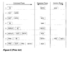
- FIG. 5 is a timing diagram of typical USB transactions according to the prior art USB Specifications.
- a USB transaction consists of one, two or three phases, in which a phase is terminated by a reversal in the direction of data flow.
- Each phase can contain zero, one or more discrete USB packets.
- the set of packets that comprise a single phase is described herein as a USB subaction.
- transaction #1 occupies three phases and is an example of an IN command addressed to an asynchronous endpoint.
- Transaction #2 occupies one phase and is an example of an OUT command addressed to an isochronous endpoint.
- Transactions #3, #6 and #8 occupy two phases and are examples of OUT commands addressed to asynchronous endpoints.
- Additional transactions #4 and #5 also occupy two phases and are further examples of IN commands addressed to asynchronous endpoints.
- Transaction #7 occupies three phases and is an example of an IN command addressed to a low-speed asynchronous endpoint.
- FIG. 6 is an enhanced block diagram of a local extender unit (50) according to the invention.
- a particular enhancement included in said local extender unit (50) is the addition of virtual device controller (83).
- Said virtual device controller (83) can be configured to emulate the operation of a physical USB device or devices and can thereby be used to add value-added features to said local extender unit (50).
- said virtual device controller (83) emulates a radio management function and can be used to control the physical parameters of network transceiver (84).
- said virtual device controller (83) emulates a network interface card and can be used to transmit TCP/IP packets across data communications network (21). It will be apparent to those skilled in the art that these functions are not unique and that other functions may be performed in a similar manner.
- a USB subaction originating from host computer (20) is received by USB transceiver (81) and forwarded through upstream port (60) to local repeater (71).
- the content of said USB subaction is examined by local repeater (71) and forwarded as required.
- USB subaction is addressed to virtual USB hub (31), then said USB subaction is forwarded to hub controller (63). If said USB subaction is addressed to a USB peripheral device (40-45) or physical USB hub (32-34), then said USB subaction is forwarded to local router (72). If said USB subaction is addressed to a virtual USB device, then said USB subaction is forwarded to virtual device controller (83).
- a response to said USB subaction is already present in local memory (82), as described herein below, then said response is retrieved from memory by local repeater (71) and forwarded to USB transceiver (81) through upstream port (60). If a synthetic response to said USB subaction is required, then said synthetic response is generated by local repeater (71) and forwarded to USB transceiver (81) through upstream port (60).
- USB address contained in said USB command is examined by said local router (72) and translated to a network address.
- Said local router (72) encapsulates said USB subaction in a network packet, addresses said network packet with said translated network address and forwards said addressed network packet to network transceiver (84) for transmission across said network (21) to remote extender (51b).
- an addressed network packet from said remote extender (51b) is received by network transceiver (84) and forwarded to local router (72).
- Said local router (72) extracts a USB subaction from said addressed network packet, examines the content of said USB subaction, and forwards said USB subaction to local repeater (71). If said content represents a USB response subaction, then said USB response subaction is stored in local memory (82) for later transmission to the USB transceiver, as discussed hereinabove, in response to a USB command subaction. If said content represents a system subaction indicating a change in status of USB device (42) directly connected to said remote extender (51b), then said system subaction is forwarded to hub controller (63). Hub controller (63) examines the content of said forwarded system subaction and updates the status of virtual port #2 (73b).
- FIG 7 is an enhanced block diagram of a remote extender unit (51) according to the invention.
- the operation of said remote extender unit (51) is activated by a stimulus occurring at either network transceiver (91) or USB transceiver (92).
- network transceiver (91) or USB transceiver (92).
- remote extender (51b) for illustration of the method but it will be clear to those skilled in the art that a similar description applies to remote extenders (51a) and (51c) and that additional remote extenders may be deployed beyond the three units shown in Figure 4 .
- transactions that require the use of a transaction translator are described as split transactions. Accordingly, transactions that do not require the use of said transaction translator will be described herein as atomic transactions.
- an addressed network packet is received by network transceiver (91) and forwarded to remote router (74).
- Said remote router (74) extracts a USB subaction from said addressed network packet, examines the content of said USB subaction, and forwards said USB subaction to remote repeater (75). If said content represents a USB subaction indicating a split transaction, then said USB subaction is forwarded to transaction translator (61). If said content represents a USB subaction indicating an atomic (non-split) USB transaction, then said USB subaction is forwarded to USB transceiver (92) through downstream port controller (65). If said content represents a system subaction, then said system subaction is forwarded to remote controller (93).
- a USB subaction is received from USB peripheral device (42) by USB transceiver (92) and forwarded through downstream port controller (65) to remote repeater (75).
- Said remote repeater (75) examines the content of said USB subaction and optionally generates a USB confirm subaction for transmission to said USB peripheral device (42) through downstream port controller (65) and USB transceiver (92). Also, if said content of said USB subaction indicates an atomic USB transaction, then said USB subaction is forwarded to remote router (74). Further, if said content of said USB subaction indicates a classic-speed USB transaction, then said USB subaction is forwarded to transaction translator (61) for conversion to high-speed split transaction format. Said converted USB subaction is then forwarded through remote repeater (75) to remote router (74).
- remote router (74) When remote router (74) receives a USB subaction from remote repeater (75), said remote router (74) encapsulates said USB subaction in a network packet, addresses said network packet with the network address of local extender (50) and forwards said addressed network packet to network transceiver (91) for transmission over data communications network (21).
- USB peripheral device (42) In a third mode of operation, a change in the status of USB peripheral device (42) is detected by downstream port controller (65) through USB transceiver (92) and reported to remote controller (93). In response to said reported change in status, said remote controller generates a system subaction and forwards said system subaction to remote repeater (75) for transmission to local extender (50).
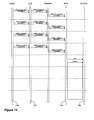
- Figure 8 is a sequence diagram showing the handling of a connect event according to the invention.
- the presentation format used in the diagram is attributable to Jacobson et al. ( Ivar Jacobson, Magnus Christerson, Patrick Jonsson and Gunnar Overgaard, Object-Oriented Software Engineering: A Use Case Driven Approach, Addison-Wesley, 1992 .).
- said sequence diagram describes the attachment of USB peripheral device (42) to remote extender (51b), and that remote extender (51b) is assigned to virtual port #2 (73b) on hub controller (63). It will be apparent to those skilled in the art that the same process can be applied to the attachment of any USB peripheral device or any USB hub to any remote extender and that further virtual ports can be assigned as required..
- connection sequence begins in section "A”.
- control logic (104) in USB peripheral device (42) drives a static J/K value on its USB data lines. Said static J/K value is detected by control logic (103) in remote extender (51b) and transmitted as a connect subaction across network (21) to local extender (50).
- Control logic (101) in local extender (50) updates the status of the corresponding virtual port (73b) and reports said change of status event to host computer (20).
- Control logic (100) in host computer (20) then requests the status of port #2, and control logic (101) in local extender (50) replies with a device connected indication.
- control logic (100) in host computer (20) issues a command to clear the change in connection status indicator belonging to port #2, and then requests confirmation that said command has been completed by issuing a further request for the status of port #2.
- Control logic (101) in local extender (50) clears said change in connection status indicator belonging to port #2, and reports that no further changes in status are outstanding. This operation completes the physical attachment sequence.
- control logic (100) in host computer (20) initiates a device reset sequence by generating a USB command to reset the device attached to port #2.
- Control logic (101) in local extender (50) translates said USB command into a reset subaction and transmits said reset subaction across network (21) to remote extender (51b).
- Control logic (103) in remote extender (51b) receives said transmitted reset subaction and drives a reset condition (SE0) on the data lines of downstream port (65b). After transmitting the reset condition for a period of time determined by the USB specification, said remote extender (51b) establishes the speed of operation of said USB peripheral device (42), and transmits said speed of operation as a speed subaction across network (21) to said local extender (50).
- Control logic (101) in local extender (50) updates the status of the corresponding virtual port and reports said change of status event to host computer (20).
- Control logic (100) in host computer (20) then requests the status of port #2, and control logic (101) in local extender (50) replies with a reset complete plus speed indication.
- control logic (100) in host computer (20) issues a command to clear the change in reset status indicator belonging to port #2, and then requests confirmation that said command has been completed by issuing a further request for the status of port #2.
- Control logic (101) in local extender (50) clears said change in reset status indicator belonging to virtual port #2 (73b), and reports that no further changes in status are outstanding. This operation completes the device reset sequence.
- FIG. 9 is a sequence diagram showing the handling of a disconnect event according to the invention.
- said sequence diagram describes the detachment of USB peripheral device (42) from remote extender (51b), and that remote extender (51b) is assigned to virtual port #2 (73b) on hub controller (63). It will be apparent to those skilled in the art that the same process can be applied to the detachment of any USB peripheral device or any USB hub from any remote extender and that further virtual ports can be assigned as required.
- control logic (104) in USB peripheral device (42) ceases to drive a static J/K value on its USB data lines. Said cessation of driving a static J/K value is detected by control logic (103) in remote extender (51b) and transmitted as a disconnect subaction across network (21) to local extender (50). Control logic (101) in local extender (50) updates the status of the corresponding virtual port and reports said change of status event to host computer (20).
- Control logic (100) in host computer (20) then requests the status of port #2, and control logic (101) in local extender (50) replies with a device disconnected indication.
- control logic (100) in host computer (20) issues a command to clear the change in connection status indicator belonging to port #2, and then issues a further command to clear the enabled status of port #2.
- Control logic (100) in host computer (20) then requests confirmation that said commands have been completed by issuing a further request for the status of port #2.
- Control logic (101) in local extender (50) clears said change in connection status indicator and said enabled status belonging to virtual port #2 (73b), and reports that no further changes in status are outstanding. This operation completes the physical detachment sequence.
- Figure 10 is a table recording the topology of a system configured according to the invention.
- the data presented in said table provides a method by which the example topology presented in Figure 2 can be mapped.
- the topology of the current invention illustrated in Figure 2 is required to emulate the topology of the prior art system illustrated in Figure 1 .
- the device column records the USB address of each device and hub contained in Figure 2 .
- the USB address is set identical to the numbering of the blocks in Figure 2 . It will be apparent to those skilled in the art that this association is not essential and that any USB address in the range 1 - 127 may be allocated by host computer (20).
- USB hub (31) is a physical unit and is allocated USB address 31.
- said USB hub is a virtual unit created by the combined operations of local extender (50), remote extenders (51a, 51b and 51c) and network (21). In order to emulate the operation of said physical USB hub (31), said virtual hub is also allocated USB address 31.
- the parent/address column records the USB address of the upstream hub to which a device or hub is connected.
- the parent/port column records the port number of the upstream hub to which a device or hub is connected.
- the child/port # columns record the USB address of the downstream device or hub connected to said port number.
- the number of child/port # columns shown in the table is four which enables a maximum of four remote extender units to be incorporated in the system. It will be apparent to those skilled in the art that this value is not unique and that currently any value in the range from 1 to 255 can be chosen, thereby enabling the maximum number of remote extender units to also fall within the range 1 to 255.
- the network address column records the network address of the network node to which a device or hub is directly connected.
- USB hub (31) which is connected to host computer (20) and acts as the root of the USB topology.
- said USB hub (31) is implemented as a virtual hub by the functions distributed in extenders (50, 51a, 51b and 51c) and in particular by hub controller (63) in local extender (50).
- Said USB hub (31) appears as device (31) in said table. Since USB hub (31) forms the root of the system it has no parent within the system and the value of its parent address and port number is set to null.
- the child entries for said USB hub (31) show that USB hub (32) is connected to its port #1, USB peripheral device (42) is connected to its port #2 and USB hub (33) is connected to its port #4.
- the network entry for said USB hub (31) shows that it is connected to network node (N0).
- N0 network node
- value (N0) is representational and that any other value may be used that is appropriate to the network chosen to provide data communications between said local and remote extenders. For example, if said data communications network is an Ethernet network then said network entry would be an Ethernet address. If said data communications network is an Internet network then said network entry would be an IP address.
- USB hub (34) shows that its parent is port #3 on USB hub (33), that USB peripheral device (44) is connected to its port #1, that USB peripheral device (45) is connected to its port #4, and that said USB hub (34) is not directly connected to network (21).
- the network address to be used for USB hub (34) is then found by tracing its connectivity back through its parent or parent's parent.
- USB hub (34) its parent is USB hub (33) and the network address of said USB hub (33) is (N3). In this manner, the chaining of USB hubs according to the USB Specification is accommodated by the present invention.
- USB peripheral device (42) shows that its parent is port #2 on USB hub (31) and that it is directly connected to network (21) at node (N2).
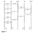
- Figure 11 is a sequence diagram showing the handling of a split asynchronous IN transaction according to the invention.
- Control logic (100) in host computer (20) initiates said transaction by issuing a first start-split IN command to local extender (50).
- Control logic (101) responds to said first start-split IN command by transmitting a negative response subaction to said host computer (20), and then forwards said first start-split IN command to remote extender (51b) across network (21).
- Control logic (101) continues to generate negative response subactions whenever a subsequent start-split IN command is received from host computer (20) and no response has been received from remote extender (51b).
- Control logic (103) in remote extender (51b) receives said first start-split IN command from network (21), converts said start-split IN command into a classic-speed IN command, and then forwards said classic-speed IN command to USB peripheral device (42). Also, control logic (103) in remote extender (51b) transmits a positive response subaction across network (21) to local extender (50) where said positive response subaction is stored in local memory.
- control logic (101) in local extender (50) retrieves said positive response subaction from local memory and forwards said retrieved positive response subaction to host computer (20).
- Control logic (100) in host computer (20) then issues a complete-split IN command and control logic (101) in local extender (50) replies with a not-yet response.
- control logic (104) in USB peripheral device (42) generates a classic-speed DATA0/1 response and forwards said response to remote extender (51b).
- Control logic (103) in remote extender (51b) generates a classic-speed confirm subaction and forwards said subaction to USB peripheral device (42).
- control logic (103) in remote extender (51b) forwards said DATA0/1 response across network (21) to local extender (50) where said DATA0/1 response subaction is stored in local memory.
- control logic (101) in local extender (50) retrieves said DATA0/1 response subaction from local memory and forwards said retrieved DATA0/1 response subaction to host computer (20).
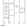
- Figure 12 is a sequence diagram showing the handling of a split asynchronous OUT transaction according to the invention.
- Control logic (100) in host computer (20) initiates said transaction by issuing a first start-split OUT/DATA0/1 command to local extender (50).
- Control logic (101) responds to said first start-split OUT/DATA0/1 command by transmitting a negative response subaction to said host computer (20), and then forwards said first start-split OUT/DATA0/1 command to remote extender (51b) across network (21).
- Control logic (101) continues to generate negative response subactions whenever a subsequent start-split OUT/DATA0/1command is received from host computer (20) and no response has been received from remote extender (51b).
- Control logic (103) in remote extender (51b) receives said first start-split OUT/DATA0/1 command from network (21), converts said start-split OUT/DATA0/1 command into a classic-speed OUT/DATA0/1 command, and then forwards said classic-speed OUT/DATA0/1 command to USB peripheral device (42). Also, control logic (103) in remote extender (51b) transmits a positive response subaction across network (21) to local extender (50) where said positive response subaction is stored in local memory.
- control logic (101) in local extender (50) retrieves said positive response subaction from local memory and forwards said retrieved positive response subaction to host computer (20).
- Control logic (100) in host computer (20) then issues a complete-split OUT command and control logic (101) in local extender (50) replies with a not-yet response.
- control logic (104) in USB peripheral device (42) generates a classic-speed positive response subaction and forwards said subaction to remote extender (51b).
- Control logic (103) in remote extender (51b) forwards said positive response subaction across network (21) to local extender (50) where said positive response subaction is stored in local memory.
- control logic (101) in local extender (50) retrieves said positive response subaction from local memory and forwards said retrieved positive response subaction to host computer (20).
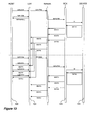
- Figure 13 is a sequence diagram showing the handling of a split isochronous IN transaction according to the invention.
- Control logic (100) in host computer (20) initiates said transaction by issuing a first start-split IN command to local extender (50).
- Control logic (101) in local extender (50) forwards said first start-split IN command to remote extender (51b) across network (21).
- Control logic (103) in remote extender (51b) receives said first start-split IN command from network (21), converts said start-split IN command into a classic-speed IN command, and then forwards said classic-speed IN command to USB peripheral device (42).
- control logic (100) in host computer (20) transmits a complete-split IN command to local extender (50) and control logic (101) in local extender (50) replies with a null-data response.
- Control logic (101) continues to generate null-data responses whenever a subsequent complete-split IN command is received from host computer (20) and a DATA0 response has not been received from remote extender (51b).
- control logic (104) in USB peripheral device (42) generates a classic-speed DATA0 response and forwards said response to remote extender (51b).
- Control logic (103) in remote extender (51b) converts said classic-speed DATA0 response into a sequence of high-speed MDATA/DATA0 responses and forwards said responses across network (21) to local extender (50) where said MDATA/DATA0 responses are stored in local memory.
- control logic (101) in local extender (50) retrieves said MDATA/DATA0 responses from local memory and forwards said retrieved MDATA/DATA0 responses to host computer (20).
- Figure 14 is a sequence diagram showing the handling of a split isochronous OUT transaction according to the invention.
- Control logic (100) in host computer (20) initiates said transaction by issuing a start-split-begin OUT/DATA0 command to local extender (50).
- Control logic (101) in local extender (50) forwards said start-split-begin OUT/DATA0 command to remote extender (51b) across network (21).
- Control logic (100) in host computer (20) continues said transaction by issuing one or more start-split-mid OUT/DATA0 commands to local extender (50).
- Control logic (101) in local extender (50) forwards each start-split-mid OUT/DATA0 command to remote extender (51b) across network (21).
- Control logic (100) in host computer (20) completes said transaction by issuing a start-split-end OUT/DATA0 command to local extender (50).
- Control logic (101) in local extender (50) forwards said start-split-end OUT/DATA0 command to remote extender (51b) across network (21).
- control logic (103) in remote extender (51b) receives said start-split-end OUT/DATA0 command, said control logic (103) assembles said start-split-begin OUT/DATA0 command, said one or more start-split-mid OUT/DATA0 commands and said start-split-end OUT/DATA0 command into a classic-speed OUT/DATA0 command and forwards said command to USB peripheral device (42).
Landscapes
- Engineering & Computer Science (AREA)
- General Engineering & Computer Science (AREA)
- Theoretical Computer Science (AREA)
- Computer Hardware Design (AREA)
- Physics & Mathematics (AREA)
- General Physics & Mathematics (AREA)
- Information Transfer Systems (AREA)
- Bus Control (AREA)
- Small-Scale Networks (AREA)
Claims (15)
- Verfahren zum Übertragen von Daten zwischen einem Hostcomputer (20) und einem oder mehreren USB-Peripheriegeräten (40, 41, 42, 43, 44, 45), wobei die USB-Peripheriegeräte in einem Datenkommunikationsnetzwerk verteilt sind und wobei die Übertragungsverzögerung über das Netzwerk größer als die normalerweise von der USB-Spezifikation erlaubte ist, wobei das Verfahren Folgendes umfasst: Verbinden eines Hostcomputers (20) mit einem lokalen Verlängerungsgerät (50), Verbinden des lokalen Verlängerungsgeräts mit einem oder mehreren entfernten Verlängerungsgeräten (51a, 51b, 51c) durch ein Datenkommunikationsnetzwerk (21) und Verbinden jedes der entfernten Verlängerungsgeräte (51a, 51b, 51c) mit einem oder mehreren USB-Peripheriegeräten (40, 41, 42, 43, 44, 45), wobei Signale zwischen dem Hostcomputer (20) und den USB-Peripheriegeräten (40, 41, 42, 43, 44, 45) in dem lokalen Verlängerer (50) und/oder den entfernten Verlängerern (51a, 51b, 51c) verarbeitet werden, um es so dem Hostcomputer (20) und den USB-Peripheriegeräten (40, 41, 42, 43, 44, 45) zu erlauben, bei Anwesenheit einer Gesamtlaufzeitverzögerung zu arbeiten, die größer als die normalerweise in der USB-Spezifikation erlaubte ist, und
wobei das Verfahren die Fähigkeit umfasst, den Anschluss eines USB-Peripheriegeräts an das System zu detektieren, die Ablösung eines USB-Peripheriegeräts zu detektieren oder die Netzwerkadresse einer USB-Funktion zu bestimmen, wobei die USB-Funktion ein USB-Hub oder ein USB-Peripheriegerät sein kann, und
wobei das Verfahren das Übertragen eines USB-Befehls von einem Hostcomputer (20) durch einen lokalen Verlängerer (50) zu einer einzigartigen Netzwerkadresse in einem Datenkommunikationsnetzwerk (21) gewährleistet, wobei das Verfahren durch Folgendes gekennzeichnet ist:i. in dem lokalen Verlängerer (50):a) Empfangen eines USB-Befehls von einem Hostcomputer (20);b) Extrahieren einer ersten USB-Adresse aus dem USB-Befehl;c) Verwenden der ersten USB-Adresse zum Zugriff auf einen ersten Datensatz in einer Tabelle, die USB-Adressen mit entsprechenden Netzwerkadressen in Beziehung setzt;d) Bestimmen, ob der erste Datensatz eine gültige Netzwerkadresse enthält;e) Extrahieren einer zweiten USB-Adresse aus dem ersten Datensatz, die den Upstream-USB-Hub identifiziert, durch den auf die erste USB-Adresse zugegriffen werden kann;f) Wiederholen der Schritte (c) bis (e) bis eine gültige Netzwerkadresse gefunden wird;g) Einkapseln des USB-Befehls in ein erstes Netzwerkpaket;h) Adressieren des ersten Netzwerkpakets an die gültige Netzwerkadresse;i) Übertragen des adressierten Netzwerkpakets zu dem Datenkommunikationsnetzwerk (21); undii. in einem entfernten Verlängerer (51a, 51b, 51c):j) Empfangen des übertragenen Netzwerkpakets von dem Datenkommunikationsnetzwerk (21);k) Extrahieren des USB-Befehls aus dem empfangenen Netzwerkpaket;l) Abliefern des extrahierten USB-Befehls an ein USB-Peripheriegerät (40, 41, 42, 43, 44, 45); oderiii. in dem entfernten Verlängerer (51a, 51b, 51c):undm) Empfangen einer USB-Antwort von einem USB-Peripheriegerät (40, 41, 42, 43, 44, 45);n) Einkapseln der USB-Antwort in ein zweites Netzwerkpaket;o) Adressieren des zweiten Netzwerkpakets an die Netzwerkadresse des lokalen Verlängerers (50);p) Übertragen des adressierten zweiten Netzwerkpakets zu dem Datenkommunikationsnetzwerk (21);iv. in dem lokalen Verlängerer (50):q) Empfangen des übertragenen zweiten Netzwerkpakets von dem Datenkommunikationsnetzwerk (21);r) Extrahieren der USB-Antwort aus dem übertragenen zweiten Netzwerkpaket; unds) Abliefern der extrahierten USB-Antwort an den USB-Hostcomputer (20). - Verfahren nach Anspruch 1, das die Fähigkeit umfasst, den Anschluss eines USB-Peripheriegeräts (40, 41, 42, 43, 44, 45) durch einen Hostcomputer (20) zu detektieren, wobei der Hostcomputer (20) und das USB-Peripheriegerät (40, 41, 42, 43, 44, 45) den Anforderungen der USB-Spezifikation genügen, durch einen lokalen Verlängerer (50) und einen entfernten Verlängerer (51a, 51b, 51c), wobei das Verfahren durch Folgendes gekennzeichnet ist:a) Detektieren eines Geräteanschlussereignisses in dem lokalen Verlängerer (50), Veranlassen, dass der entfernte Verlängerer (51a, 51b, 51c) ein Geräteverbindungssignal zu dem lokalen Verlängerer (50) sendet, und Veranlassen, dass der lokale Verlängerer (50) seine lokale Aufzeichnung der Änderung des Verbindungsstatus des USB-Peripheriegeräts und seine lokale Aufzeichnung des Verbunden-Status des USB-Peripheriegeräts aktualisiert;b) Empfangen einer Anforderung von dem Hostcomputer (20) von Gerätestatusänderungsinformationen in dem lokalen Verlängerer (50) und Veranlassen, dass der lokale Verlängerer (50) den Hostcomputer (20) informiert, dass sich der Status des USB-Peripheriegeräts (40, 41, 42, 43, 44, 45) geändert hat;c) Empfangen einer Anforderung von dem Hostcomputer (20) des Status des USB-Peripheriegeräts (40, 41, 42, 43, 44, 45) in dem lokalen Verlängerer (50) und Veranlassen, dass der lokale Verlängerer (50) die lokale Aufzeichnung der Änderung des Verbindungsstatus und die lokale Aufzeichnung des Verbunden-Status dem Hostcomputer (20) bereitstellt;d) Empfangen einer Anforderung von dem Hostcomputer (20) in dem lokalen Verlängerer (50), die Änderung der Verbindungsstatusinformationen zu löschen, und Veranlassen, dass der lokale Verlängerer (50) die lokale Aufzeichnung der Änderung von Verbindungsstatusinformationen löscht;e) Empfangen einer weiteren Anforderung von dem Hostcomputer (20) des Status des USB-Peripheriegeräts (40, 41, 42, 43, 44, 45) in dem lokalen Verlängerer (50) und Veranlassen, dass der lokale Verlängerer (50) die gelöschte lokale Aufzeichnung der Änderung des Verbindungsstatus und die lokale Aufzeichnung des Verbunden-Status dem Hostcomputer (20) bereitstellt;f) Empfangen eines Befehls von dem Hostcomputer (20) in dem lokalen Verlängerer (50), das USB-Peripheriegerät (40, 41, 42, 43, 44, 45) rückzusetzen, Veranlassen, dass der lokale Verlängerer (50) ein Rücksetzsignal zu dem entfernten Verlängerer (51a, 51b, 51c) sendet, und dann Veranlassen, dass der entfernte Verlängerer (51a, 51b, 51c) ein physisches Rücksetzen an dem USB-Peripheriegerät (40, 41, 42, 43, 44, 45) ausführt;g) Detektieren der Übertragungsgeschwindigkeit des USB-Peripheriegeräts (40, 41, 42, 43, 44, 45) in dem entfernten Verlängerer (51a, 51b, 51c), Veranlassen, dass der entfernte Verlängerer (51a, 51b, 51c) ein Geschwindigkeitssignal zu dem lokalen Verlängerer (50) sendet, und dann Veranlassen, dass der lokale Verlängerer (50) seine lokale Aufzeichnung der Übertragungsgeschwindigkeit des USB-Peripheriegeräts (40, 41, 42, 43, 44, 45) und seine lokale Aufzeichnung der Änderung des Rücksetzstatus des USB-Peripheriegeräts (40, 41, 42, 43, 44, 45) aktualisiert;h) Empfangen einer weiteren Anforderung von dem Hostcomputer (20) von Gerätestatusänderungsinformationen in dem lokalen Verlängerer (50) und Veranlassen, dass der lokale Verlängerer (50) den Hostcomputer (20) informiert, dass sich der Status des USB-Peripheriegeräts (40, 41, 42, 43, 44, 45) geändert hat;i) Empfangen noch einer weiteren Anforderung von dem Hostcomputer (20) des Status des USB-Peripheriegeräts (40, 41, 42, 43, 44, 45) in dem lokalen Verlängerer (50) und Veranlassen, dass der lokale Verlängerer (50) die lokale Aufzeichnung der Übertragungsgeschwindigkeit des USB-Peripheriegeräts (40, 41, 42, 43, 44, 45) und seine lokale Aufzeichnung der Änderung des Rücksetzstatus des USB-Peripheriegeräts (40, 41, 42, 43, 44, 45) dem Hostcomputer (20) bereitstellt;j) Empfangen einer Anforderung von dem Hostcomputer (20) in dem lokalen Verlängerer (50), die Änderung der Rücksetzstatusinformationen zu löschen, und Veranlassen, dass der lokale Verlängerer (50) die lokale Aufzeichnung der Änderung der Rücksetzstatusinformationen löscht; undk) Empfangen einer Anforderung von dem Hostcomputer (20) des Status des USB-Peripheriegeräts (40, 41, 42, 43, 44, 45) in dem lokalen Verlängerer (50) und Veranlassen, dass der lokale Verlängerer (50) die gelöschte lokale Aufzeichnung der Änderung des Rücksetzstatus dem Hostcomputer (20) bereitstellt.
- Verfahren nach Anspruch 1, das die Fähigkeit umfasst, die Ablösung eines USB-Peripheriegeräts (40, 41, 42, 43, 44, 45) durch einen Hostcomputer (20) zu detektieren, wobei der Hostcomputer (20) und das USB-Peripheriegerät (40, 41, 42, 43, 44, 45) den Anforderungen der USB-Spezifikation genügen, durch einen lokalen Verlängerer (50) und einen entfernten Verlängerer (51a, 51b, 51c), wobei das Verfahren durch Folgendes gekennzeichnet ist:a) Detektieren eines Geräteablösungsereignisses in dem entfernten Verlängerer (51a, 51b, 51c), Veranlassen, dass der entfernte Verlängerer (51a, 51b, 51c) ein Gerätetrennungssignal zu dem lokalen Verlängerer (50) sendet, und dann Veranlassen, dass der lokale Verlängerer (50) seine lokale Aufzeichnung der Änderung des Verbindungsstatus des USB-Peripheriegeräts (40, 41, 42, 43, 44, 45) und seine lokale Aufzeichnung des Verbunden-Status des USB-Peripheriegeräts (40, 41, 42, 43, 44, 45) aktualisiert;b) Empfangen einer Anforderung von dem Hostcomputer (20) von Gerätestatusänderungsinformationen in dem lokalen Verlängerer (50) und Veranlassen, dass der lokale Verlängerer (50) den Hostcomputer (20) informiert, dass sich der Status des USB-Peripheriegeräts (40, 41, 42, 43, 44, 45) geändert hat;c) Empfangen einer Anforderung von dem Hostcomputer (20) des Status des USB-Peripheriegeräts (40, 41, 42, 43, 44, 45) in dem lokalen Verlängerer (50) und Veranlassen, dass der lokale Verlängerer (50) die lokale Aufzeichnung der Änderung des Verbindungsstatus und die lokale Aufzeichnung des Verbunden-Status dem Hostcomputer (20) bereitstellt;d) Empfangen einer Anforderung von dem Hostcomputer (20) in dem lokalen Verlängerer (50), die Änderung von Verbindungsstatusinformationen zu löschen, und Veranlassen, dass der lokale Verlängerer (50) die lokale Aufzeichnung der Änderung von Verbindungsstatusinformationen löscht;e) Empfangen einer Anforderung von dem Hostcomputer (20) in dem lokalen Verlängerer (50), Freigegeben-Statusinformationen des USB-Peripheriegeräts (40, 41, 42, 43, 44, 45) zu löschen, und Veranlassen, dass der lokale Verlängerer (50) seine lokale Aufzeichnung von Freigegeben-Statusinformationen löscht; undf) Empfangen einer weiteren Anforderung von dem Hostcomputer (20) des Status des USB-Peripheriegeräts (40, 41, 42, 43, 44, 45) in dem lokalen Verlängerer (50) und Veranlassen, dass der lokale Verlängerer (50) die gelöschte lokale Aufzeichnung der Änderung des Verbindungsstatus und die gelöschte lokale Aufzeichnung des Freigegeben-Status dem Hostcomputer (20) bereitstellt.
- Verfahren nach Anspruch 1, das die Fähigkeit umfasst, die Netzwerkadresse einer USB-Funktion zu bestimmen, wobei die USB-Funktion ein USB-Hub (32, 33, 34) oder ein USB-Peripheriegerät (40, 41, 42, 43, 44, 45) sein kann und wobei mehrere der USB-Funktionen in einem Datenkommunikationsnetzwerk (21) verteilt sein können und wobei durch einen Hostcomputer (20) an jede USB-Funktion eine USB-Adresse vergeben wird, wobei das Verfahren durch Folgendes gekennzeichnet ist:a) Aufbauen der Datenaufzeichnung in der Tabelle für jede direkt oder indirekt mit dem Netzwerk (21) verbundene erste USB-Funktion und Identifizieren jeder Aufzeichnung durch eine einzigartige USB-Adresse, die dynamisch durch den Hostcomputer (20) zugewiesen wird;b) Aufzeichnen der USB-Adresse des Upstream-USB-Hub, mit dem die erste USB-Funktion verbunden ist, in der Datenaufzeichnung;c) Aufzeichnen der Portnummer des Upstream-USB-Hub (32, 33, 34), mit dem die erste USB-Funktion verbunden ist, in der Datenaufzeichnung;d) Aufzeichnen der USB-Adresse jeder direkt mit der ersten USB-Funktion verbundenen Downstream-USB-Funktion in der Datenaufzeichnung;e) Aufzeichnen der Portnummer der ersten USB-Funktion, mit der jede Downstream-USB-Funktion verbunden ist, in der Datenaufzeichnung; undf) Aufzeichnen der Netzwerkadresse, die der ersten USB-Funktion zugewiesen wird.
- Verfahren zum Übertragen von Daten zwischen einem Hostcomputer (20) und einem oder mehreren USB-Peripheriegeräten (40, 41, 42, 43, 44, 45) nach Anspruch 1, wobei das Verfahren das Durchführen asynchroner Datentransaktionen zwischen einem Hostcomputer (20) und einem USB-Peripheriegerät (40, 41, 42, 43, 44, 45) ermöglicht, wobei der Hostcomputer (20) mit hoher Geschwindigkeit arbeitet und das USB-Peripheriegerät (40, 41, 42, 43, 44, 45) mit klassischer Geschwindigkeit (voller Geschwindigkeit oder niedriger Geschwindigkeit) arbeitet und wobei sich die Daten in einer Richtung von Gerät zu Host ausbreiten, durch den entfernten Verlängerer (51a, 51b, 51c) und den lokalen Verlängerer (50), wobei das Verfahren durch Folgendes gekennzeichnet ist:a) Empfangen einer ersten Anforderung von dem Hostcomputer (20) des Starts einer aufgeteilten Datentransfersitzung in dem lokalen Verlängerer (50), Veranlassen, dass der lokale Verlängerer (50) die erste Anforderung über ein Netzwerk (21) zu dem entfernten Verlängerer (51a, 51b, 51c) weiterleitet, und dann Veranlassen, dass der lokale Verlängerer (50) eine Negativ-Bestätigungsantwort an den Hostcomputer (20) erzeugt;b) Empfangen einer nachfolgenden Anforderung von dem Hostcomputer (20) des Starts einer aufgeteilten Datentransfersitzung in dem lokalen Verlängerer (50) und Veranlassen, dass der lokale Verlängerer (50) weiter Negativ-Bestätigungsantworten an den Hostcomputer (20) erzeugt, bis der lokale Verlängerer (50) eine Antwort auf die weitergeleitete erste Anforderung von dem entfernten Verlängerer (51a, 51b, 51c) empfängt;c) Empfangen der weitergeleiteten ersten Anforderung des Starts einer aufgeteilten Datentransfersitzung in dem entfernten Verlängerer (51a, 51b, 51c), Veranlassen, dass der entfernte Verlängerer (51a, 51b, 51c) die weitergeleitete Anforderung des Starts einer aufgeteilten Datentransfersitzung in eine Anforderung klassischer Geschwindigkeit von Datentransfer umsetzt, und Veranlassen, dass der entfernte Verlängerer (51a, 51b, 51c) die Anforderung klassischer Geschwindigkeit von Datentransfer zu dem USB-Peripheriegerät (40, 41, 42, 43, 44, 45) weiterleitet;d) Erzeugen einer Positiv-Bestätigungsantwort in dem entfernten Verlängerer (51a, 51b, 51c) und Weiterleiten der Positiv-Bestätigungsantwort über ein Netzwerk (21) zu dem lokalen Verlängerer (50);e) Empfangen der weitergeleiteten Positiv-Bestätigungsantwort in dem lokalen Verlängerer (50) und Veranlassen, dass der lokale Verlängerer (50) die weitergeleitete Positiv-Bestätigungsantwort in lokalem Speicher speichert;f) Empfangen einer weiteren Anforderung von dem Hostcomputer (20) des Starts einer aufgeteilten Datentransfersitzung in dem lokalen Verlängerer (50), Veranlassen, dass der lokale Verlängerer (50) aus lokalem Speicher die weitergeleitete Positiv-Bestätigungsantwort abruft, und dann Veranlassen, dass der lokale Verlängerer (50) die abgerufene Positiv-Bestätigungsantwort zu dem Hostcomputer (20) weiterleitet;g) Empfangen einer Datentransferantwort von dem USB-Peripheriegerät (40, 41, 42, 43, 44, 45) in dem entfernten Verlängerer (51a, 51b, 51c) und Veranlassen, dass der entfernte Verlängerer (51a, 51b, 51c) eine Positiv-Bestätigungsantwort an das USB-Peripheriegerät (40, 41, 42, 43, 44, 45) erzeugt, und dann Veranlassen, dass der entfernte Verlängerer (51a, 51b, 51c) die Datentransferantwort über ein Netzwerk (21) zu dem lokalen Verlängerer (50) weiterleitet;h) Empfangen einer ersten Anforderung des Abschlusses einer aufgeteilten Datentransfersitzung in dem lokalen Verlängerer (50), Veranlassen, dass der lokale Verlängerer (50) lokale Speicher auf die Abwesenheit einer Datentransferantwort prüft, und dann Veranlassen, dass der lokale Verlängerer (50) eine Noch-Nicht-Bestätigung an den Hostcomputer (20) erzeugt;i) Empfangen der weitergeleiteten Datentransferantwort von dem entfernten Verlängerer (51a, 51b, 51c) in dem lokalen Verlängerer (50) und Veranlassen, dass der lokale Verlängerer (51a, 51b, 51c) die weitergeleitete Datentransferantwort in lokalem Speicher speichert; undj) Empfangen einer weiteren Anforderung des Abschlusses einer aufgeteilten Datentransfersitzung in dem lokalen Verlängerer (50), Veranlassen, dass der lokale Verlängerer (50) aus lokalem Speicher die weitergeleitete Datentransferantwort abruft, und dann Veranlassen, dass der lokale Verlängerer (50) die abgerufene Datentransferantwort zu dem Hostcomputer (20) weiterleitet.
- Verfahren zum Übertragen von Daten zwischen einem Hostcomputer (20) und einem oder mehreren USB-Peripheriegeräten (40, 41, 42, 43, 44, 45) nach Anspruch 1, wobei das Verfahren das Durchführen von asynchronen Datentransaktionen zwischen einem Hostcomputer (20) und einem USB-Peripheriegerät (40, 41, 42, 43, 44, 45) ermöglicht, wobei der Hostcomputer (20) mit hoher Geschwindigkeit arbeitet und das USB-Peripheriegerät (40, 41, 42, 43, 44, 45) mit klassischer Geschwindigkeit (voller Geschwindigkeit oder niedriger Geschwindigkeit) arbeitet und wobei sich die Daten in einer Richtung von Host zu Gerät ausbreiten, durch den lokalen Verlängerer (40) und den entfernten Verlängerer (51a, 51b, 51c), wobei das Verfahren durch Folgendes gekennzeichnet ist:a) Empfangen einer ersten Benachrichtigung von dem Hostcomputer (20) für den Start einer aufgeteilten Datentransfersitzung in dem lokalen Verlängerer (50), Veranlassen, dass der lokale Verlängerer (50) die erste Benachrichtigung über ein Netzwerk (21) zu dem entfernten Verlängerer (51a, 51b, 51c) weiterleitet, und dann Veranlassen, dass der lokale Verlängerer (50) eine Negativ-Bestätigungsantwort an den Hostcomputer (20) erzeugt;b) Empfangen einer nachfolgenden Benachrichtigung von dem Hostcomputer (20) für den Start einer aufgeteilten Datentransfersitzung in dem lokalen Verlängerer (50) und Veranlassen, dass der lokale Verlängerer (50) weiter Negativ-Bestätigungsantworten an den Hostcomputer (20) erzeugt, bis der lokale Verlängerer (50) eine Antwort auf die weitergeleitete erste Benachrichtigung von dem entfernten Verlängerer (51a, 51b, 51c) empfängt;c) Empfangen der weitergeleiteten ersten Benachrichtigung für den Start einer aufgeteilten Datentransfersitzung in dem entfernten Verlängerer (51a, 51b, 51c), Veranlassen, dass der entfernte Verlängerer (51a, 51b, 51c) die weitergeleitete Benachrichtigung für den Start einer aufgeteilten Datentransfersitzung in eine Benachrichtigung klassischer Geschwindigkeit für Datentransfer umsetzt, und dann Veranlassen, dass der entfernte Verlängerer (51a, 51b, 51c) die Benachrichtigung klassischer Geschwindigkeit für Datentransfer zu dem USB-Peripheriegerät (40, 41, 42, 43, 44, 45) weiterleitet;d) Erzeugen einer Positiv-Bestätigungsantwort in dem entfernten Verlängerer (51a, 51b, 51c) und Weiterleiten der Positiv-Bestätigungsantwort über ein Netzwerk (21) zu dem lokalen Verlängerer (50);e) Empfangen der weitergeleiteten Positiv-Bestätigungsantwort in dem lokalen Verlängerer (50) und Veranlassen, dass der lokale Verlängerer (50) die weitergeleitete Positiv-Bestätigungsantwort in lokalem Speicher speichert;f) Empfangen einer weiteren Benachrichtigung von dem Hostcomputer (20) für den Start einer aufgeteilten Datentransfersitzung in dem lokalen Verlängerer (50), Veranlassen, dass der lokale Verlängerer (50) aus lokalem Speicher die weitergeleitete Positiv-Bestätigungsantwort abruft, und dann Veranlassen, dass der lokale Verlängerer (50) die abgerufene Positiv-Bestätigungsantwort zu dem Hostcomputer (20) weiterleitet;g) Empfangen einer Positiv-Bestätigungsantwort von dem USB-Peripheriegerät (40, 41, 42, 43, 44, 45) in dem lokalen Verlängerer (50) und Veranlassen, dass der entfernte Verlängerer (51a, 51b, 51c) die Positiv-Bestätigungsantwort über ein Netzwerk (21) zu dem lokalen Verlängerer (50) weiterleitet;h) Empfangen einer ersten Anforderung des Abschlusses einer aufgeteilten Datentransfersitzung in dem lokalen Verlängerer (50), Veranlassen, dass der lokale Verlängerer (50) lokalen Speicher auf die Abwesenheit einer Positiv-Bestätigungsantwort prüft, und dann Veranlassen, dass der lokale Verlängerer (50) eine Noch-Nicht-Bestätigung an den Hostcomputer (20) erzeugt;i) Empfangen der weitergeleiteten Positiv-Bestätigungsantwort von dem entfernten Verlängerer (51a, 51b, 51c) in dem lokalen Verlängerer (50) und Veranlassen, dass der lokale Verlängerer (50) die weitergeleitete Positiv-Bestätigungsantwort in lokalem Speicher speichert; undj) Empfangen einer weiteren Anforderung des Abschlusses einer aufgeteilten Datentransfersitzung in dem lokalen Verlängerer (50), Veranlassen, dass der lokale Verlängerer (50) aus lokalem Speicher die weitergeleitete Positiv-Bestätigungsantwort abruft, und dann Veranlassen, dass der lokale Verlängerer (50) die abgerufene Positiv-Bestätigungsantwort zu dem Hostcomputer (20) weiterleitet.
- Verfahren zum Übertragen von Daten zwischen einem Hostcomputer (20) und einem oder mehreren USB-Peripheriegeräten (40, 41, 42, 43, 44, 45) nach Anspruch 1, wobei das Verfahren das Durchführen von isochronen Datentransaktionen zwischen einem Hostcomputer (20) und einem USB-Peripheriegerät (40, 41, 42, 43, 44, 45) ermöglicht, wobei der Hostcomputer (20) mit hoher Geschwindigkeit arbeitet und das USB-Peripheriegerät (40, 41, 42, 43, 44, 45) mit klassischer Geschwindigkeit (voller Geschwindigkeit oder niedriger Geschwindigkeit) arbeitet und wobei sich die Daten in einer Richtung von Gerät zu Host ausbreiten, durch den entfernten Verlängerer (51a, 51b, 51c) und den lokalen Verlängerer (50), wobei das Verfahren durch Folgendes gekennzeichnet ist:a) Empfangen einer ersten Anforderung von dem Hostcomputer (20) des Starts einer aufgeteilten Datentransfersitzung in dem lokalen Verlängerer (50) und Veranlassen, dass der lokale Verlängerer (50) die erste Anforderung des Starts der aufgeteilten Datentransfersitzung über ein Netzwerk (21) zu dem entfernten Verlängerer (51a, 51b, 51c) weiterleitet;b) Empfangen einer ersten Anforderung des Abschlusses einer aufgeteilten Datentransfersitzung in dem lokalen Verlängerer (50), Veranlassen, dass der lokale Verlängerer (50) lokalen Speicher auf die Abwesenheit einer abgeschlossenen Sequenz von Antworten des aufgeteilten Datentransfers prüft, und dann Veranlassen, dass der lokale Verlängerer (50) eine Null-Datenantwort an den Hostcomputer (20) erzeugt;c) Empfangen der weitergeleiteten ersten Anforderung des Starts einer aufgeteilten Datentransfersitzung in dem entfernten Verlängerer (51a, 51b, 51c), Veranlassen, dass der entfernte Verlängerer (51a, 51b, 51c) die weitergeleitete Anforderung des Starts einer aufgeteilten Datentransfersitzung in eine Anforderung klassischer Geschwindigkeit von Datentransfer umsetzt, und dann Veranlassen, dass der entfernte Verlängerer (51a, 51b, 51c) die Anforderung klassischer Geschwindigkeit von Datentransfer zu dem USB-Peripheriegerät (40, 41, 42, 43, 44, 45) weiterleitet;d) Empfangen einer Datentransferantwort von dem USB-Peripheriegerät (40, 41, 42, 43, 44, 45) in dem entfernten Verlängerer (51a, 51b, 51c) und Veranlassen, dass der entfernte Verlängerer (51a, 51b, 51c) die empfangene Datentransferantwort in eine Sequenz von Antworten des aufgeteilten Datentransfers umsetzt, und dann Veranlassen, dass der entfernte Verlängerer (51a, 51b, 51c) die Sequenz von Antworten des aufgeteilten Datentransfers über ein Netzwerk (21) zu dem lokalen Verlängerer (50) weiterleitet;e) Empfangen der weitergeleiteten Sequenz von Antworten des aufgeteilten Datentransfers von dem entfernten Verlängerer (51a, 51b, 51c) in dem lokalen Verlängerer (50) und Veranlassen, dass der lokale Verlängerer (50) die weitergeleitete Sequenz von Antworten des aufgeteilten Datentransfers in lokalem Speicher speichert;f) Empfangen einer nachfolgenden Anforderung von dem Hostcomputer (20) des Starts einer aufgeteilten Datentransfersitzung in dem lokalen Verlängerer (50) und Veranlassen, dass der lokale Verlängerer (50) die nachfolgende Anforderung über ein Netzwerk (21) zu dem entfernten Verlängerer (51a, 51b, 51c) weiterleitet; undg) Empfangen einer Sequenz nachfolgender Anforderungen des Abschlusses einer aufgeteilten Datentransfersitzung in dem lokalen Verlängerer (50), Veranlassen, dass der lokale Verlängerer (50) lokalen Speicher auf die Anwesenheit einer vollständigen Sequenz von Antworten des aufgeteilten Datentransfers prüft, und dann Veranlassen, dass der lokale Verlängerer (50) die Sequenz von Antworten aufgeteilter Daten aus Speicher abruft und die Sequenz von Antworten aufgeteilter Daten zu dem Hostcomputer (20) weiterleitet.
- Verfahren zum Übertragen von Daten zwischen einem Hostcomputer (20) und einem oder mehreren USB-Peripheriegeräten (40, 41, 42, 43, 44, 45) nach Anspruch 1, wobei das Verfahren das Durchführen von isochronen Datentransaktionen zwischen einem Hostcomputer (20) und einem USB-Peripheriegerät (40, 41, 42, 43, 44, 45) ermöglicht, wobei der Hostcomputer (20) mit hoher Geschwindigkeit arbeitet und das USB-Peripheriegerät (40, 41, 42, 43, 44, 45) mit klassischer Geschwindigkeit (voller Geschwindigkeit oder niedriger Geschwindigkeit) arbeitet und wobei sich die Daten in einer Richtung von Host zu Gerät ausbreiten, durch den lokalen Verlängerer (50) und den entfernten Verlängerer (51a, 51b, 51c), wobei das Verfahren durch Folgendes gekennzeichnet ist:a) Empfangen einer Benachrichtigung von dem Hostcomputer (20) für den Start einer aufgeteilten Datentransfersitzung in dem lokalen Verlängerer (50), Veranlassen, dass der lokale Verlängerer (50) die Benachrichtigung für den Start einer aufgeteilten Datentransfersitzung über ein Netzwerk (21) zu dem entfernten Verlängerer (51a, 51b, 51c) weiterleitet, und dann Veranlassen, dass der entfernte Verlängerer (50) die Benachrichtigung für den Start einer aufgeteilten Datentransfersitzung in lokalem Speicher speichert;b) Empfangen einer ersten Benachrichtigung von dem Hostcomputer (20) für die Fortsetzung einer aufgeteilten Datentransfersitzung in dem lokalen Verlängerer (50), Veranlassen, dass der lokale Verlängerer (50) die erste Benachrichtigung für die Fortsetzung einer aufgeteilten Datentransfersitzung über ein Netzwerk (21) zu dem entfernten Verlängerer (51a, 51b, 51c) weiterleitet, und dann Veranlassen, dass der entfernte Verlängerer (51a, 51b, 51c) die erste Benachrichtigung für die Fortsetzung einer aufgeteilten Datentransfersitzung in lokalem Speicher gespeichert;c) Empfangen einer weiteren Benachrichtigung von dem Hostcomputer (20) für die Fortsetzung einer aufgeteilten Datentransfersitzung in dem lokalen Verlängerer (50), Veranlassen, dass der lokale Verlängerer (50) die weitere Benachrichtigung für die Fortsetzung einer aufgeteilten Datentransfersitzung über ein Netzwerk (21) zu dem entfernten Verlängerer (51a, 51b, 51c) weiterleitet, und dann Veranlassen, dass der entfernte Verlängerer (51a, 51b, 51c) die weitere Benachrichtigung für die Fortsetzung einer aufgeteilten Datentransfersitzung in lokalem Speicher speichert;d) Empfangen einer Benachrichtigung von dem Hostcomputer (20) für den Abschluss einer aufgeteilten Datentransfersitzung in dem lokalen Verlängerer (50), Veranlassen, dass der lokale Verlängerer (50) die Benachrichtigung für den Abschluss einer aufgeteilten Datentransfersitzung über ein Netzwerk (21) zu dem entfernten Verlängerer (51a, 51b, 51c) weiterleitet, und dann Veranlassen, dass der entfernte Verlängerer (51a, 51b, 51c) die Benachrichtigung für den Abschluss einer aufgeteilten Datentransfersitzung in lokalem Speicher gespeichert;e) Zusammenstellen der gespeicherten Benachrichtigung für den Start eines aufgeteilten Datentransfers, der gespeicherten ersten Benachrichtigung für die Fortsetzung eines aufgeteilten Datentransfers, der gespeicherten weiteren Benachrichtigung für die Fortsetzung eines aufgeteilten Datentransfers und der gespeicherten Benachrichtigung für den Abschluss einer aufgeteilten Datentransfersitzung in dem entfernten Verlängerer (51a, 51b, 51c) zu einer Benachrichtigung klassischer Geschwindigkeit von Datentransfer; undf) Veranlassen, dass der entfernte Verlängerer (51a, 51b, 51c) die Benachrichtigung klassischer Geschwindigkeit von Datentransfer zu dem USB-Peripheriegerät (40, 41, 42, 43, 44, 45) weiterleitet.
- Verfahren nach einem der vorhergehenden Ansprüche, wobei das Verfahren über ein Datenkommunikationsnetzwerk (21) operiert, in dem die Gesamtlaufzeitverzögerung 1 Mikrosekunde übersteigt.
- Computersystem zum Übertragen von Daten zwischen einem Hostcomputer (20) und einem oder mehreren USB-Peripheriegeräten (40, 41, 42, 43, 44, 45), wobei die USB-Peripheriegeräte (40, 41, 42, 43, 44, 45) in einem Datenkommunikationsnetzwerk (21) verteilt sein können und wobei die Übertragungsverzögerung über das Netzwerk (21) größer als die ist, die normalerweise von der USB-Spezifikation erlaubt wird, wobei das Computersystem durch Folgendes gekennzeichnet ist:a) einen Hostcomputer (20) zum Erzeugen und Annehmen von USB-Subaktionen;b) ein oder mehrere USB-Peripheriegeräte (40, 41, 42, 43, 44, 45) mit der Fähigkeit, auf durch den Hostcomputer (20) eingeleitete USB-Subaktionen zu reagieren;c) eine mit dem Hostcomputer (20) verbundene lokale Verlängerereinheit (50) zum Weiterleiten von USB-Subaktionen von dem Hostcomputer (20) zu einem Datenkommunikationsnetzwerk (21) und zum Weiterleiten von aus dem Datenkommunikationsnetzwerk (21) empfangenen Subaktionen zu dem Hostcomputer (20);d) eine oder mehrere entfernte Verlängerereinheiten (51a, 51b, 51c), die jeweils mit einem oder mehreren USB-Peripheriegeräten (40, 41, 42, 43, 44, 45) verbunden sind, zum Weiterleiten von aus dem Datenkommunikationsnetzwerk (21) empfangenen USB-Subaktionen zu den USB-Peripheriegeräten (40, 41, 42, 43, 44, 45) und zum Weiterleiten von aus den USB-Peripheriegeräten (40, 41, 42, 43, 44, 45) empfangenen USB-Subaktionen zu dem Datenkommunikationsnetzwerk (21);e) ein Datenkommunikationsnetzwerk (21) zum Weiterleiten von USB-Subaktionen von der lokalen Verlängerereinheit (50) zu den entfernten Verlängerereinheiten (51a, 51b, 51c) und zum Weiterleiten von USB-Subaktionen von den entfernten Verlängerereinheiten (51a, 51b, 51c) zu der lokalen Verlängerereinheit (50);f) Mittel in der lokalen Verlängerereinheit zum Weiterleiten einer von dem Hostcomputer (20) empfangenen USB-Subaktion zu der entfernten Verlängerereinheit (51a, 51b, 51c) über das Datenkommunikationsnetzwerk (21) und zum Erzeugen und Senden einer erzeugten USB-Subaktion zu dem Hostcomputer (20);g) Mittel in der entfernten Verlängerereinheit zum Weiterleiten der von dem Hostcomputer (20) empfangenen USB-Subaktion zu einem oder mehreren USB-Peripheriegeräten (40, 41, 42, 43, 44, 45) und zum Empfangen einer von einem USB-Peripheriegerät (40, 41, 42, 43, 44, 45) empfangenen Subaktion;h) Mittel in der entfernten Verlängerereinheit zum Weiterleiten der von einem USB-Peripheriegerät (40, 41, 42, 43, 44, 45) empfangenen Subaktion zu der lokalen Verlängerereinheit (50) über das Datenkommunikationsnetzwerk (21);i) Mittel in der entfernten Verlängerereinheit zum Erzeugen einer USB-Subaktion zur Bestätigung einer von einem USB-Peripheriegerät (40, 41, 42, 43, 44, 45) empfangenen USB-Subaktion und Senden der erzeugten Bestätigungs-USB-Subaktion zu dem USB-Peripheriegerät (40, 41, 42, 43, 44, 45);j) Mittel in der entfernten Verlängerereinheit zum Erzeugen einer USB-Subaktion als Reaktion auf eine von dem Hostcomputer (20) empfangene USB-Subaktion und Senden der erzeugten Antwort-USB-Subaktion zu der lokalen Verlängerereinheit (50);k) Mittel in der lokalen Verlängerereinheit zum Empfangen und Identifizieren, wann eine Sequenz von ankommenden USB-Subaktionen, die von der entfernten Verlängerereinheit (51a, 51b, 51c) über das Datenkommunikationsnetzwerk (21) empfangen wird, mit einer gemeinsamen abgehenden USB-Subaktion in Beziehung steht;l) Mittel in der lokalen Verlängerereinheit zum Speichern einer ankommenden USB-Subaktion von der entfernten Verlängerereinheit (51a, 51b, 51c), bis eine solche ankommende USB-Subaktion wieder von dem Hostcomputer (20) angefordert wird; undm) Mittel in der lokalen Verlängerereinheit zum Weiterleiten der gespeicherten USB-Subaktion zu dem Hostcomputer (20); und optionali) Mittel in der entfernten Verlängerereinheit zum Zusammenstellen einer Sequenz von USB-Subaktionen zu einer atomischen USB-Subaktion und vorzugsweise Senden der atomischen USB-Subaktion zu dem USB-Peripheriegerät (40, 41, 42, 43, 44, 45); undii) Mittel in der entfernten Verlängerereinheit zum Auseinandernehmen einer atomischen USB-Subaktion in eine Sequenz von diskreten USB-Subaktionen und vorzugsweise Senden der Sequenz von diskreten USB-Subaktionen zu der lokalen Verlängerereinheit (50).
- Computersystem nach Anspruch 10, wobei der Hostcomputer (20) ein Computer ist, der die USB-Spezifikation unterstützt, und wobei die Gesamtlaufzeitverzögerung eine Übertragungsverzögerung und eine Umlaufzeitverzögerung umfasst und wobei die Übertragungsverzögerung zwischen dem Hostcomputer (20) und dem USB-Peripheriegerät (40, 41, 42, 43, 44, 45) 1 Mikrosekunde übersteigt.
- Lokale Verlängerervorrichtung (50) zur Verwendung beim Übertragen von USB-Verkehr zwischen einem Hostcomputer (20) und einem Datenkommunikationsnetzwerk (21) in einem Computersystem nach Anspruch 10, wobei der USB-Verkehr an mehrere USB-Peripheriegeräte adressiert werden kann, wobei die Vorrichtung durch Folgendes gekennzeichnet ist:a) einen USB-Sender/-Empfänger (81) zur Verbindung mit dem Hostcomputer (20);b) einen upstream weisenden Port (60) zum Steuern des USB-Senders/-Empfängers (81);c) eine lokale Repeatereinheit (71) zum Regenerieren von die Vorrichtung durchlaufenden USB-Subaktionen und zum Switchen von USB-Subaktionen zwischen den Komponenten der Vorrichtung;d) eine Speichereinheit (82) zum Speichern von USB-Subaktionen während der Verarbeitung durch die Vorrichtung;e) eine lokale Routereinheit (72) zum Bereitstellen einer Netzwerkadresse für USB-Subaktionen, die sich in einer Downstream-Richtung von Host zu Netzwerk bewegen;f) einen Netzwerksender/-Empfänger (84) zur Verbindung mit dem Datenkommunikationsnetzwerk (21);g) eine Hub-Steuerungseinheit (69) zum Reagieren auf Subaktionen, die durch den Hostcomputer (20) hinsichtlich des Status der mehreren USB-Peripheriegeräte (40, 41, 42, 43, 44, 45) erzeugt werden;h) Mittel zum Instanziieren mehrerer virtueller Ports (73a, 73b, 73c) zur Verwaltung des Status der mehreren USB-Peripheriegeräte (40, 41, 42, 43, 44, 45);i) Mittel zum Instanziieren mehrerer virtueller USB-Einrichtungen zum Bereitstellen von Mehrwertfunktionen;j) Mittel in dem lokalen Repeater zum Identifizieren von an die Hub-Steuerung (63) adressierten USB-Subaktionen;k) Mittel in dem lokalen Repeater zum Identifizieren von an die mehreren virtuellen USB-Geräte adressierten USB-Subaktionen;l) Mittel in den mehreren instanziierten virtuellen Ports zum Unterhalten des Status der mehreren USB-Peripheriegeräte (40, 41, 42, 43, 44, 45);m) Mittel in den mehreren instanziierten virtuellen Ports (73a, 73b, 73c) zum Empfangen von Gerätestatusänderungssignalen von dem Datenkommunikationsnetzwerk (21) und Aktualisieren des Status der mehreren USB-Peripheriegeräte (40, 41, 42, 43, 44, 45); undn) Mittel in der Hub-Steuerung (63) zum Empfangen von Geräteverwaltungsbefehlen von dem Hostcomputer (20) und Senden von Geräteverwaltungssignalen zu dem Datenkommunikationsnetzwerk (21).
- Entfernte Verlängerervorrichtung (51a, 51b, 51c) zur Verwendung beim Übertragen von USB-Verkehr zwischen einem Datenkommunikationsnetzwerk (21) und mindestens einem USB-Peripheriegerät (40, 41, 42, 43, 44, 45) in einem Computersystem nach Anspruch 10, wobei die Vorrichtung durch Folgendes gekennzeichnet ist:a) einen Netzwerksender/-Empfänger (91) zur Verbindung mit dem Datenkommunikationsnetzwerk (21);b) eine entfernte Routereinheit (74) zum Bereitstellen einer Netzwerkadresse für USB-Subaktionen, die sich in einer Upstream-Richtung von Netzwerk zu Host bewegen;c) eine entfernte Repeatereinheit (75) zum Regenerieren von die Vorrichtung durchlaufenden USB-Subaktionen und zum Switchen von USB-Subaktionen zwischen den Komponenten der Vorrichtung;d) eine Transaktionsübersetzereinheit (61) zum Umsetzen zwischen aufgeteilten Transaktionen hoher Geschwindigkeit und atomischen Transaktionen voller Geschwindigkeit/niedriger Geschwindigkeit;e) eine Speichereinheit zum Speichern von USB-Subaktionen während der Verarbeitung durch die Vorrichtung;f) einen USB-Sender/-Empfänger (92) zur Verbindung mit dem USB-Peripheriegerät (40, 41, 42, 43, 44, 45);g) einen downstream weisenden Port (65) zum Steuern des USB-Senders/-Empfängers (92);h) Mittel in der entfernten Routereinheit zum Identifizieren von aufgeteilten Transaktionen;i) Mittel in der Steuerung des downstream weisenden Ports zum Detektieren des Status des USB-Peripheriegeräts (40, 41, 42, 43, 44, 45);j) Mittel in der Steuerung des downstream weisenden Ports zum Erzeugen von Gerätestatussignalen und Senden von Signalen zu dem Datenkommunikationsnetzwerk (21);k) Mittel in der Steuerung des downstream weisenden Ports zum Empfangen von Geräteverwaltungssignalen von dem Datenkommunikationsnetzwerk (21); undl) Mittel in der Steuerung des downstream weisenden Ports zum Ändern des Status des USB-Peripheriegeräts (40, 41, 42, 43, 44, 45).
- Lokaler Verlängerer (50) nach Anspruch 12, wobei der Netzwerksender/-Empfänger (84) des lokalen Verlängerers (50) ein drahtloser Sender/-Empfänger und vorzugsweise ein Ethernet-Sender/-Empfänger ist; der USB-Sender/-Empfänger (81) ein Standard-USB-Sender/- Empfänger ist; und wobei der lokale Verlängerer (50) eine selbständige Einheit ist, die durch ein Standard-USB-Kabel an den Hostcomputer (20) angeschlossen wird.
- Entfernter Verlängerer (51a, 51b, 51c) nach Anspruch 13, wobei der Netzwerksender/-Empfänger (91) des entfernten Verlängerers (51a, 51b, 51c) ein drahtloser Sender/-Empfänger und vorzugsweise ein Ethernet-Sender/-Empfänger ist; der USB-Sender/- Empfänger (92) ein Standard-USB-Sender/-Empfänger ist; und wobei der entfernte Verlängerer (51a, 51b, 51c) eine selbständige Einheit ist, die durch ein oder mehrere Standard-USB-Kabel an die mehreren USB-Peripheriegeräte (40, 41, 42, 43, 44, 45) angeschlossen wird.
Applications Claiming Priority (2)
| Application Number | Priority Date | Filing Date | Title |
|---|---|---|---|
| US11/460,963 US7587536B2 (en) | 2006-07-28 | 2006-07-28 | Method and apparatus for distributing USB hub functions across a network |
| PCT/CA2007/001341 WO2008011727A1 (en) | 2006-07-28 | 2007-07-27 | Method and apparatus for distributing usb hub functions across a network |
Publications (3)
| Publication Number | Publication Date |
|---|---|
| EP2047370A1 EP2047370A1 (de) | 2009-04-15 |
| EP2047370A4 EP2047370A4 (de) | 2010-01-13 |
| EP2047370B1 true EP2047370B1 (de) | 2013-04-10 |
Family
ID=38981102
Family Applications (1)
| Application Number | Title | Priority Date | Filing Date |
|---|---|---|---|
| EP07785007.1A Not-in-force EP2047370B1 (de) | 2006-07-28 | 2007-07-27 | Verfahren und vorrichtung zum verteilen von usb-hub-funktionen über ein netzwerk |
Country Status (7)
| Country | Link |
|---|---|
| US (1) | US7587536B2 (de) |
| EP (1) | EP2047370B1 (de) |
| JP (1) | JP4972688B2 (de) |
| CN (1) | CN101529401B (de) |
| AU (1) | AU2007278728B2 (de) |
| CA (1) | CA2657827C (de) |
| WO (1) | WO2008011727A1 (de) |
Families Citing this family (188)
| Publication number | Priority date | Publication date | Assignee | Title |
|---|---|---|---|---|
| US10835307B2 (en) | 2001-06-12 | 2020-11-17 | Ethicon Llc | Modular battery powered handheld surgical instrument containing elongated multi-layered shaft |
| US8182501B2 (en) | 2004-02-27 | 2012-05-22 | Ethicon Endo-Surgery, Inc. | Ultrasonic surgical shears and method for sealing a blood vessel using same |
| ES2598134T3 (es) | 2004-10-08 | 2017-01-25 | Ethicon Endo-Surgery, Llc | Instrumento ultrasónico quirúrgico |
| US7624379B2 (en) * | 2005-01-12 | 2009-11-24 | Advanced Testing Technologies, Inc. | Test program set obsolescence mitigation through software and automatic test equipment system processes |
| US20070191713A1 (en) | 2005-10-14 | 2007-08-16 | Eichmann Stephen E | Ultrasonic device for cutting and coagulating |
| US7621930B2 (en) | 2006-01-20 | 2009-11-24 | Ethicon Endo-Surgery, Inc. | Ultrasound medical instrument having a medical ultrasonic blade |
| TWI321731B (en) * | 2006-09-18 | 2010-03-11 | Quanta Comp Inc | Device connection system and device connection method |
| US7844770B2 (en) * | 2006-11-02 | 2010-11-30 | Bretford Manufacturing, Inc. | Hub structure for enabling communication with a large number of handheld electronic devices |
| US8819326B1 (en) * | 2006-12-12 | 2014-08-26 | Spansion Llc | Host/client system having a scalable serial bus interface |
| US8057498B2 (en) | 2007-11-30 | 2011-11-15 | Ethicon Endo-Surgery, Inc. | Ultrasonic surgical instrument blades |
| US8142461B2 (en) | 2007-03-22 | 2012-03-27 | Ethicon Endo-Surgery, Inc. | Surgical instruments |
| US8911460B2 (en) | 2007-03-22 | 2014-12-16 | Ethicon Endo-Surgery, Inc. | Ultrasonic surgical instruments |
| TWI368848B (en) * | 2007-05-09 | 2012-07-21 | Arcadyan Technology Corp | Remote control system and method thereof |
| US8523889B2 (en) | 2007-07-27 | 2013-09-03 | Ethicon Endo-Surgery, Inc. | Ultrasonic end effectors with increased active length |
| US8808319B2 (en) | 2007-07-27 | 2014-08-19 | Ethicon Endo-Surgery, Inc. | Surgical instruments |
| US9044261B2 (en) | 2007-07-31 | 2015-06-02 | Ethicon Endo-Surgery, Inc. | Temperature controlled ultrasonic surgical instruments |
| US8430898B2 (en) | 2007-07-31 | 2013-04-30 | Ethicon Endo-Surgery, Inc. | Ultrasonic surgical instruments |
| US8512365B2 (en) | 2007-07-31 | 2013-08-20 | Ethicon Endo-Surgery, Inc. | Surgical instruments |
| US10783232B2 (en) * | 2007-09-27 | 2020-09-22 | Clevx, Llc | Management system for self-encrypting managed devices with embedded wireless user authentication |
| US10778417B2 (en) * | 2007-09-27 | 2020-09-15 | Clevx, Llc | Self-encrypting module with embedded wireless user authentication |
| US11190936B2 (en) | 2007-09-27 | 2021-11-30 | Clevx, Llc | Wireless authentication system |
| US10181055B2 (en) | 2007-09-27 | 2019-01-15 | Clevx, Llc | Data security system with encryption |
| CA2701962C (en) | 2007-10-05 | 2016-05-31 | Ethicon Endo-Surgery, Inc. | Ergonomic surgical instruments |
| US10010339B2 (en) | 2007-11-30 | 2018-07-03 | Ethicon Llc | Ultrasonic surgical blades |
| US8407367B2 (en) * | 2007-12-26 | 2013-03-26 | Intel Corporation | Unified connector architecture |
| US9030976B2 (en) * | 2008-03-27 | 2015-05-12 | Silicon Image, Inc. | Bi-directional digital interface for video and audio (DIVA) |
| US9089360B2 (en) | 2008-08-06 | 2015-07-28 | Ethicon Endo-Surgery, Inc. | Devices and techniques for cutting and coagulating tissue |
| US7818486B2 (en) * | 2008-08-15 | 2010-10-19 | Icron Technologies Corporation | Method and apparatus for connecting USB devices to a remote computer |
| US8700821B2 (en) * | 2008-08-22 | 2014-04-15 | Intel Corporation | Unified multi-transport medium connector architecture |
| DE102008051861A1 (de) * | 2008-10-16 | 2010-04-22 | Deutsche Thomson Ohg | Verfahren zum Betreiben einer Mehrport-MAC-Brücke mit abschaltbaren Ports abhängig von einem isochronen Datenstrom an einem Port oder Port-Paar in Ethernet-LANs |
| WO2010096046A1 (en) * | 2008-10-30 | 2010-08-26 | Simtone Corporation | Universal serial bus (usb) network transport methods and apparatus |
| WO2010048759A1 (zh) * | 2008-10-31 | 2010-05-06 | Zhang Weiming | “一机多工作站”计算机系统及其配置方法、usb hub盒 |
| TW201020787A (en) * | 2008-11-28 | 2010-06-01 | Azurewave Technologies Inc | Method of assigning virtual port numbers and computer readable medium that stores a virtual port number assigning program |
| US8680712B2 (en) | 2008-12-11 | 2014-03-25 | Silicon Image, Inc. | Power delivery over digital interaction interface for video and audio (DiiVA) |
| US20100169069A1 (en) * | 2008-12-29 | 2010-07-01 | Nimrod Diamant | Composite device emulation |
| WO2010086731A1 (en) * | 2009-01-30 | 2010-08-05 | Cassis International Pte Ltd | System and method for virtualizing the peripherals in a terminal device to enable remote management via removable portable media with processing capability |
| US8341087B2 (en) | 2010-03-03 | 2012-12-25 | Cassis International Pte Ltd | Method for implementing and application of a secure processor stick (SPS) |
| US8477082B2 (en) | 2009-01-30 | 2013-07-02 | Cassis International Pte Ltd. | System and method for implementing a remote display using a virtualization technique |
| US9700339B2 (en) | 2009-05-20 | 2017-07-11 | Ethicon Endo-Surgery, Inc. | Coupling arrangements and methods for attaching tools to ultrasonic surgical instruments |
| US8573493B2 (en) * | 2009-06-30 | 2013-11-05 | Avocent Corporation | Method and system for smart card virtualization |
| US8663220B2 (en) | 2009-07-15 | 2014-03-04 | Ethicon Endo-Surgery, Inc. | Ultrasonic surgical instruments |
| US10441345B2 (en) | 2009-10-09 | 2019-10-15 | Ethicon Llc | Surgical generator for ultrasonic and electrosurgical devices |
| US11090104B2 (en) | 2009-10-09 | 2021-08-17 | Cilag Gmbh International | Surgical generator for ultrasonic and electrosurgical devices |
| US9050093B2 (en) | 2009-10-09 | 2015-06-09 | Ethicon Endo-Surgery, Inc. | Surgical generator for ultrasonic and electrosurgical devices |
| JP5073734B2 (ja) * | 2009-12-08 | 2012-11-14 | シャープ株式会社 | ネットワークシステム、画像形成装置の空気清浄機、及びネットワークシステムにおける空気清浄機の制御方法 |
| EP2556648A4 (de) * | 2010-01-12 | 2013-12-11 | Silicon Image Inc | Multimedia-usb-datentransfer über eine digitale interaktionsschnittstelle für video und audia (diiva) |
| US8469981B2 (en) | 2010-02-11 | 2013-06-25 | Ethicon Endo-Surgery, Inc. | Rotatable cutting implement arrangements for ultrasonic surgical instruments |
| US8486096B2 (en) | 2010-02-11 | 2013-07-16 | Ethicon Endo-Surgery, Inc. | Dual purpose surgical instrument for cutting and coagulating tissue |
| US8951272B2 (en) | 2010-02-11 | 2015-02-10 | Ethicon Endo-Surgery, Inc. | Seal arrangements for ultrasonically powered surgical instruments |
| US9059865B2 (en) * | 2010-06-27 | 2015-06-16 | Valens Semiconductor Ltd. | USB host adaptor for initiating a USB connection over a non-USB network |
| US9059864B2 (en) * | 2010-06-27 | 2015-06-16 | Valens Semiconductor Ltd. | USB device adaptor for initiating a USB connection over a non-USB network |
| US9240896B2 (en) | 2010-06-27 | 2016-01-19 | Valens Semiconductor Ltd. | Method and system for USB connections over distinct network paths |
| US8645584B2 (en) | 2010-06-27 | 2014-02-04 | Valens Semiconductor Ltd. | Method and system for partial USB enumeration and edge initiation |
| US10459864B2 (en) * | 2010-06-27 | 2019-10-29 | Valens Semiconductor Ltd. | USB isochronous transfer over a non-USB network |
| US8578060B2 (en) | 2010-06-27 | 2013-11-05 | Valens Semiconductor Ltd. | Method and system for initiating distinct USB connections over a network |
| US8578061B2 (en) | 2010-06-27 | 2013-11-05 | Valens Semiconductor Ltd. | Method and system for USB addressing by a network adaptor |
| US9049041B2 (en) * | 2010-06-27 | 2015-06-02 | Valens Semiconductor Ltd. | Method and system for distributed initiation of USB over network data plane connections |
| US8795327B2 (en) | 2010-07-22 | 2014-08-05 | Ethicon Endo-Surgery, Inc. | Electrosurgical instrument with separate closure and cutting members |
| US9192431B2 (en) | 2010-07-23 | 2015-11-24 | Ethicon Endo-Surgery, Inc. | Electrosurgical cutting and sealing instrument |
| DE102010048352B3 (de) | 2010-10-13 | 2012-04-26 | Fujitsu Technology Solutions Intellectual Property Gmbh | Schnittstellenüberwachungsvorrichtung für einen Schnittstellenanschluss und Verwendung einer Schnittstellenüberwachungsvorrichtung |
| JP5143207B2 (ja) * | 2010-10-21 | 2013-02-13 | 株式会社バッファロー | 接続装置、パケットを送信する方法及びパケットの送信を接続装置に実行させるためのコンピュータプログラム |
| WO2012083423A1 (en) * | 2010-12-23 | 2012-06-28 | Icron Technologies Corporation | Method and apparatus for connecting usb devices to a computer |
| US8566934B2 (en) | 2011-01-21 | 2013-10-22 | Gigavation, Inc. | Apparatus and method for enhancing security of data on a host computing device and a peripheral device |
| US8869273B2 (en) | 2011-01-21 | 2014-10-21 | Gigavation, Inc. | Apparatus and method for enhancing security of data on a host computing device and a peripheral device |
| US9116821B2 (en) * | 2011-03-23 | 2015-08-25 | Avocent Corporation | Method and system for USB device virtualization |
| US9244699B2 (en) * | 2011-03-23 | 2016-01-26 | Avocent Corporation | Method and system for audio device virtualization |
| US8990470B1 (en) * | 2011-06-24 | 2015-03-24 | Maxim Integrated Products, Inc. | Virtual hubs for communication interface |
| US9259265B2 (en) | 2011-07-22 | 2016-02-16 | Ethicon Endo-Surgery, Llc | Surgical instruments for tensioning tissue |
| US8788734B2 (en) | 2011-09-09 | 2014-07-22 | Icron Technologies Corporation | Methods and devices for universal serial bus port event extension |
| US9047418B2 (en) | 2011-11-22 | 2015-06-02 | Icron Technologies Corporation | Methods and devices for extending USB 3.0-compliant communication |
| US9252970B2 (en) | 2011-12-27 | 2016-02-02 | Intel Corporation | Multi-protocol I/O interconnect architecture |
| US8953644B2 (en) | 2011-12-27 | 2015-02-10 | Intel Corporation | Multi-protocol I/O interconnect time synchronization |
| US9565132B2 (en) | 2011-12-27 | 2017-02-07 | Intel Corporation | Multi-protocol I/O interconnect including a switching fabric |
| US8775713B2 (en) | 2011-12-27 | 2014-07-08 | Intel Corporation | Multi-protocol tunneling over an I/O interconnect |
| US9697159B2 (en) | 2011-12-27 | 2017-07-04 | Intel Corporation | Multi-protocol I/O interconnect time synchronization |
| US8856420B2 (en) | 2011-12-27 | 2014-10-07 | Intel Corporation | Multi-protocol I/O interconnect flow control |
| US8782321B2 (en) | 2012-02-08 | 2014-07-15 | Intel Corporation | PCI express tunneling over a multi-protocol I/O interconnect |
| WO2013119545A1 (en) | 2012-02-10 | 2013-08-15 | Ethicon-Endo Surgery, Inc. | Robotically controlled surgical instrument |
| US8880923B2 (en) | 2012-03-29 | 2014-11-04 | Intel Corporation | Link power management in an I/O interconnect |
| US9439668B2 (en) | 2012-04-09 | 2016-09-13 | Ethicon Endo-Surgery, Llc | Switch arrangements for ultrasonic surgical instruments |
| US20140005705A1 (en) | 2012-06-29 | 2014-01-02 | Ethicon Endo-Surgery, Inc. | Surgical instruments with articulating shafts |
| US9326788B2 (en) | 2012-06-29 | 2016-05-03 | Ethicon Endo-Surgery, Llc | Lockout mechanism for use with robotic electrosurgical device |
| US20140005702A1 (en) | 2012-06-29 | 2014-01-02 | Ethicon Endo-Surgery, Inc. | Ultrasonic surgical instruments with distally positioned transducers |
| US9198714B2 (en) | 2012-06-29 | 2015-12-01 | Ethicon Endo-Surgery, Inc. | Haptic feedback devices for surgical robot |
| US9393037B2 (en) | 2012-06-29 | 2016-07-19 | Ethicon Endo-Surgery, Llc | Surgical instruments with articulating shafts |
| US9226767B2 (en) | 2012-06-29 | 2016-01-05 | Ethicon Endo-Surgery, Inc. | Closed feedback control for electrosurgical device |
| US9351754B2 (en) | 2012-06-29 | 2016-05-31 | Ethicon Endo-Surgery, Llc | Ultrasonic surgical instruments with distally positioned jaw assemblies |
| US9820768B2 (en) | 2012-06-29 | 2017-11-21 | Ethicon Llc | Ultrasonic surgical instruments with control mechanisms |
| US9408622B2 (en) | 2012-06-29 | 2016-08-09 | Ethicon Endo-Surgery, Llc | Surgical instruments with articulating shafts |
| US8982746B2 (en) * | 2012-06-30 | 2015-03-17 | Intel Corporation | Clock-less half-duplex repeater |
| CN103678211B (zh) * | 2012-09-11 | 2016-07-13 | 龙迅半导体(合肥)股份有限公司 | Usb接口的信号传输方法及其装置 |
| EP2900158B1 (de) | 2012-09-28 | 2020-04-15 | Ethicon LLC | Multifunktionelle bipolare zange |
| US9095367B2 (en) | 2012-10-22 | 2015-08-04 | Ethicon Endo-Surgery, Inc. | Flexible harmonic waveguides/blades for surgical instruments |
| US20140135804A1 (en) | 2012-11-15 | 2014-05-15 | Ethicon Endo-Surgery, Inc. | Ultrasonic and electrosurgical devices |
| US9817772B2 (en) | 2012-12-20 | 2017-11-14 | Icron Technologies Corporation | Systems and methods for exchanging USB information with selected remote devices |
| JP5998343B2 (ja) * | 2013-02-14 | 2016-09-28 | サイレックス・テクノロジー株式会社 | デバイスサーバシステム、デバイスサーバおよびプログラム |
| GB2510882A (en) * | 2013-02-14 | 2014-08-20 | Graham Henry Thomas | Interface apparatus |
| US10226273B2 (en) | 2013-03-14 | 2019-03-12 | Ethicon Llc | Mechanical fasteners for use with surgical energy devices |
| CN105378692B (zh) | 2013-07-03 | 2018-08-31 | 惠普发展公司,有限责任合伙企业 | 通用串行总线数据路由 |
| US9814514B2 (en) | 2013-09-13 | 2017-11-14 | Ethicon Llc | Electrosurgical (RF) medical instruments for cutting and coagulating tissue |
| CN103559435B (zh) * | 2013-10-17 | 2017-07-07 | 华为技术有限公司 | 终端设备的调试端口控制方法和装置 |
| US9265926B2 (en) | 2013-11-08 | 2016-02-23 | Ethicon Endo-Surgery, Llc | Electrosurgical devices |
| GB2521228A (en) | 2013-12-16 | 2015-06-17 | Ethicon Endo Surgery Inc | Medical device |
| GB2521229A (en) | 2013-12-16 | 2015-06-17 | Ethicon Endo Surgery Inc | Medical device |
| US9795436B2 (en) | 2014-01-07 | 2017-10-24 | Ethicon Llc | Harvesting energy from a surgical generator |
| US9606955B2 (en) * | 2014-02-10 | 2017-03-28 | Intel Corporation | Embedded universal serial bus solutions |
| US9910817B2 (en) | 2014-03-04 | 2018-03-06 | Black Diamond Video, Inc. | Apparatus, system, and method for allowing USB devices to communicate over a network |
| US9554854B2 (en) | 2014-03-18 | 2017-01-31 | Ethicon Endo-Surgery, Llc | Detecting short circuits in electrosurgical medical devices |
| US10463421B2 (en) | 2014-03-27 | 2019-11-05 | Ethicon Llc | Two stage trigger, clamp and cut bipolar vessel sealer |
| US10092310B2 (en) | 2014-03-27 | 2018-10-09 | Ethicon Llc | Electrosurgical devices |
| WO2015145983A1 (ja) * | 2014-03-28 | 2015-10-01 | 日本電気株式会社 | コンピュータシステム、データ処理装置、バスデータ転送方法、および、コンピュータ可読記録媒体 |
| US9737355B2 (en) | 2014-03-31 | 2017-08-22 | Ethicon Llc | Controlling impedance rise in electrosurgical medical devices |
| US9913680B2 (en) | 2014-04-15 | 2018-03-13 | Ethicon Llc | Software algorithms for electrosurgical instruments |
| US10285724B2 (en) | 2014-07-31 | 2019-05-14 | Ethicon Llc | Actuation mechanisms and load adjustment assemblies for surgical instruments |
| US9799302B2 (en) | 2014-10-29 | 2017-10-24 | Icron Technologies Corporation | Systems and methods for transmitting video, network, and USB signals over extension media |
| US10639092B2 (en) | 2014-12-08 | 2020-05-05 | Ethicon Llc | Electrode configurations for surgical instruments |
| US10245095B2 (en) | 2015-02-06 | 2019-04-02 | Ethicon Llc | Electrosurgical instrument with rotation and articulation mechanisms |
| US10342602B2 (en) | 2015-03-17 | 2019-07-09 | Ethicon Llc | Managing tissue treatment |
| US10321950B2 (en) | 2015-03-17 | 2019-06-18 | Ethicon Llc | Managing tissue treatment |
| US10595929B2 (en) | 2015-03-24 | 2020-03-24 | Ethicon Llc | Surgical instruments with firing system overload protection mechanisms |
| US11020140B2 (en) | 2015-06-17 | 2021-06-01 | Cilag Gmbh International | Ultrasonic surgical blade for use with ultrasonic surgical instruments |
| CN104866448B (zh) * | 2015-06-24 | 2017-11-10 | 北京众合天下管理咨询有限公司 | 大规模usb设备的智能管理系统 |
| US10357303B2 (en) | 2015-06-30 | 2019-07-23 | Ethicon Llc | Translatable outer tube for sealing using shielded lap chole dissector |
| US10898256B2 (en) | 2015-06-30 | 2021-01-26 | Ethicon Llc | Surgical system with user adaptable techniques based on tissue impedance |
| US11129669B2 (en) | 2015-06-30 | 2021-09-28 | Cilag Gmbh International | Surgical system with user adaptable techniques based on tissue type |
| US11051873B2 (en) | 2015-06-30 | 2021-07-06 | Cilag Gmbh International | Surgical system with user adaptable techniques employing multiple energy modalities based on tissue parameters |
| US11141213B2 (en) | 2015-06-30 | 2021-10-12 | Cilag Gmbh International | Surgical instrument with user adaptable techniques |
| US10034704B2 (en) | 2015-06-30 | 2018-07-31 | Ethicon Llc | Surgical instrument with user adaptable algorithms |
| US10154852B2 (en) | 2015-07-01 | 2018-12-18 | Ethicon Llc | Ultrasonic surgical blade with improved cutting and coagulation features |
| US10194973B2 (en) | 2015-09-30 | 2019-02-05 | Ethicon Llc | Generator for digitally generating electrical signal waveforms for electrosurgical and ultrasonic surgical instruments |
| US10595930B2 (en) | 2015-10-16 | 2020-03-24 | Ethicon Llc | Electrode wiping surgical device |
| US10037297B2 (en) * | 2015-12-30 | 2018-07-31 | Aten International Co., Ltd. | Method of extending range of USB transmission for isochronous transfer |
| US10179022B2 (en) | 2015-12-30 | 2019-01-15 | Ethicon Llc | Jaw position impedance limiter for electrosurgical instrument |
| US10575892B2 (en) | 2015-12-31 | 2020-03-03 | Ethicon Llc | Adapter for electrical surgical instruments |
| US12193698B2 (en) | 2016-01-15 | 2025-01-14 | Cilag Gmbh International | Method for self-diagnosing operation of a control switch in a surgical instrument system |
| US11129670B2 (en) | 2016-01-15 | 2021-09-28 | Cilag Gmbh International | Modular battery powered handheld surgical instrument with selective application of energy based on button displacement, intensity, or local tissue characterization |
| US10716615B2 (en) | 2016-01-15 | 2020-07-21 | Ethicon Llc | Modular battery powered handheld surgical instrument with curved end effectors having asymmetric engagement between jaw and blade |
| US10842523B2 (en) | 2016-01-15 | 2020-11-24 | Ethicon Llc | Modular battery powered handheld surgical instrument and methods therefor |
| US11229471B2 (en) | 2016-01-15 | 2022-01-25 | Cilag Gmbh International | Modular battery powered handheld surgical instrument with selective application of energy based on tissue characterization |
| US10555769B2 (en) | 2016-02-22 | 2020-02-11 | Ethicon Llc | Flexible circuits for electrosurgical instrument |
| US10485607B2 (en) | 2016-04-29 | 2019-11-26 | Ethicon Llc | Jaw structure with distal closure for electrosurgical instruments |
| US10702329B2 (en) | 2016-04-29 | 2020-07-07 | Ethicon Llc | Jaw structure with distal post for electrosurgical instruments |
| US10646269B2 (en) | 2016-04-29 | 2020-05-12 | Ethicon Llc | Non-linear jaw gap for electrosurgical instruments |
| US10456193B2 (en) | 2016-05-03 | 2019-10-29 | Ethicon Llc | Medical device with a bilateral jaw configuration for nerve stimulation |
| US10245064B2 (en) | 2016-07-12 | 2019-04-02 | Ethicon Llc | Ultrasonic surgical instrument with piezoelectric central lumen transducer |
| US10893883B2 (en) | 2016-07-13 | 2021-01-19 | Ethicon Llc | Ultrasonic assembly for use with ultrasonic surgical instruments |
| US10842522B2 (en) | 2016-07-15 | 2020-11-24 | Ethicon Llc | Ultrasonic surgical instruments having offset blades |
| US10376305B2 (en) | 2016-08-05 | 2019-08-13 | Ethicon Llc | Methods and systems for advanced harmonic energy |
| US10285723B2 (en) | 2016-08-09 | 2019-05-14 | Ethicon Llc | Ultrasonic surgical blade with improved heel portion |
| USD847990S1 (en) | 2016-08-16 | 2019-05-07 | Ethicon Llc | Surgical instrument |
| US10952759B2 (en) | 2016-08-25 | 2021-03-23 | Ethicon Llc | Tissue loading of a surgical instrument |
| US10779847B2 (en) | 2016-08-25 | 2020-09-22 | Ethicon Llc | Ultrasonic transducer to waveguide joining |
| US10603064B2 (en) | 2016-11-28 | 2020-03-31 | Ethicon Llc | Ultrasonic transducer |
| US11266430B2 (en) | 2016-11-29 | 2022-03-08 | Cilag Gmbh International | End effector control and calibration |
| US10820920B2 (en) | 2017-07-05 | 2020-11-03 | Ethicon Llc | Reusable ultrasonic medical devices and methods of their use |
| CN109388598A (zh) * | 2017-08-11 | 2019-02-26 | 航天信息股份有限公司 | 一种信息处理方法及通用串行总线usb集群服务器 |
| US10552355B2 (en) | 2017-10-03 | 2020-02-04 | Icron Technologies Corporation | Methods and devices for extending USB 3.0-compliant communication over an extension medium |
| US10684972B2 (en) | 2017-12-29 | 2020-06-16 | Barco Nv | Method and system for making functional devices available to participants of meetings |
| US10873402B2 (en) | 2019-04-30 | 2020-12-22 | Corning Research & Development Corporation | Methods and active optical cable assemblies for providing a reset signal at a peripheral end |
| US12262937B2 (en) | 2019-12-30 | 2025-04-01 | Cilag Gmbh International | User interface for surgical instrument with combination energy modality end-effector |
| US11452525B2 (en) | 2019-12-30 | 2022-09-27 | Cilag Gmbh International | Surgical instrument comprising an adjustment system |
| US11937863B2 (en) | 2019-12-30 | 2024-03-26 | Cilag Gmbh International | Deflectable electrode with variable compression bias along the length of the deflectable electrode |
| US11944366B2 (en) | 2019-12-30 | 2024-04-02 | Cilag Gmbh International | Asymmetric segmented ultrasonic support pad for cooperative engagement with a movable RF electrode |
| US11759251B2 (en) | 2019-12-30 | 2023-09-19 | Cilag Gmbh International | Control program adaptation based on device status and user input |
| US11937866B2 (en) | 2019-12-30 | 2024-03-26 | Cilag Gmbh International | Method for an electrosurgical procedure |
| US11779387B2 (en) | 2019-12-30 | 2023-10-10 | Cilag Gmbh International | Clamp arm jaw to minimize tissue sticking and improve tissue control |
| US11707318B2 (en) | 2019-12-30 | 2023-07-25 | Cilag Gmbh International | Surgical instrument with jaw alignment features |
| US12064109B2 (en) | 2019-12-30 | 2024-08-20 | Cilag Gmbh International | Surgical instrument comprising a feedback control circuit |
| US11812957B2 (en) | 2019-12-30 | 2023-11-14 | Cilag Gmbh International | Surgical instrument comprising a signal interference resolution system |
| US11660089B2 (en) | 2019-12-30 | 2023-05-30 | Cilag Gmbh International | Surgical instrument comprising a sensing system |
| US11911063B2 (en) | 2019-12-30 | 2024-02-27 | Cilag Gmbh International | Techniques for detecting ultrasonic blade to electrode contact and reducing power to ultrasonic blade |
| US12076006B2 (en) | 2019-12-30 | 2024-09-03 | Cilag Gmbh International | Surgical instrument comprising an orientation detection system |
| US11950797B2 (en) | 2019-12-30 | 2024-04-09 | Cilag Gmbh International | Deflectable electrode with higher distal bias relative to proximal bias |
| US11786291B2 (en) | 2019-12-30 | 2023-10-17 | Cilag Gmbh International | Deflectable support of RF energy electrode with respect to opposing ultrasonic blade |
| US11723716B2 (en) | 2019-12-30 | 2023-08-15 | Cilag Gmbh International | Electrosurgical instrument with variable control mechanisms |
| US12023086B2 (en) | 2019-12-30 | 2024-07-02 | Cilag Gmbh International | Electrosurgical instrument for delivering blended energy modalities to tissue |
| US12082808B2 (en) | 2019-12-30 | 2024-09-10 | Cilag Gmbh International | Surgical instrument comprising a control system responsive to software configurations |
| US12114912B2 (en) | 2019-12-30 | 2024-10-15 | Cilag Gmbh International | Non-biased deflectable electrode to minimize contact between ultrasonic blade and electrode |
| US11589916B2 (en) | 2019-12-30 | 2023-02-28 | Cilag Gmbh International | Electrosurgical instruments with electrodes having variable energy densities |
| US11986201B2 (en) | 2019-12-30 | 2024-05-21 | Cilag Gmbh International | Method for operating a surgical instrument |
| US11779329B2 (en) | 2019-12-30 | 2023-10-10 | Cilag Gmbh International | Surgical instrument comprising a flex circuit including a sensor system |
| US11696776B2 (en) | 2019-12-30 | 2023-07-11 | Cilag Gmbh International | Articulatable surgical instrument |
| US12343063B2 (en) | 2019-12-30 | 2025-07-01 | Cilag Gmbh International | Multi-layer clamp arm pad for enhanced versatility and performance of a surgical device |
| US12336747B2 (en) | 2019-12-30 | 2025-06-24 | Cilag Gmbh International | Method of operating a combination ultrasonic / bipolar RF surgical device with a combination energy modality end-effector |
| US12053224B2 (en) | 2019-12-30 | 2024-08-06 | Cilag Gmbh International | Variation in electrode parameters and deflectable electrode to modify energy density and tissue interaction |
| CN113971149A (zh) | 2020-07-22 | 2022-01-25 | 艾科隆技术公司 | 用于在usb扩展环境内配置端点的技术 |
| WO2022176101A1 (ja) * | 2021-02-18 | 2022-08-25 | 日本電信電話株式会社 | Usb伝送システム、装置、方法及びプログラム |
| US11669475B2 (en) * | 2021-04-30 | 2023-06-06 | Texas Instruments Incorporated | Isolated universal serial bus repeater with high speed capability |
Family Cites Families (28)
| Publication number | Priority date | Publication date | Assignee | Title |
|---|---|---|---|---|
| US5588140A (en) * | 1993-03-15 | 1996-12-24 | Computer Network Technology Corporation | Transparent extension of peripheral from host |
| US5797028A (en) * | 1995-09-11 | 1998-08-18 | Advanced Micro Devices, Inc. | Computer system having an improved digital and analog configuration |
| US5781747A (en) * | 1995-11-14 | 1998-07-14 | Mesa Ridge Technologies, Inc. | Method and apparatus for extending the signal path of a peripheral component interconnect bus to a remote location |
| US5878221A (en) * | 1996-02-05 | 1999-03-02 | Xinex Networks Inc. | Network for multimedia asynchronous transfer mode digital signal transmission and components thereof |
| US5799041A (en) * | 1996-02-05 | 1998-08-25 | Xinex Networks Inc. | Network for multimedia asynchronous transfer mode digital signal transmission and components thereof |
| US5784581A (en) * | 1996-05-03 | 1998-07-21 | Intel Corporation | Apparatus and method for operating a peripheral device as either a master device or a slave device |
| US5890015A (en) * | 1996-12-20 | 1999-03-30 | Intel Corporation | Method and apparatus for implementing a wireless universal serial bus host controller by interfacing a universal serial bus hub as a universal serial bus device |
| US5983073A (en) * | 1997-04-04 | 1999-11-09 | Ditzik; Richard J. | Modular notebook and PDA computer systems for personal computing and wireless communications |
| US6185641B1 (en) * | 1997-05-01 | 2001-02-06 | Standard Microsystems Corp. | Dynamically allocating space in RAM shared between multiple USB endpoints and USB host |
| JP3045985B2 (ja) * | 1997-08-07 | 2000-05-29 | インターナショナル・ビジネス・マシーンズ・コーポレイション | 接続確立方法、通信方法、状態変化伝達方法、状態変化実行方法、無線装置、無線デバイス、及びコンピュータ |
| US6308215B1 (en) * | 1997-12-22 | 2001-10-23 | Robert J. Kolbet | Extender apparatus for USB connection of computer units |
| US6389029B1 (en) * | 1998-11-10 | 2002-05-14 | Nortel Networks Limited | Local area network incorporating universal serial bus protocol |
| JP2000183920A (ja) | 1998-12-21 | 2000-06-30 | Matsushita Electric Ind Co Ltd | Usb情報伝送装置 |
| DE60002446T2 (de) * | 1999-02-19 | 2004-03-18 | Icron Systems Inc., Burnaby | Verfahren und vorrichtung zur erweiterung des usb-protokollbereichs |
| US7349391B2 (en) * | 1999-03-19 | 2008-03-25 | F5 Networks, Inc. | Tunneling between a bus and a network |
| AU4501200A (en) * | 1999-04-30 | 2000-11-17 | Daniel Kelvin Jackson | Method and apparatus for extending communications over usb |
| US6965614B1 (en) * | 1999-11-12 | 2005-11-15 | Nortel Networks Limited | Method and system for communications between different types of devices |
| JP3433180B2 (ja) * | 2000-12-06 | 2003-08-04 | 三洋電機株式会社 | 送信装置及び通信システム |
| US6886062B2 (en) * | 2001-03-30 | 2005-04-26 | Intel Corporation | Method and apparatus for improving time constraints and extending limited length cables in a multiple-speed bus |
| CA2345596C (en) * | 2001-04-27 | 2007-12-04 | Icron Systems Inc. | Method and apparatus for extending the range of the universal serial bus protocol |
| US6904489B2 (en) * | 2001-10-23 | 2005-06-07 | Digi International Inc. | Methods and systems for remotely accessing universal serial bus devices |
| JP4377603B2 (ja) | 2003-03-26 | 2009-12-02 | Okiセミコンダクタ株式会社 | バス通信システムおよびその通信制御方法 |
| CN1549145A (zh) * | 2003-05-16 | 2004-11-24 | 旺玖科技股份有限公司 | 无线传输的通用串行总线集线器及其无线传输方法 |
| KR100943742B1 (ko) * | 2003-06-03 | 2010-02-23 | 삼성전자주식회사 | Usb 트랜잭션을 무선 pan 상에서 전송하는 장치 및방법 |
| US8504707B2 (en) * | 2004-12-07 | 2013-08-06 | Cisco Technology, Inc. | Method and system for sending and receiving USB messages over a data network |
| US7640378B2 (en) * | 2005-03-11 | 2009-12-29 | Icron Technologies Corporation | Method and apparatus for improving the performance of USB mass storage devices in the presence of long transmission delays |
| US7428606B2 (en) * | 2006-05-05 | 2008-09-23 | Dell Prodcuts L.P. | Method, system and apparatus to allow users to remotely mount USB devices and access KVM through a server interface pod (SIP) |
| US8566389B2 (en) * | 2006-07-10 | 2013-10-22 | Samsung Electronics Co., Ltd. | Thin network protocol |
-
2006
- 2006-07-28 US US11/460,963 patent/US7587536B2/en active Active
-
2007
- 2007-07-27 CA CA2657827A patent/CA2657827C/en active Active
- 2007-07-27 JP JP2009522063A patent/JP4972688B2/ja not_active Expired - Fee Related
- 2007-07-27 WO PCT/CA2007/001341 patent/WO2008011727A1/en not_active Ceased
- 2007-07-27 EP EP07785007.1A patent/EP2047370B1/de not_active Not-in-force
- 2007-07-27 AU AU2007278728A patent/AU2007278728B2/en not_active Ceased
- 2007-07-27 CN CN200780035720.XA patent/CN101529401B/zh active Active
Also Published As
| Publication number | Publication date |
|---|---|
| CN101529401B (zh) | 2013-09-18 |
| JP4972688B2 (ja) | 2012-07-11 |
| CN101529401A (zh) | 2009-09-09 |
| WO2008011727A1 (en) | 2008-01-31 |
| AU2007278728A1 (en) | 2008-01-31 |
| US20080028120A1 (en) | 2008-01-31 |
| US7587536B2 (en) | 2009-09-08 |
| CA2657827A1 (en) | 2008-01-31 |
| CA2657827C (en) | 2015-09-08 |
| AU2007278728B2 (en) | 2012-12-13 |
| JP2009545086A (ja) | 2009-12-17 |
| EP2047370A1 (de) | 2009-04-15 |
| EP2047370A4 (de) | 2010-01-13 |
Similar Documents
| Publication | Publication Date | Title |
|---|---|---|
| EP2047370B1 (de) | Verfahren und vorrichtung zum verteilen von usb-hub-funktionen über ein netzwerk | |
| EP2316075B1 (de) | Verfahren und vorrichtung für den anschluss von usb-vorrichtungen an einen remote-computer | |
| US8856388B2 (en) | Method and apparatus for connecting USB devices to a computer | |
| US8347008B2 (en) | Method and system for hardware based implementation of USB 1.1 over a high speed link | |
| JP5917474B2 (ja) | 統合マルチ転送媒体コネクタを利用するシステム及びルーティング方法 | |
| CN109033004B (zh) | 一种基于Aurora总线的双机内存数据共享系统 | |
| EP1866778B1 (de) | Verfahren und vorrichtung zur verbesserung der leistungsfähigkeit von usb-massenspeicherbausteinen bei anwesenheit grosser übertragungsverzögerungen | |
| US7493431B2 (en) | Method and apparatus for extending the range of the universal serial bus protocol | |
| CN100493018C (zh) | 一种通过网络中的总线接口进行通信的方法和系统 |
Legal Events
| Date | Code | Title | Description |
|---|---|---|---|
| PUAI | Public reference made under article 153(3) epc to a published international application that has entered the european phase |
Free format text: ORIGINAL CODE: 0009012 |
|
| 17P | Request for examination filed |
Effective date: 20090120 |
|
| AK | Designated contracting states |
Kind code of ref document: A1 Designated state(s): AT BE BG CH CY CZ DE DK EE ES FI FR GB GR HU IE IS IT LI LT LU LV MC MT NL PL PT RO SE SI SK TR |
|
| AX | Request for extension of the european patent |
Extension state: AL BA HR MK RS |
|
| A4 | Supplementary search report drawn up and despatched |
Effective date: 20091216 |
|
| 17Q | First examination report despatched |
Effective date: 20100507 |
|
| DAX | Request for extension of the european patent (deleted) | ||
| GRAP | Despatch of communication of intention to grant a patent |
Free format text: ORIGINAL CODE: EPIDOSNIGR1 |
|
| GRAS | Grant fee paid |
Free format text: ORIGINAL CODE: EPIDOSNIGR3 |
|
| GRAA | (expected) grant |
Free format text: ORIGINAL CODE: 0009210 |
|
| AK | Designated contracting states |
Kind code of ref document: B1 Designated state(s): AT BE BG CH CY CZ DE DK EE ES FI FR GB GR HU IE IS IT LI LT LU LV MC MT NL PL PT RO SE SI SK TR |
|
| REG | Reference to a national code |
Ref country code: GB Ref legal event code: FG4D |
|
| REG | Reference to a national code |
Ref country code: CH Ref legal event code: EP Ref country code: AT Ref legal event code: REF Ref document number: 606350 Country of ref document: AT Kind code of ref document: T Effective date: 20130415 |
|
| REG | Reference to a national code |
Ref country code: IE Ref legal event code: FG4D |
|
| REG | Reference to a national code |
Ref country code: DE Ref legal event code: R096 Ref document number: 602007029692 Country of ref document: DE Effective date: 20130606 |
|
| PG25 | Lapsed in a contracting state [announced via postgrant information from national office to epo] |
Ref country code: SI Free format text: LAPSE BECAUSE OF FAILURE TO SUBMIT A TRANSLATION OF THE DESCRIPTION OR TO PAY THE FEE WITHIN THE PRESCRIBED TIME-LIMIT Effective date: 20130410 |
|
| REG | Reference to a national code |
Ref country code: AT Ref legal event code: MK05 Ref document number: 606350 Country of ref document: AT Kind code of ref document: T Effective date: 20130410 |
|
| REG | Reference to a national code |
Ref country code: LT Ref legal event code: MG4D Ref country code: NL Ref legal event code: VDEP Effective date: 20130410 |
|
| PG25 | Lapsed in a contracting state [announced via postgrant information from national office to epo] |
Ref country code: LT Free format text: LAPSE BECAUSE OF FAILURE TO SUBMIT A TRANSLATION OF THE DESCRIPTION OR TO PAY THE FEE WITHIN THE PRESCRIBED TIME-LIMIT Effective date: 20130410 Ref country code: AT Free format text: LAPSE BECAUSE OF FAILURE TO SUBMIT A TRANSLATION OF THE DESCRIPTION OR TO PAY THE FEE WITHIN THE PRESCRIBED TIME-LIMIT Effective date: 20130410 Ref country code: SE Free format text: LAPSE BECAUSE OF FAILURE TO SUBMIT A TRANSLATION OF THE DESCRIPTION OR TO PAY THE FEE WITHIN THE PRESCRIBED TIME-LIMIT Effective date: 20130410 Ref country code: NL Free format text: LAPSE BECAUSE OF FAILURE TO SUBMIT A TRANSLATION OF THE DESCRIPTION OR TO PAY THE FEE WITHIN THE PRESCRIBED TIME-LIMIT Effective date: 20130410 Ref country code: BE Free format text: LAPSE BECAUSE OF FAILURE TO SUBMIT A TRANSLATION OF THE DESCRIPTION OR TO PAY THE FEE WITHIN THE PRESCRIBED TIME-LIMIT Effective date: 20130410 Ref country code: FI Free format text: LAPSE BECAUSE OF FAILURE TO SUBMIT A TRANSLATION OF THE DESCRIPTION OR TO PAY THE FEE WITHIN THE PRESCRIBED TIME-LIMIT Effective date: 20130410 Ref country code: GR Free format text: LAPSE BECAUSE OF FAILURE TO SUBMIT A TRANSLATION OF THE DESCRIPTION OR TO PAY THE FEE WITHIN THE PRESCRIBED TIME-LIMIT Effective date: 20130711 Ref country code: PT Free format text: LAPSE BECAUSE OF FAILURE TO SUBMIT A TRANSLATION OF THE DESCRIPTION OR TO PAY THE FEE WITHIN THE PRESCRIBED TIME-LIMIT Effective date: 20130812 Ref country code: ES Free format text: LAPSE BECAUSE OF FAILURE TO SUBMIT A TRANSLATION OF THE DESCRIPTION OR TO PAY THE FEE WITHIN THE PRESCRIBED TIME-LIMIT Effective date: 20130721 Ref country code: IS Free format text: LAPSE BECAUSE OF FAILURE TO SUBMIT A TRANSLATION OF THE DESCRIPTION OR TO PAY THE FEE WITHIN THE PRESCRIBED TIME-LIMIT Effective date: 20130810 |
|
| PG25 | Lapsed in a contracting state [announced via postgrant information from national office to epo] |
Ref country code: CY Free format text: LAPSE BECAUSE OF FAILURE TO SUBMIT A TRANSLATION OF THE DESCRIPTION OR TO PAY THE FEE WITHIN THE PRESCRIBED TIME-LIMIT Effective date: 20130410 Ref country code: PL Free format text: LAPSE BECAUSE OF FAILURE TO SUBMIT A TRANSLATION OF THE DESCRIPTION OR TO PAY THE FEE WITHIN THE PRESCRIBED TIME-LIMIT Effective date: 20130410 Ref country code: BG Free format text: LAPSE BECAUSE OF FAILURE TO SUBMIT A TRANSLATION OF THE DESCRIPTION OR TO PAY THE FEE WITHIN THE PRESCRIBED TIME-LIMIT Effective date: 20130710 Ref country code: LV Free format text: LAPSE BECAUSE OF FAILURE TO SUBMIT A TRANSLATION OF THE DESCRIPTION OR TO PAY THE FEE WITHIN THE PRESCRIBED TIME-LIMIT Effective date: 20130410 |
|
| PG25 | Lapsed in a contracting state [announced via postgrant information from national office to epo] |
Ref country code: EE Free format text: LAPSE BECAUSE OF FAILURE TO SUBMIT A TRANSLATION OF THE DESCRIPTION OR TO PAY THE FEE WITHIN THE PRESCRIBED TIME-LIMIT Effective date: 20130410 Ref country code: CZ Free format text: LAPSE BECAUSE OF FAILURE TO SUBMIT A TRANSLATION OF THE DESCRIPTION OR TO PAY THE FEE WITHIN THE PRESCRIBED TIME-LIMIT Effective date: 20130410 Ref country code: DK Free format text: LAPSE BECAUSE OF FAILURE TO SUBMIT A TRANSLATION OF THE DESCRIPTION OR TO PAY THE FEE WITHIN THE PRESCRIBED TIME-LIMIT Effective date: 20130410 Ref country code: SK Free format text: LAPSE BECAUSE OF FAILURE TO SUBMIT A TRANSLATION OF THE DESCRIPTION OR TO PAY THE FEE WITHIN THE PRESCRIBED TIME-LIMIT Effective date: 20130410 |
|
| PLBE | No opposition filed within time limit |
Free format text: ORIGINAL CODE: 0009261 |
|
| STAA | Information on the status of an ep patent application or granted ep patent |
Free format text: STATUS: NO OPPOSITION FILED WITHIN TIME LIMIT |
|
| PG25 | Lapsed in a contracting state [announced via postgrant information from national office to epo] |
Ref country code: IT Free format text: LAPSE BECAUSE OF FAILURE TO SUBMIT A TRANSLATION OF THE DESCRIPTION OR TO PAY THE FEE WITHIN THE PRESCRIBED TIME-LIMIT Effective date: 20130410 Ref country code: RO Free format text: LAPSE BECAUSE OF FAILURE TO SUBMIT A TRANSLATION OF THE DESCRIPTION OR TO PAY THE FEE WITHIN THE PRESCRIBED TIME-LIMIT Effective date: 20130410 Ref country code: MC Free format text: LAPSE BECAUSE OF FAILURE TO SUBMIT A TRANSLATION OF THE DESCRIPTION OR TO PAY THE FEE WITHIN THE PRESCRIBED TIME-LIMIT Effective date: 20130410 |
|
| REG | Reference to a national code |
Ref country code: CH Ref legal event code: PL |
|
| 26N | No opposition filed |
Effective date: 20140113 |
|
| REG | Reference to a national code |
Ref country code: IE Ref legal event code: MM4A |
|
| REG | Reference to a national code |
Ref country code: DE Ref legal event code: R097 Ref document number: 602007029692 Country of ref document: DE Effective date: 20140113 |
|
| PG25 | Lapsed in a contracting state [announced via postgrant information from national office to epo] |
Ref country code: LI Free format text: LAPSE BECAUSE OF NON-PAYMENT OF DUE FEES Effective date: 20130731 Ref country code: CH Free format text: LAPSE BECAUSE OF NON-PAYMENT OF DUE FEES Effective date: 20130731 |
|
| PG25 | Lapsed in a contracting state [announced via postgrant information from national office to epo] |
Ref country code: IE Free format text: LAPSE BECAUSE OF NON-PAYMENT OF DUE FEES Effective date: 20130727 |
|
| PG25 | Lapsed in a contracting state [announced via postgrant information from national office to epo] |
Ref country code: TR Free format text: LAPSE BECAUSE OF FAILURE TO SUBMIT A TRANSLATION OF THE DESCRIPTION OR TO PAY THE FEE WITHIN THE PRESCRIBED TIME-LIMIT Effective date: 20130410 Ref country code: MT Free format text: LAPSE BECAUSE OF FAILURE TO SUBMIT A TRANSLATION OF THE DESCRIPTION OR TO PAY THE FEE WITHIN THE PRESCRIBED TIME-LIMIT Effective date: 20130410 |
|
| PG25 | Lapsed in a contracting state [announced via postgrant information from national office to epo] |
Ref country code: HU Free format text: LAPSE BECAUSE OF FAILURE TO SUBMIT A TRANSLATION OF THE DESCRIPTION OR TO PAY THE FEE WITHIN THE PRESCRIBED TIME-LIMIT; INVALID AB INITIO Effective date: 20070727 Ref country code: LU Free format text: LAPSE BECAUSE OF NON-PAYMENT OF DUE FEES Effective date: 20130727 |
|
| REG | Reference to a national code |
Ref country code: FR Ref legal event code: PLFP Year of fee payment: 10 |
|
| REG | Reference to a national code |
Ref country code: FR Ref legal event code: PLFP Year of fee payment: 11 |
|
| REG | Reference to a national code |
Ref country code: FR Ref legal event code: PLFP Year of fee payment: 12 |
|
| REG | Reference to a national code |
Ref country code: DE Ref legal event code: R082 Ref document number: 602007029692 Country of ref document: DE |
|
| PGFP | Annual fee paid to national office [announced via postgrant information from national office to epo] |
Ref country code: GB Payment date: 20220727 Year of fee payment: 16 |
|
| PGFP | Annual fee paid to national office [announced via postgrant information from national office to epo] |
Ref country code: FR Payment date: 20220725 Year of fee payment: 16 |
|
| GBPC | Gb: european patent ceased through non-payment of renewal fee |
Effective date: 20230727 |
|
| PG25 | Lapsed in a contracting state [announced via postgrant information from national office to epo] |
Ref country code: GB Free format text: LAPSE BECAUSE OF NON-PAYMENT OF DUE FEES Effective date: 20230727 |
|
| PG25 | Lapsed in a contracting state [announced via postgrant information from national office to epo] |
Ref country code: FR Free format text: LAPSE BECAUSE OF NON-PAYMENT OF DUE FEES Effective date: 20230731 |
|
| PGFP | Annual fee paid to national office [announced via postgrant information from national office to epo] |
Ref country code: DE Payment date: 20240619 Year of fee payment: 18 |
|
| REG | Reference to a national code |
Ref country code: DE Ref legal event code: R119 Ref document number: 602007029692 Country of ref document: DE |
|
| PG25 | Lapsed in a contracting state [announced via postgrant information from national office to epo] |
Ref country code: DE Free format text: LAPSE BECAUSE OF NON-PAYMENT OF DUE FEES Effective date: 20260203 |