EP2047518B1 - Disposition d'une cellule solaire et des réflecteurs - Google Patents
Disposition d'une cellule solaire et des réflecteurs Download PDFInfo
- Publication number
- EP2047518B1 EP2047518B1 EP07796597.8A EP07796597A EP2047518B1 EP 2047518 B1 EP2047518 B1 EP 2047518B1 EP 07796597 A EP07796597 A EP 07796597A EP 2047518 B1 EP2047518 B1 EP 2047518B1
- Authority
- EP
- European Patent Office
- Prior art keywords
- solar
- reflector
- reflectors
- cell
- solar cell
- Prior art date
- Legal status (The legal status is an assumption and is not a legal conclusion. Google has not performed a legal analysis and makes no representation as to the accuracy of the status listed.)
- Active
Links
Images


Classifications
-
- F—MECHANICAL ENGINEERING; LIGHTING; HEATING; WEAPONS; BLASTING
- F24—HEATING; RANGES; VENTILATING
- F24S—SOLAR HEAT COLLECTORS; SOLAR HEAT SYSTEMS
- F24S10/00—Solar heat collectors using working fluids
-
- F—MECHANICAL ENGINEERING; LIGHTING; HEATING; WEAPONS; BLASTING
- F24—HEATING; RANGES; VENTILATING
- F24S—SOLAR HEAT COLLECTORS; SOLAR HEAT SYSTEMS
- F24S23/00—Arrangements for concentrating solar-rays for solar heat collectors
- F24S23/70—Arrangements for concentrating solar-rays for solar heat collectors with reflectors
-
- H—ELECTRICITY
- H02—GENERATION; CONVERSION OR DISTRIBUTION OF ELECTRIC POWER
- H02S—GENERATION OF ELECTRIC POWER BY CONVERSION OF INFRARED RADIATION, VISIBLE LIGHT OR ULTRAVIOLET LIGHT, e.g. USING PHOTOVOLTAIC [PV] MODULES
- H02S20/00—Supporting structures for PV modules
- H02S20/20—Supporting structures directly fixed to an immovable object
- H02S20/22—Supporting structures directly fixed to an immovable object specially adapted for buildings
- H02S20/23—Supporting structures directly fixed to an immovable object specially adapted for buildings specially adapted for roof structures
-
- F—MECHANICAL ENGINEERING; LIGHTING; HEATING; WEAPONS; BLASTING
- F24—HEATING; RANGES; VENTILATING
- F24S—SOLAR HEAT COLLECTORS; SOLAR HEAT SYSTEMS
- F24S23/00—Arrangements for concentrating solar-rays for solar heat collectors
- F24S23/70—Arrangements for concentrating solar-rays for solar heat collectors with reflectors
- F24S2023/87—Reflectors layout
- F24S2023/872—Assemblies of spaced reflective elements on common support, e.g. Fresnel reflectors
-
- H—ELECTRICITY
- H02—GENERATION; CONVERSION OR DISTRIBUTION OF ELECTRIC POWER
- H02S—GENERATION OF ELECTRIC POWER BY CONVERSION OF INFRARED RADIATION, VISIBLE LIGHT OR ULTRAVIOLET LIGHT, e.g. USING PHOTOVOLTAIC [PV] MODULES
- H02S40/00—Components or accessories in combination with PV modules, not provided for in groups H02S10/00 - H02S30/00
- H02S40/20—Optical components
- H02S40/22—Light-reflecting or light-concentrating means
-
- H—ELECTRICITY
- H10—SEMICONDUCTOR DEVICES; ELECTRIC SOLID-STATE DEVICES NOT OTHERWISE PROVIDED FOR
- H10F—INORGANIC SEMICONDUCTOR DEVICES SENSITIVE TO INFRARED RADIATION, LIGHT, ELECTROMAGNETIC RADIATION OF SHORTER WAVELENGTH OR CORPUSCULAR RADIATION
- H10F77/00—Constructional details of devices covered by this subclass
- H10F77/40—Optical elements or arrangements
- H10F77/42—Optical elements or arrangements directly associated or integrated with photovoltaic cells, e.g. light-reflecting means or light-concentrating means
- H10F77/488—Reflecting light-concentrating means, e.g. parabolic mirrors or concentrators using total internal reflection
-
- Y—GENERAL TAGGING OF NEW TECHNOLOGICAL DEVELOPMENTS; GENERAL TAGGING OF CROSS-SECTIONAL TECHNOLOGIES SPANNING OVER SEVERAL SECTIONS OF THE IPC; TECHNICAL SUBJECTS COVERED BY FORMER USPC CROSS-REFERENCE ART COLLECTIONS [XRACs] AND DIGESTS
- Y02—TECHNOLOGIES OR APPLICATIONS FOR MITIGATION OR ADAPTATION AGAINST CLIMATE CHANGE
- Y02B—CLIMATE CHANGE MITIGATION TECHNOLOGIES RELATED TO BUILDINGS, e.g. HOUSING, HOUSE APPLIANCES OR RELATED END-USER APPLICATIONS
- Y02B10/00—Integration of renewable energy sources in buildings
- Y02B10/10—Photovoltaic [PV]
-
- Y—GENERAL TAGGING OF NEW TECHNOLOGICAL DEVELOPMENTS; GENERAL TAGGING OF CROSS-SECTIONAL TECHNOLOGIES SPANNING OVER SEVERAL SECTIONS OF THE IPC; TECHNICAL SUBJECTS COVERED BY FORMER USPC CROSS-REFERENCE ART COLLECTIONS [XRACs] AND DIGESTS
- Y02—TECHNOLOGIES OR APPLICATIONS FOR MITIGATION OR ADAPTATION AGAINST CLIMATE CHANGE
- Y02E—REDUCTION OF GREENHOUSE GAS [GHG] EMISSIONS, RELATED TO ENERGY GENERATION, TRANSMISSION OR DISTRIBUTION
- Y02E10/00—Energy generation through renewable energy sources
- Y02E10/40—Solar thermal energy, e.g. solar towers
- Y02E10/44—Heat exchange systems
-
- Y—GENERAL TAGGING OF NEW TECHNOLOGICAL DEVELOPMENTS; GENERAL TAGGING OF CROSS-SECTIONAL TECHNOLOGIES SPANNING OVER SEVERAL SECTIONS OF THE IPC; TECHNICAL SUBJECTS COVERED BY FORMER USPC CROSS-REFERENCE ART COLLECTIONS [XRACs] AND DIGESTS
- Y02—TECHNOLOGIES OR APPLICATIONS FOR MITIGATION OR ADAPTATION AGAINST CLIMATE CHANGE
- Y02E—REDUCTION OF GREENHOUSE GAS [GHG] EMISSIONS, RELATED TO ENERGY GENERATION, TRANSMISSION OR DISTRIBUTION
- Y02E10/00—Energy generation through renewable energy sources
- Y02E10/50—Photovoltaic [PV] energy
- Y02E10/52—PV systems with concentrators
Definitions
- This invention relates generally to solar panels and more specifically to an improved arrangement of a solar cell and reflector in a module or panel.
- a solar cell generally can mean a receiver or thermal absorbing plate (for solar thermal applications) or a solar photovoltaic cell (for solar electrical applications). Cells are frequently connected or joined to other cells either in parallel or in series within a single plane like tiles on a floor, and once a useful number of them are assembled, they are generally enclosed in what is commonly called a module.
- a module normally has a transparent cover, parallel to and above the plane of the solar cells, which allows sunlight to enter the module and strike the solar cells.
- the module will frequently have sides and a backing plate that define a weather tight enclosure that helps shield the solar cell from the elements.
- the prior art contains examples of arranging the solar cells within a module. Reflectors are frequently used to minimize regions between active solar cells where entering sunlight would produce no energy. Much of the prior art assumes the solar cells are arranged in a single plane normal to the incoming sunlight and parallel to the transparent cover, such as U.S. Patents Nos. 6,528,716 and 4,316,448 Disadvantages of these types of arrangements primarily include the inefficient or wasteful use of expensive materials.
- a reflector and solar collector in an angular orientation is taught by Epsy in U.S. Pat. No. 4,120,282 .
- Patent 4,120,282 is hereby incorporated by reference.
- Espy teaches a complex and variable geometry that depends on user location, which makes mass production difficult. Furthermore, the arrangement described by Espy does not contain protection for the reflector or collector surfaces. The result is that one or both of these surfaces can be easily damaged by the elements.
- Another example of a reflector and solar collector in an angular orientation is taught in U.S. Pat. No. 4,398,530 .
- the present invention relates to a method and apparatus for arranging a solar cell and reflector to replace a typical solar cell oriented normal to the incoming sunlight inside a module (i.e. parallel to a module's transparent cover plate or opening).
- An example not being part of the invention uses a solar cell oriented at around a 45 degree angle to the incoming sunlight, and a reflective surface oriented perpendicular to the cell and at around a 45 degree angle to the incoming sunlight.
- the solar cell and the mirror are the same length/size and form a V shape where the angle between the sloped sides is around 90 degrees. Any light falling normally on the arrangement will hit the solar cell either directly or after reflection.
- two adjacent reflectors can be used making angles of around 60 degrees and around 30 degrees with respect to the cover or opening.
- a further alternate embodiment can include a second reflector placed perpendicular at the base of the cell and first reflector pairing also at an approximate 45 degree angle with the cover or opening.
- the present invention has many advantages over the prior art including, but not limited to:
- FIG. 1 shows a prior art method of making a solar panel.
- a frame (1) is built and either supported or attached to a roof with flat, tiled panels (2) that contain solar cells. Tiles may have weather-tight covers to protect the cells. This arrangement does not lead to optimum efficiency in the amount of light striking the cells.
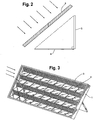
- FIG 2 shows a side view of an example not being part of the present invention.
- a solar cell (3) is rotated at around a 45 degree angle to a module cover (5).
- a reflector (4), also at around a 45 degree angle to the module cover (5) is located approximately perpendicular to and adjacent to the solar cell (3).
- the reflector (4) can be equivalent in length and width to the solar cell (3).
- the reflector (4) and the solar cell (3) form a V-shape with the opening parallel to the module cover (5). Light that enters the module perpendicular to the module cover (5) will hit the solar cell (3) (at a 45 degree angle) directly, or after reflecting off the reflector (4).
- the solar cell (3) combined with the reflector (4) in this orientation collects the same amount of energy as a cell 30% larger oriented parallel to a module cover as shown in prior art Figure 1 .
- Figure 3 shows a parametric view of a solar module with a frame (1) holding an array completely populated with a solar cell (3) and reflector (4) pairings, all at a 45 degree angle to module cover.
- each reflector (4) is shown individually (for clarity), a single extended reflector can be used extending from one end of the module to the other in place of the nine reflectors per row shown in Figure 3 .
- FIG 4 shows a side view of an embodiment of the present invention.
- a solar cell (6) can generally be longer than the solar cells shown in Figure 3 .
- This solar cell (6) is also rotated at around a 45 degree angle with respect to the module cover (5).
- a first reflector (7) is rotated at around a 60 degree angle with respect to the module cover (5), and a second reflector (8) makes around a 30 degree angle with the module cover (5).
- the upper edge of the first reflector (7) is approximately adjacent to the lower edge of the second reflector (8).
- the lower edge of the first reflector (7) is adjacent to the lower edge of the solar cell (6) forming around a 105 degree angle between the first reflector (7) and the solar cell (6).
- Figure 5 shows a perspective view of an array made from the cell-reflector arrangement of Figure 4 .
- the frame (1) holds the solar cells (6) and the two reflector parts (7, 8).
- the alternative embodiment of Figures 4-5 offers an alternative geometry that reflects light on to the solar cell (6) that might not otherwise hit it.
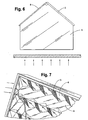
- Figures 6-7 show an alternate embodiment of the present invention where the cells (3) and the reflectors (4) are arranged as in Figure 2 , but rotated by 90 degrees, and including an additional end reflector (9).
- This arrangement allows better light collection (higher concentration of light) from a particular set of daily sun angles (the morning-noon solar arc, or the mid-morning to mid-afternoon solar arc, or the noon-afternoon solar arc) for different orientations of the frame (1).
- Figure 6 is a view looking straight down on the additional reflector (9)
- Figure 7 is a perspective view.
- This embodiment has the advantage of capturing more light from the daily sun angles. Specifically, this embodiment can capture twice as much sunlight per area of solar receiver as the prior art, but only during about half of the day.
- a solar panel constructed according to this embodiment might practically be located on the east or west facing portions of buildings in locations where prior art panels are impractical due to diurnal shading.
- the reflective surfaces can optionally be designed to not reflect infrared (heating) wavelengths of sunlight onto solar cell if desired. This is especially useful if the cell is a photovoltaic cell that produces less electricity as the cell temperature rises. In this manner, only useful wavelengths are normally directed to the cell from the reflectors.
- the present invention is particularly useful for providing solar power in the form of electricity or hot fluid for consumer or commercial use.
- the increased efficiency of the embodiments of the present invention make it superior to prior art products.
Landscapes
- Engineering & Computer Science (AREA)
- Chemical & Material Sciences (AREA)
- Mechanical Engineering (AREA)
- Sustainable Development (AREA)
- Sustainable Energy (AREA)
- Thermal Sciences (AREA)
- Physics & Mathematics (AREA)
- Combustion & Propulsion (AREA)
- Life Sciences & Earth Sciences (AREA)
- General Engineering & Computer Science (AREA)
- Architecture (AREA)
- Civil Engineering (AREA)
- Structural Engineering (AREA)
- Photovoltaic Devices (AREA)
- Information Retrieval, Db Structures And Fs Structures Therefor (AREA)
Claims (11)
- Capteur solaire du type utilisé pour convertir la lumière du soleil en électricité ou pour chauffer un fluide, comprenant une enceinte (1) avec quatre côtés et une couverture transparente (5) permettant de protéger des éléments les surfaces intérieures, caractérisé en ce que le capteur solaire comprend :a) au moins une surface de captage solaire rectangulaire (6) montée à un angle de 45 degrés par rapport à la couverture transparente (5) ;b) une paire de surfaces réfléchissantes (8, 7) à proximité de la surface de captage solaire (6) comprenant une première surface réfléchissante (7) de ladite paire de surfaces réfléchissantes montée selon un angle compris entre 46 et 60 degrés par rapport à la couverture transparente et une seconde surface réfléchissante (8) de ladite paire de surfaces réfléchissantes montée selon un angle par rapport à la couverture transparente qui est complémentaire à l'angle de la première surface réfléchissante par rapport à la couverture transparente, ladite seconde surface réfléchissante comprenant deux bords, l'un adjacent à la première surface réfléchissante (7) et l'autre adjacent à la surface de captage solaire (6), selon lesquels ladite seconde surface réfléchissante s'étend entre la première surface réfléchissante et la surface de captage solaire.
- Capteur solaire selon la revendication 1, caractérisé en ce que la surface de captage solaire (6) comprend une cellule photovoltaïque destinée à convertir la lumière en électricité.
- Capteur solaire selon la revendication 2, caractérisé en ce qu'au moins l'une des surfaces réfléchissantes (7, 8) possèdent un revêtement qui réfléchit une bande de longueurs d'onde de lumière que les cellules photovoltaïques convertissent en électricité, tout en ne réfléchissant pas les longueurs d'ondes infrarouges qui chauffent lesdites cellules photovoltaïques.
- Capteur solaire selon l'une quelconque des revendications précédentes, caractérisé en ce qu'il comprend une pluralité de surfaces de captage solaire (6) et de surfaces réfléchissantes (7, 8).
- Système de captage de lumière comprenant un cadre (1), au moins une cellule solaire (3) fixée au cadre (1) et un premier réflecteur (9) fixé au cadre (1) caractérisé en ce qu'au moins un second réflecteur (4) est fixé au cadre (1) et disposé perpendiculairement au premier réflecteur (9) et ladite au moins une cellule solaire (3) étant disposée perpendiculairement au premier réflecteur (9) et au second réflecteur (4).
- Système de captage de lumière selon la revendication 5, caractérisé en ce qu'il comprend une pluralité de seconds réflecteurs (4),chacun perpendiculaire au premier réflecteur (9).
- Système de captage de lumière selon la revendication 6, caractérisé en ce qu'il comprend une pluralité de cellules solaires (3), chacune perpendiculaire au premier réflecteur (9) et aux seconds réflecteurs (4).
- Système de captage de lumière selon la revendication 7, caractérisé en ce que chacune des cellules solaires (3) est adjacente à l'un des seconds réflecteurs (4).
- Système de captage de lumière selon l'une quelconque des revendications 5 à 8, caractérisé en ce que les premiers (9) et seconds (4) réflecteurs sont en aluminium.
- Système de captage de lumière selon l'une quelconque des revendications 5 à 9, caractérisé en ce que la cellule solaire (3) est une cellule photovoltaïque.
- Système de captage de lumière selon la revendication 10, caractérisé en ce qu'au moins l'un des premiers (9) ou seconds (4) réflecteurs possède un revêtement qui reflète une bande de longueurs d'onde de lumière que la cellule photovoltaïque (3) convertit en électricité tout en ne réfléchissant pas les longueurs d'ondes infrarouges qui chauffent ladite cellule photovoltaïque (3).
Applications Claiming Priority (2)
| Application Number | Priority Date | Filing Date | Title |
|---|---|---|---|
| US11/497,765 US20080047003A1 (en) | 2006-08-02 | 2006-08-02 | Audit system |
| PCT/US2007/015190 WO2008016453A2 (fr) | 2006-08-02 | 2007-06-29 | Procédé et appareil pour disposer une cellule solaire et un réflecteur |
Publications (3)
| Publication Number | Publication Date |
|---|---|
| EP2047518A2 EP2047518A2 (fr) | 2009-04-15 |
| EP2047518A4 EP2047518A4 (fr) | 2015-11-04 |
| EP2047518B1 true EP2047518B1 (fr) | 2018-08-01 |
Family
ID=38997625
Family Applications (1)
| Application Number | Title | Priority Date | Filing Date |
|---|---|---|---|
| EP07796597.8A Active EP2047518B1 (fr) | 2006-08-02 | 2007-06-29 | Disposition d'une cellule solaire et des réflecteurs |
Country Status (9)
| Country | Link |
|---|---|
| US (1) | US20080047003A1 (fr) |
| EP (1) | EP2047518B1 (fr) |
| JP (2) | JP2009545877A (fr) |
| CN (2) | CN101496181B (fr) |
| AU (1) | AU2007279354B2 (fr) |
| BR (1) | BRPI0714645B1 (fr) |
| ES (1) | ES2693278T3 (fr) |
| MX (1) | MX2009001093A (fr) |
| WO (1) | WO2008016453A2 (fr) |
Families Citing this family (12)
| Publication number | Priority date | Publication date | Assignee | Title |
|---|---|---|---|---|
| US8212139B2 (en) | 2008-01-18 | 2012-07-03 | Tenksolar, Inc. | Thin-film photovoltaic module |
| US8933320B2 (en) | 2008-01-18 | 2015-01-13 | Tenksolar, Inc. | Redundant electrical architecture for photovoltaic modules |
| CN102405531B (zh) * | 2009-02-23 | 2016-03-02 | 腾克太阳能公司 | 高效可再生能源系统 |
| EP2443666A4 (fr) | 2009-06-15 | 2013-06-05 | Tenksolar Inc | Panneau solaire indépendant de l'éclairage |
| JP2011082273A (ja) * | 2009-10-05 | 2011-04-21 | Sumiden Communication Engineering Co Ltd | 太陽光発電装置 |
| IT1396128B1 (it) * | 2009-10-07 | 2012-11-16 | Bernardi | Impianto a pannelli fotovoltaici di rendimento elevato. |
| DE102009051766B3 (de) | 2009-10-30 | 2011-04-07 | Solon Se | Photovoltaikanlage mit Reflektorelementen |
| US9773933B2 (en) | 2010-02-23 | 2017-09-26 | Tenksolar, Inc. | Space and energy efficient photovoltaic array |
| US9299861B2 (en) | 2010-06-15 | 2016-03-29 | Tenksolar, Inc. | Cell-to-grid redundandt photovoltaic system |
| KR20140106649A (ko) * | 2011-12-07 | 2014-09-03 | 누보선, 인크. | 낮은 바람 저항 자가 밸러스팅 광발전 모듈 장착 시스템 |
| KR101571926B1 (ko) | 2013-06-25 | 2015-12-07 | 김미애 | 평면거울들을 이용하여 균일하게 집광된 광빔 및 직접 접촉에 의한 냉각법을 이용한 태양광발전 장치 및 방법 |
| CN117271644A (zh) * | 2023-10-11 | 2023-12-22 | 中国工商银行股份有限公司 | 数据库审计方法、装置、设备、介质和程序产品 |
Family Cites Families (23)
| Publication number | Priority date | Publication date | Assignee | Title |
|---|---|---|---|---|
| US3419434A (en) * | 1964-07-21 | 1968-12-31 | Martin Marietta Corp | Solar cell assemblies |
| US4398530A (en) * | 1975-07-09 | 1983-08-16 | Saunders Norman B | Solar collector and heating and cooling system |
| US4020827A (en) * | 1975-08-20 | 1977-05-03 | Paul D. Harrigan | Solar energy collecting system |
| JPS5423488A (en) * | 1977-07-25 | 1979-02-22 | Japan Solar Energy | Optical generator |
| NL7811627A (nl) * | 1978-11-27 | 1980-01-31 | Tno | Zonnecollector. |
| US4296736A (en) * | 1979-12-03 | 1981-10-27 | Olaf Soot | Folded plate solar energy collector |
| JPS60178671A (ja) * | 1984-02-24 | 1985-09-12 | Agency Of Ind Science & Technol | 太陽光発電システム |
| US4867134A (en) * | 1987-10-02 | 1989-09-19 | Brien Philip T O | Fluid-heating solar collector |
| US5361359A (en) * | 1992-08-31 | 1994-11-01 | Trusted Information Systems, Inc. | System and method for controlling the use of a computer |
| US5511537A (en) * | 1994-05-12 | 1996-04-30 | Martin Marietta Energy Systems, Inc. | Smart, passive sun facing surfaces |
| US6079000A (en) * | 1997-12-30 | 2000-06-20 | Unisys Corporation | XPC backup for in-process audit |
| US6286098B1 (en) * | 1998-08-28 | 2001-09-04 | Sap Aktiengesellschaft | System and method for encrypting audit information in network applications |
| JP2000216423A (ja) * | 1999-01-26 | 2000-08-04 | Goro Hashimoto | 反射鏡付き集光型太陽電池装置及び該装置による光発電方法 |
| US6091017A (en) * | 1999-08-23 | 2000-07-18 | Composite Optics Incorporated | Solar concentrator array |
| JP3090923B1 (ja) * | 1999-11-12 | 2000-09-25 | 株式会社エヌ・ティ・ティ ファシリティーズ | 反射式太陽光発電装置 |
| JP2001210854A (ja) * | 2000-01-27 | 2001-08-03 | Sanyo Electric Co Ltd | 太陽電池モジュール |
| JP3558968B2 (ja) * | 2000-06-30 | 2004-08-25 | 株式会社エヌ・ティ・ティ ファシリティーズ | 太陽光発電装置 |
| JP2003329311A (ja) * | 2002-05-14 | 2003-11-19 | Takeo Saito | 集光・集熱装置 |
| US6688053B2 (en) * | 2002-06-27 | 2004-02-10 | Tyson Winarski | Double-pane window that generates solar-powered electricity |
| US7496628B2 (en) * | 2003-02-25 | 2009-02-24 | Susquehanna International Group, Llp | Electronic message filter |
| JP2006046001A (ja) * | 2004-08-06 | 2006-02-16 | Matsushita Electric Works Ltd | 屋根用太陽電池集光装置及び家屋 |
| CN2758977Y (zh) * | 2004-12-17 | 2006-02-15 | 华侨大学 | 板状太阳能发电模块 |
| DE102005038327A1 (de) * | 2005-05-18 | 2006-11-23 | Goldbeck Solar Gmbh | Verblendung für eine Fläche, insbesondere für eine Gebäudefläche |
-
2006
- 2006-08-02 US US11/497,765 patent/US20080047003A1/en not_active Abandoned
-
2007
- 2007-06-29 BR BRPI0714645-0A patent/BRPI0714645B1/pt active IP Right Grant
- 2007-06-29 AU AU2007279354A patent/AU2007279354B2/en not_active Ceased
- 2007-06-29 CN CN2007800284853A patent/CN101496181B/zh active Active
- 2007-06-29 WO PCT/US2007/015190 patent/WO2008016453A2/fr not_active Ceased
- 2007-06-29 CN CN201210151349.6A patent/CN102683464B/zh active Active
- 2007-06-29 EP EP07796597.8A patent/EP2047518B1/fr active Active
- 2007-06-29 ES ES07796597.8T patent/ES2693278T3/es active Active
- 2007-06-29 MX MX2009001093A patent/MX2009001093A/es active IP Right Grant
- 2007-06-29 JP JP2009522760A patent/JP2009545877A/ja active Pending
-
2012
- 2012-11-05 JP JP2012243643A patent/JP5382189B2/ja active Active
Also Published As
| Publication number | Publication date |
|---|---|
| US20080047003A1 (en) | 2008-02-21 |
| AU2007279354B2 (en) | 2013-06-13 |
| JP2013070069A (ja) | 2013-04-18 |
| AU2007279354A1 (en) | 2008-02-07 |
| WO2008016453A3 (fr) | 2008-11-13 |
| EP2047518A4 (fr) | 2015-11-04 |
| JP5382189B2 (ja) | 2014-01-08 |
| BRPI0714645A2 (pt) | 2013-05-14 |
| MX2009001093A (es) | 2009-02-10 |
| BRPI0714645B1 (pt) | 2018-07-10 |
| CN102683464A (zh) | 2012-09-19 |
| CN101496181B (zh) | 2012-07-11 |
| WO2008016453A2 (fr) | 2008-02-07 |
| EP2047518A2 (fr) | 2009-04-15 |
| CN101496181A (zh) | 2009-07-29 |
| CN102683464B (zh) | 2016-01-13 |
| AU2007279354A2 (en) | 2009-02-26 |
| ES2693278T3 (es) | 2018-12-10 |
| JP2009545877A (ja) | 2009-12-24 |
Similar Documents
| Publication | Publication Date | Title |
|---|---|---|
| US8281782B2 (en) | Method and apparatus for arranging a solar cell and reflector | |
| AU2007279354B2 (en) | Method and apparatus for arranging a solar cell and reflector | |
| US20200208880A1 (en) | Concentrating solar power with glasshouses | |
| EP1928028A1 (fr) | Système de tuiles de toit photovoltaïques à concentrateur fluorescent | |
| US20100313933A1 (en) | Reflector-solar receiver assembly and solar module | |
| CN102177591A (zh) | 用于聚光太阳能板的交错开的光收集器 | |
| US20210203274A1 (en) | Photovoltaic cell module | |
| KR101762795B1 (ko) | 양면태양전지셀을 이용한 양면유리 태양전지 모듈과 입체형 반사체를 접목한 고효율 태양전지 시스템 | |
| US20090194146A1 (en) | Method and apparatus for arranging multiple flat reflector facets around a solar cell or solar panel | |
| US20110240122A1 (en) | Compact solar apparatus for producing electricity and method of producing electricity using a compact solar apparatus | |
| US20140102510A1 (en) | Concentrating solar energy collector | |
| CN110798141B (zh) | 一种光伏发电装置 | |
| US20130276865A1 (en) | Saw-tooth shaped solar module | |
| RU2557272C1 (ru) | Кровельная солнечная панель | |
| WO2013095120A1 (fr) | Système concentrateur solaire | |
| KR101029543B1 (ko) | 태양열 집열판 또는 태양전지모듈의 프레임용 반사부재 | |
| CN113345974A (zh) | 一种农光互补光伏发电装置 | |
| US20110214710A1 (en) | Solar collection device with non-moving concentration elements | |
| KR102691150B1 (ko) | 태양광 집광모듈 | |
| US20250317101A1 (en) | Tracking-type solar trough assembly | |
| US20120012148A1 (en) | High surface area photovoltaic systems | |
| KR20240142792A (ko) | 양면형 태양전지 패널용 집광모듈 및 이를 구비하여 이루어지는 어레이 구조 | |
| WO2006039149A2 (fr) | Appareil solaire compact servant a produire de l'electricite | |
| WO2016132384A1 (fr) | Réseau de micro-concentrateurs modulaire basé sur un système de suivi solaire multidirectionnel pour la récupération d'énergie photovoltaïque et thermique |
Legal Events
| Date | Code | Title | Description |
|---|---|---|---|
| PUAI | Public reference made under article 153(3) epc to a published international application that has entered the european phase |
Free format text: ORIGINAL CODE: 0009012 |
|
| 17P | Request for examination filed |
Effective date: 20090123 |
|
| AK | Designated contracting states |
Kind code of ref document: A2 Designated state(s): AT BE BG CH CY CZ DE DK EE ES FI FR GB GR HU IE IS IT LI LT LU LV MC MT NL PL PT RO SE SI SK TR |
|
| AX | Request for extension of the european patent |
Extension state: AL BA HR MK RS |
|
| DAX | Request for extension of the european patent (deleted) | ||
| A4 | Supplementary search report drawn up and despatched |
Effective date: 20151006 |
|
| RIC1 | Information provided on ipc code assigned before grant |
Ipc: H01L 31/052 20140101AFI20150930BHEP Ipc: F24J 2/10 20060101ALI20150930BHEP Ipc: F24J 2/08 20060101ALI20150930BHEP |
|
| STAA | Information on the status of an ep patent application or granted ep patent |
Free format text: STATUS: EXAMINATION IS IN PROGRESS |
|
| 17Q | First examination report despatched |
Effective date: 20161025 |
|
| GRAP | Despatch of communication of intention to grant a patent |
Free format text: ORIGINAL CODE: EPIDOSNIGR1 |
|
| STAA | Information on the status of an ep patent application or granted ep patent |
Free format text: STATUS: GRANT OF PATENT IS INTENDED |
|
| RIC1 | Information provided on ipc code assigned before grant |
Ipc: F24S 23/77 20180101ALI20180226BHEP Ipc: H02S 40/22 20140101ALI20180226BHEP Ipc: H02S 20/23 20140101ALI20180226BHEP Ipc: H01L 31/042 20060101AFI20180226BHEP |
|
| INTG | Intention to grant announced |
Effective date: 20180314 |
|
| RAP1 | Party data changed (applicant data changed or rights of an application transferred) |
Owner name: SIMON, DANIEL |
|
| RIN1 | Information on inventor provided before grant (corrected) |
Inventor name: SIMON, DANIEL |
|
| GRAS | Grant fee paid |
Free format text: ORIGINAL CODE: EPIDOSNIGR3 |
|
| GRAA | (expected) grant |
Free format text: ORIGINAL CODE: 0009210 |
|
| STAA | Information on the status of an ep patent application or granted ep patent |
Free format text: STATUS: THE PATENT HAS BEEN GRANTED |
|
| AK | Designated contracting states |
Kind code of ref document: B1 Designated state(s): AT BE BG CH CY CZ DE DK EE ES FI FR GB GR HU IE IS IT LI LT LU LV MC MT NL PL PT RO SE SI SK TR |
|
| REG | Reference to a national code |
Ref country code: GB Ref legal event code: FG4D |
|
| REG | Reference to a national code |
Ref country code: CH Ref legal event code: EP Ref country code: AT Ref legal event code: REF Ref document number: 1025339 Country of ref document: AT Kind code of ref document: T Effective date: 20180815 |
|
| REG | Reference to a national code |
Ref country code: IE Ref legal event code: FG4D |
|
| REG | Reference to a national code |
Ref country code: DE Ref legal event code: R096 Ref document number: 602007055582 Country of ref document: DE |
|
| REG | Reference to a national code |
Ref country code: NL Ref legal event code: FP |
|
| REG | Reference to a national code |
Ref country code: ES Ref legal event code: FG2A Ref document number: 2693278 Country of ref document: ES Kind code of ref document: T3 Effective date: 20181210 |
|
| REG | Reference to a national code |
Ref country code: LT Ref legal event code: MG4D |
|
| REG | Reference to a national code |
Ref country code: AT Ref legal event code: MK05 Ref document number: 1025339 Country of ref document: AT Kind code of ref document: T Effective date: 20180801 |
|
| PG25 | Lapsed in a contracting state [announced via postgrant information from national office to epo] |
Ref country code: LT Free format text: LAPSE BECAUSE OF FAILURE TO SUBMIT A TRANSLATION OF THE DESCRIPTION OR TO PAY THE FEE WITHIN THE PRESCRIBED TIME-LIMIT Effective date: 20180801 Ref country code: PL Free format text: LAPSE BECAUSE OF FAILURE TO SUBMIT A TRANSLATION OF THE DESCRIPTION OR TO PAY THE FEE WITHIN THE PRESCRIBED TIME-LIMIT Effective date: 20180801 Ref country code: BG Free format text: LAPSE BECAUSE OF FAILURE TO SUBMIT A TRANSLATION OF THE DESCRIPTION OR TO PAY THE FEE WITHIN THE PRESCRIBED TIME-LIMIT Effective date: 20181101 Ref country code: SE Free format text: LAPSE BECAUSE OF FAILURE TO SUBMIT A TRANSLATION OF THE DESCRIPTION OR TO PAY THE FEE WITHIN THE PRESCRIBED TIME-LIMIT Effective date: 20180801 Ref country code: GR Free format text: LAPSE BECAUSE OF FAILURE TO SUBMIT A TRANSLATION OF THE DESCRIPTION OR TO PAY THE FEE WITHIN THE PRESCRIBED TIME-LIMIT Effective date: 20181102 Ref country code: FI Free format text: LAPSE BECAUSE OF FAILURE TO SUBMIT A TRANSLATION OF THE DESCRIPTION OR TO PAY THE FEE WITHIN THE PRESCRIBED TIME-LIMIT Effective date: 20180801 Ref country code: AT Free format text: LAPSE BECAUSE OF FAILURE TO SUBMIT A TRANSLATION OF THE DESCRIPTION OR TO PAY THE FEE WITHIN THE PRESCRIBED TIME-LIMIT Effective date: 20180801 Ref country code: IS Free format text: LAPSE BECAUSE OF FAILURE TO SUBMIT A TRANSLATION OF THE DESCRIPTION OR TO PAY THE FEE WITHIN THE PRESCRIBED TIME-LIMIT Effective date: 20181201 |
|
| PG25 | Lapsed in a contracting state [announced via postgrant information from national office to epo] |
Ref country code: LV Free format text: LAPSE BECAUSE OF FAILURE TO SUBMIT A TRANSLATION OF THE DESCRIPTION OR TO PAY THE FEE WITHIN THE PRESCRIBED TIME-LIMIT Effective date: 20180801 |
|
| PG25 | Lapsed in a contracting state [announced via postgrant information from national office to epo] |
Ref country code: RO Free format text: LAPSE BECAUSE OF FAILURE TO SUBMIT A TRANSLATION OF THE DESCRIPTION OR TO PAY THE FEE WITHIN THE PRESCRIBED TIME-LIMIT Effective date: 20180801 Ref country code: CZ Free format text: LAPSE BECAUSE OF FAILURE TO SUBMIT A TRANSLATION OF THE DESCRIPTION OR TO PAY THE FEE WITHIN THE PRESCRIBED TIME-LIMIT Effective date: 20180801 Ref country code: EE Free format text: LAPSE BECAUSE OF FAILURE TO SUBMIT A TRANSLATION OF THE DESCRIPTION OR TO PAY THE FEE WITHIN THE PRESCRIBED TIME-LIMIT Effective date: 20180801 |
|
| REG | Reference to a national code |
Ref country code: DE Ref legal event code: R097 Ref document number: 602007055582 Country of ref document: DE |
|
| PG25 | Lapsed in a contracting state [announced via postgrant information from national office to epo] |
Ref country code: DK Free format text: LAPSE BECAUSE OF FAILURE TO SUBMIT A TRANSLATION OF THE DESCRIPTION OR TO PAY THE FEE WITHIN THE PRESCRIBED TIME-LIMIT Effective date: 20180801 Ref country code: SK Free format text: LAPSE BECAUSE OF FAILURE TO SUBMIT A TRANSLATION OF THE DESCRIPTION OR TO PAY THE FEE WITHIN THE PRESCRIBED TIME-LIMIT Effective date: 20180801 |
|
| PLBE | No opposition filed within time limit |
Free format text: ORIGINAL CODE: 0009261 |
|
| STAA | Information on the status of an ep patent application or granted ep patent |
Free format text: STATUS: NO OPPOSITION FILED WITHIN TIME LIMIT |
|
| 26N | No opposition filed |
Effective date: 20190503 |
|
| PG25 | Lapsed in a contracting state [announced via postgrant information from national office to epo] |
Ref country code: SI Free format text: LAPSE BECAUSE OF FAILURE TO SUBMIT A TRANSLATION OF THE DESCRIPTION OR TO PAY THE FEE WITHIN THE PRESCRIBED TIME-LIMIT Effective date: 20180801 |
|
| PG25 | Lapsed in a contracting state [announced via postgrant information from national office to epo] |
Ref country code: MC Free format text: LAPSE BECAUSE OF FAILURE TO SUBMIT A TRANSLATION OF THE DESCRIPTION OR TO PAY THE FEE WITHIN THE PRESCRIBED TIME-LIMIT Effective date: 20180801 |
|
| REG | Reference to a national code |
Ref country code: CH Ref legal event code: PL |
|
| GBPC | Gb: european patent ceased through non-payment of renewal fee |
Effective date: 20190629 |
|
| REG | Reference to a national code |
Ref country code: BE Ref legal event code: MM Effective date: 20190630 |
|
| PG25 | Lapsed in a contracting state [announced via postgrant information from national office to epo] |
Ref country code: TR Free format text: LAPSE BECAUSE OF FAILURE TO SUBMIT A TRANSLATION OF THE DESCRIPTION OR TO PAY THE FEE WITHIN THE PRESCRIBED TIME-LIMIT Effective date: 20180801 |
|
| PG25 | Lapsed in a contracting state [announced via postgrant information from national office to epo] |
Ref country code: GB Free format text: LAPSE BECAUSE OF NON-PAYMENT OF DUE FEES Effective date: 20190629 |
|
| PG25 | Lapsed in a contracting state [announced via postgrant information from national office to epo] |
Ref country code: LI Free format text: LAPSE BECAUSE OF NON-PAYMENT OF DUE FEES Effective date: 20190630 Ref country code: CH Free format text: LAPSE BECAUSE OF NON-PAYMENT OF DUE FEES Effective date: 20190630 Ref country code: BE Free format text: LAPSE BECAUSE OF NON-PAYMENT OF DUE FEES Effective date: 20190630 Ref country code: LU Free format text: LAPSE BECAUSE OF NON-PAYMENT OF DUE FEES Effective date: 20190629 |
|
| PG25 | Lapsed in a contracting state [announced via postgrant information from national office to epo] |
Ref country code: PT Free format text: LAPSE BECAUSE OF FAILURE TO SUBMIT A TRANSLATION OF THE DESCRIPTION OR TO PAY THE FEE WITHIN THE PRESCRIBED TIME-LIMIT Effective date: 20181201 |
|
| PG25 | Lapsed in a contracting state [announced via postgrant information from national office to epo] |
Ref country code: CY Free format text: LAPSE BECAUSE OF FAILURE TO SUBMIT A TRANSLATION OF THE DESCRIPTION OR TO PAY THE FEE WITHIN THE PRESCRIBED TIME-LIMIT Effective date: 20180801 |
|
| PG25 | Lapsed in a contracting state [announced via postgrant information from national office to epo] |
Ref country code: HU Free format text: LAPSE BECAUSE OF FAILURE TO SUBMIT A TRANSLATION OF THE DESCRIPTION OR TO PAY THE FEE WITHIN THE PRESCRIBED TIME-LIMIT; INVALID AB INITIO Effective date: 20070629 Ref country code: MT Free format text: LAPSE BECAUSE OF FAILURE TO SUBMIT A TRANSLATION OF THE DESCRIPTION OR TO PAY THE FEE WITHIN THE PRESCRIBED TIME-LIMIT Effective date: 20180801 |
|
| P01 | Opt-out of the competence of the unified patent court (upc) registered |
Effective date: 20230524 |
|
| PGFP | Annual fee paid to national office [announced via postgrant information from national office to epo] |
Ref country code: NL Payment date: 20230327 Year of fee payment: 17 |
|
| PGFP | Annual fee paid to national office [announced via postgrant information from national office to epo] |
Ref country code: IE Payment date: 20240425 Year of fee payment: 18 |
|
| PGFP | Annual fee paid to national office [announced via postgrant information from national office to epo] |
Ref country code: DE Payment date: 20240613 Year of fee payment: 18 |
|
| PGFP | Annual fee paid to national office [announced via postgrant information from national office to epo] |
Ref country code: FR Payment date: 20240624 Year of fee payment: 18 |
|
| PGFP | Annual fee paid to national office [announced via postgrant information from national office to epo] |
Ref country code: IT Payment date: 20240607 Year of fee payment: 18 |
|
| PGFP | Annual fee paid to national office [announced via postgrant information from national office to epo] |
Ref country code: ES Payment date: 20240705 Year of fee payment: 18 |
|
| REG | Reference to a national code |
Ref country code: DE Ref legal event code: R079 Ref document number: 602007055582 Country of ref document: DE Free format text: PREVIOUS MAIN CLASS: H01L0031042000 Ipc: H10F0019000000 |
|
| REG | Reference to a national code |
Ref country code: NL Ref legal event code: MM Effective date: 20240701 |
|
| PG25 | Lapsed in a contracting state [announced via postgrant information from national office to epo] |
Ref country code: NL Free format text: LAPSE BECAUSE OF NON-PAYMENT OF DUE FEES Effective date: 20240701 |
|
| PG25 | Lapsed in a contracting state [announced via postgrant information from national office to epo] |
Ref country code: NL Free format text: LAPSE BECAUSE OF NON-PAYMENT OF DUE FEES Effective date: 20240701 |
|
| REG | Reference to a national code |
Ref country code: DE Ref legal event code: R119 Ref document number: 602007055582 Country of ref document: DE |
|
| PG25 | Lapsed in a contracting state [announced via postgrant information from national office to epo] |
Ref country code: DE Free format text: LAPSE BECAUSE OF NON-PAYMENT OF DUE FEES Effective date: 20260101 Ref country code: IE Free format text: LAPSE BECAUSE OF NON-PAYMENT OF DUE FEES Effective date: 20250629 |
|
| PG25 | Lapsed in a contracting state [announced via postgrant information from national office to epo] |
Ref country code: IT Free format text: LAPSE BECAUSE OF NON-PAYMENT OF DUE FEES Effective date: 20250629 |
|
| PG25 | Lapsed in a contracting state [announced via postgrant information from national office to epo] |
Ref country code: FR Free format text: LAPSE BECAUSE OF NON-PAYMENT OF DUE FEES Effective date: 20250630 |