EP2047765A2 - Anwendung von Zipplängen auf das Netz - Google Patents
Anwendung von Zipplängen auf das Netz Download PDFInfo
- Publication number
- EP2047765A2 EP2047765A2 EP08172855A EP08172855A EP2047765A2 EP 2047765 A2 EP2047765 A2 EP 2047765A2 EP 08172855 A EP08172855 A EP 08172855A EP 08172855 A EP08172855 A EP 08172855A EP 2047765 A2 EP2047765 A2 EP 2047765A2
- Authority
- EP
- European Patent Office
- Prior art keywords
- zipper
- web
- lengths
- turret
- film
- Prior art date
- Legal status (The legal status is an assumption and is not a legal conclusion. Google has not performed a legal analysis and makes no representation as to the accuracy of the status listed.)
- Withdrawn
Links
Images
Classifications
-
- A—HUMAN NECESSITIES
- A44—HABERDASHERY; JEWELLERY
- A44B—BUTTONS, PINS, BUCKLES, SLIDE FASTENERS, OR THE LIKE
- A44B19/00—Slide fasteners
- A44B19/42—Making by processes not fully provided for in one other class, e.g. B21D53/50, B21F45/18, B22D17/16, B29D5/00
-
- B—PERFORMING OPERATIONS; TRANSPORTING
- B31—MAKING ARTICLES OF PAPER, CARDBOARD OR MATERIAL WORKED IN A MANNER ANALOGOUS TO PAPER; WORKING PAPER, CARDBOARD OR MATERIAL WORKED IN A MANNER ANALOGOUS TO PAPER
- B31B—MAKING CONTAINERS OF PAPER, CARDBOARD OR MATERIAL WORKED IN A MANNER ANALOGOUS TO PAPER
- B31B70/00—Making flexible containers, e.g. envelopes or bags
- B31B70/74—Auxiliary operations
- B31B70/81—Forming or attaching accessories, e.g. opening devices, closures or tear strings
- B31B70/813—Applying closures
- B31B70/8131—Making bags having interengaging closure elements
- B31B70/8133—Applying the closure elements in the cross direction
Definitions
- the present invention relates to reclosable fasteners of the type known as "zippers". These consist of first and second lengths of material, usually plastics, which are shaped to engage with each other along their lengths.
- the individual lengths of material are known as “profiles”.
- the zipper is known as a “slider zipper”.
- the present invention is concerned with the application of lengths of slider zipper to a web of material in a manner known as "cross-web technology”. This means that individual lengths of zipper are applied to the web to extend transversely, usually perpendicularly, to the longitudinal dimension of the web and spaced at longitudinal intervals.
- the present invention provides an apparatus for applying pre-cut lengths of zipper transversely to a moving web of material at intervals spaced in the direction of movement of the web, comprising:
- the means for mounting the sliders on the zipper comprise a rotary zipper applicator.
- a knife is located between the slider applicator and the feeding location for cutting a continuous supply of zipper into the pre-cut lengths.
- each groove in the turret includes a wider portion for receiving the slider on each pre-cut zipper length, each wider portion preferably extending to slightly beyond the mid-point of the groove from an insertion end thereof.
- the means for removal and attachment of the zipper lengths comprises a heated sealing bar which is movable towards and away from the film and is located adjacent the attachment location at the opposite side of the film to the turret.
- the apparatus in which the slider-mounting means produces zipper having its profiles disengaged from each other, the apparatus preferably includes, between the slider-mounting means and the turret, a device for engaging the zipper profiles with each other, the device comprising a pair of rollers through the nip of which the zipper passes and which are arranged to engage the profiles of the zipper with each other and to separate from each other to allow the sliders to pass therebetween.
- the roller surfaces forming the nip are convex.
- the apparatus includes a form-fill-seal machine arranged to receive the web with zippers attached and to form the web into bags and to fill the bags with a product, the zipper lengths forming reclosable fasteners of the bags.
- a form-fill-seal machine arranged to receive the web with zippers attached and to form the web into bags and to fill the bags with a product, the zipper lengths forming reclosable fasteners of the bags.
- the apparatus includes a machine arranged to receive the web with zippers attached and to form the web into bags for subsequent filling with a product, the zipper lengths forming reclosable fasteners of the bags.
- Another option is to include a means for forming the web with zippers attached into a roll for subsequent use in making empty bags or in a form-fill-seal machine.
- the invention provides a device for engaging the profiles of a slider zipper, the device comprising a pair of rollers through the nip of which the zipper passes and which are arranged to engage the profiles of the zipper with each other and to separate from each other to allow the sliders to pass therebetween.
- the roller surfaces forming the nip are convex.
- the invention also provides a method of applying pre-cut lengths of zipper transversely to a moving web of material at intervals spaced in the direction of movement of the web, comprising
- the sliders are mounted on the zipper lengths by means of a rotary zipper applicator.
- the sliders are mounted on a continuous length zipper which is subsequently cut into lengths.
- re-engagement is preferably by passing the zipper between the nip of a pair of rollers which are arranged to separate from each other to allow the sliders to pass therebetween.
- the method includes the further step of feeding the web with zippers attached to a form-fill-seal machine arranged to receive the web with zippers attached and to form the web into bags and to fill the bags with a product the zipper lengths forming reclosable fasteners of the bags.
- the method includes the further step of feeding the web with zippers attached to a machine for forming the web into bags for subsequent filling with a product, the zipper lengths forming reclosable fasteners of the bags.
- Another option is to include the further step of forming the web with zippers attached into a roll for subsequent use in making empty bags or in a form-fill-seal machine.
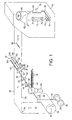
- FIG. 1 of the drawings shows a supply roll 10 of a plastics film material 12, for example polyethylene, which is suitable for use in making plastic bags.
- the roll 10 is mounted for rotation about a horizontal axis 14. From the roll 10 the film passes vertically upwards to a diverting roller 16, by which the advancing film is directed to move in a horizontal direction. The film now passes beneath a rotary turret 18 and then to a vertically-operating form-fill-seal machine which is shown generally by the reference numeral 20.
- the rotary turret 18 is driven to rotate in a counterclockwise direction by drive means (not shown) about a horizontal axis 22 which is parallel to the plane of the film material and spaced vertically therefrom.
- the axis 22 extends perpendicularly to the longitudinal edges 24, 26 of the film 12.
- the rotary turret 18 has a cylindrical surface 28 which has in it four equally-spaced axially extending grooves, of which only three 30a, 30b, 30c are visible in figure 1 .
- the grooves are dimensioned each to receive a pre-cut length of zipper with a slider attached at its mid-point.
- the length of each piece of zipper is just less than one-half of the width of the film material 12.
- Each groove is enlarged in width from its end which is the left-hand end as shown in figure 1 to a point just beyond the mid-point of the groove. This allows each groove 30a, 30b, 30c to receive a pre-cut length of zipper with a centrally-mounted slider by insertion from the left-hand end in figure 1 .
- a supply of zipper 34 with its profiles engaged is stored in a continuous length on a spool 36 which is mounted for rotation about a horizontal axis 38. From the spool 36, the zipper passes vertically upwards to a diverting roller 40, which changes the direction of movement of the zipper into a horizontal direction.
- the horizontally directed zipper now passes through a rotary slider applicator 42, into which a magazine 44 charged with sliders 46 is fed in a horizontal direction substantially perpendicular to the direction of movement of the zipper 34 through the slider applicator 42.
- the slider applicator 42 is of a type which is known per se and is obtainable from Supreme Plastics Limited of Supreme House, 300 Regents Park Road, London N3 2TL, UK.
- the applicator 42 is arranged to mount sliders 46 from the magazine 44 at predetermined intervals along the length of the zipper 34. During this operation, the profiles of the zipper are separated from each other.
- the zipper 34 passes through the nip of a first pair of rollers 48, 50 and are arranged to bring the zipper profiles into engagement with each other except where the sliders 46 are located.
- the rollers 48, 50 are mounted to allow for relative separating movement of the rollers to take place when a slider 46 mounted on the zipper passes through the nip of the rollers.
- the rollers 48, 50 are thus arranged to ride over the sliders 46 as they pass through the nip of the rollers.
- the surfaces of the rollers 48, 50 defining the nip are convex.
- the zipper 34 now passes through the nip of a second pair of rollers 52, 54 which are driven in opposite directions by drive means (not shown) to draw the zipper from the storage spool 32, through the applicator 42 and the first pair of rollers 48, 50 and on towards the rotary turret 18.
- a cutting knife 56 is located between the rollers 52, 54 and the rotary turret 18.
- the knife 56 is positioned to cut the zipper 34 into predetermined lengths 58, such that each length has a slider 46 mounted centrally and is of a length equal to slightly less than one half the width of the film 12 between its longitudinal edges 24, 26.
- a heated sealing bar 60 is located beneath the film 12 and aligned with the grooves 30a, 30b, 30c of the turret when these are located at the "6-o'clock" position.
- the sealing bar 60 is movable in a vertical direction towards and away from the film 12 by control means (not shown).
- the pre-cut lengths 58 of zipper are cut and fed as described above to the turret 18 to be received in a first one 30a of its grooves when that groove is uppermost (ie in the "12-o'clock" position).
- the rotation of the turret is stopped by suitable control of its drive means whilst feeding of the zipper takes place.
- the zipper length 58 with its respective slider 46 mounted thereon is located centrally in the groove 30a.
- the turret is now driven to rotate counterclockwise through 90° (ie until the groove 30a is located at the "9-o'clock” position) and stopped to allow a further zipper length inserted in the groove 30b which is now to be found at the "12-o'clock” position. Further movement of the turret counterclockwise through another 90° brings the groove 30a to the "6-o'clock” position at which the turret 18 is again stopped. The web is also stopped.
- the sealing bar 60 is now arranged to move upwards to contact the film 12 beneath the groove 30a when in the "6-o'clock" position. This action of the sealing bar removes the zipper length 58 is from the groove 30a and causes it to be heat-sealed to the film 12 so that it extends transversely of the film 12 mid-way between and perpendicular to its longitudinal edges 24, 26.
- the slider 46 is thus located centrally of the film 12.
- the form-fill-seal machine 20 operates in a known manner and comprises a forming collar 62, over which the film 12 passes.
- the collar 62 is shaped to form the film into a tubular shape around the outer surface of a filling cylinder 64, into the hollow centre 66 of which product to be filled into bags formed by the machine 20 can be fed.
- the path of the film through the machine 20 is suitably relieved to allow for passage of the sliders 46.
- the longitudinal edges 24, 26 of the film are overlapped so that they can be sealed together by a heated sealing bar 68 which is movable back-and-forth in the directions of the arrows 70 in the figure.
- a drive belt 72 operating over rollers 74, 76 contacts the film 12 as it passes down the outside of the cylinder 64.
- a further pair of rollers and a drive belt are located at the opposite side of the cylinder 64 and, together with the belt 72 and rollers 74, 76, apply a traction with draws the film through the apparatus described above from the supply roll 10.
- Beneath the filling cylinder 64 are positioned in known manner a pair of heated sealing bars 78 which incorporate a cutting knife (not shown).
- the heated bars 78 and the knife are arranged simultaneously to form a transverse top seal on each bag formed after it has been filled, to sever that bag from the next bag and to form a transverse bottom seal on the next bag. Filled bags heat sealed top and bottom are thereby produced.
- a heated zipper-sealing bar 80 is mounted and arranged for movement towards and away from a fixed bar 82.
- the heated bar 80 moves towards the fixed bar to clamp the film and zipper strip 58 therebetween and thus attach the unattached zipper profile to the opposite wall of the bag.
- a reclosable slider zipper seal inside the bag below its top seal is thereby formed.
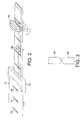
- Figure 2 of the drawings shows a modification of the apparatus shown in figure 1 , in which the vertical form-fill-seal machine 20 is replaced by a horizontal form-fill-seal machine which operates in a known manner in which the film 12 with slider zippers 58 mounted thereon is formed in a forming box 84 around product located on a drive belt (not shown) and then sealed and severed into individual bags by a back sealer 86 and rotary sealing and cutting bars 88.
- a reclosable slider zipper seal is also formed inside the bag by a heated zipper-sealing bar.
- the form-fill-seal machines are replaced by respective bag-making machines to produce empty bags which can be filled and sealed subsequently.
- Such bags are known as "pre-made bags”.
- the form-fill-seal machine 20 is omitted and the film 12 simply re-wound onto a reel for subsequent use either in a vertical or horizontal form-fill-seal machine or in a bag-making machine as mentioned above.
- This process is of the type known as a "reel-to-reel" process.
Landscapes
- Making Paper Articles (AREA)
- Slide Fasteners (AREA)
- Bag Frames (AREA)
- Containers And Plastic Fillers For Packaging (AREA)
Applications Claiming Priority (2)
| Application Number | Priority Date | Filing Date | Title |
|---|---|---|---|
| GBGB0406626.2A GB0406626D0 (en) | 2004-03-24 | 2004-03-24 | Application of zipper lengths to a web |
| EP05729432A EP1737311B1 (de) | 2004-03-24 | 2005-03-22 | Aufbringen von profilverschlusslängen an einer bahn |
Related Parent Applications (1)
| Application Number | Title | Priority Date | Filing Date |
|---|---|---|---|
| EP05729432A Division EP1737311B1 (de) | 2004-03-24 | 2005-03-22 | Aufbringen von profilverschlusslängen an einer bahn |
Publications (2)
| Publication Number | Publication Date |
|---|---|
| EP2047765A2 true EP2047765A2 (de) | 2009-04-15 |
| EP2047765A3 EP2047765A3 (de) | 2013-11-20 |
Family
ID=32188606
Family Applications (2)
| Application Number | Title | Priority Date | Filing Date |
|---|---|---|---|
| EP05729432A Ceased EP1737311B1 (de) | 2004-03-24 | 2005-03-22 | Aufbringen von profilverschlusslängen an einer bahn |
| EP08172855.2A Withdrawn EP2047765A3 (de) | 2004-03-24 | 2005-03-22 | Anwendung von Zipplängen auf das Netz |
Family Applications Before (1)
| Application Number | Title | Priority Date | Filing Date |
|---|---|---|---|
| EP05729432A Ceased EP1737311B1 (de) | 2004-03-24 | 2005-03-22 | Aufbringen von profilverschlusslängen an einer bahn |
Country Status (9)
| Country | Link |
|---|---|
| US (1) | US20070271874A1 (de) |
| EP (2) | EP1737311B1 (de) |
| JP (2) | JP4773425B2 (de) |
| AU (2) | AU2005226944B2 (de) |
| CA (2) | CA2560932C (de) |
| DE (1) | DE602005023139D1 (de) |
| GB (1) | GB0406626D0 (de) |
| PL (1) | PL1737311T3 (de) |
| WO (1) | WO2005092139A1 (de) |
Cited By (1)
| Publication number | Priority date | Publication date | Assignee | Title |
|---|---|---|---|---|
| CN102581252A (zh) * | 2012-02-20 | 2012-07-18 | 义乌市华大压铸有限公司 | 一种全自动拉链头压铸件分料机及分料方法 |
Families Citing this family (10)
| Publication number | Priority date | Publication date | Assignee | Title |
|---|---|---|---|---|
| GB0419218D0 (en) | 2004-08-28 | 2004-09-29 | Supreme Plastics Holdings Ltd | Reclosable bag and zipper therefor |
| US20070230834A1 (en) * | 2006-03-31 | 2007-10-04 | Schneider John H | Packages having reclosable pour spout with slider-operated zipper |
| US7681732B2 (en) | 2008-01-11 | 2010-03-23 | Cryovac, Inc. | Laminated lidstock |
| US20090317151A1 (en) * | 2008-06-24 | 2009-12-24 | Water-Line Sa | Feeding and fixing apparatus for feeding and fixing a functional element to a sheet of film |
| WO2010092404A1 (en) | 2009-02-16 | 2010-08-19 | Illinois Tool Works Inc. | Zipper fasteners, sliders therefor, methods and apparatus for applying zipper fasteners to substrates |
| US9061783B2 (en) * | 2010-04-29 | 2015-06-23 | Illinois Tool Works Inc. | Fin seal registration in manufacture of reclosable packages |
| FR3021034B1 (fr) * | 2014-05-15 | 2017-05-12 | S2F Flexico | Machine de formage-remplissage-scellage pour sachet a ruban |
| CN110652080B (zh) * | 2018-06-29 | 2022-06-14 | Ykk株式会社 | 打开件供给方法及打开件供给装置 |
| WO2023225262A1 (en) | 2022-05-20 | 2023-11-23 | Cmd Corporation | Bag making machines and methods thereof |
| EP4620664A1 (de) | 2024-03-19 | 2025-09-24 | Altopack S.P.A. | Gruppe zum anbringen eines reissverschlussstreifens auf einem langen teigwarenbeutel |
Family Cites Families (24)
| Publication number | Priority date | Publication date | Assignee | Title |
|---|---|---|---|---|
| US1960580A (en) * | 1930-08-20 | 1934-05-29 | Libbey Owens Ford Glass Co | Process and apparatus for producing laminated glass |
| FR2532162B1 (fr) * | 1982-08-31 | 1986-05-09 | Flexico France Sarl | Machine pour la fabrication de sacs en matiere plastique pouvant etre ouverts ou fermes par un curseur, appareil de positionnement de curseurs, equipant une telle machine; son mode de fonctionnement |
| US4655862A (en) * | 1984-01-30 | 1987-04-07 | Minigrip, Incorporated | Method of and means for making reclosable bags and method therefor |
| US4582549A (en) * | 1985-03-15 | 1986-04-15 | Minigrip, Inc. | Method and apparatus for producing bag making material having reclosable fasteners |
| JPH0527046Y2 (de) * | 1986-04-15 | 1993-07-09 | ||
| US4709398A (en) * | 1987-01-07 | 1987-11-24 | Minigrip, Inc. | Chain bags, method and apparatus |
| JP2556863B2 (ja) * | 1987-07-23 | 1996-11-27 | 日立金属株式会社 | Fe基磁性合金膜 |
| JPH0719289Y2 (ja) * | 1987-08-07 | 1995-05-10 | ワイケイケイ株式会社 | スライドフアスナ−用スライダ−の引上げ装置 |
| US5319430A (en) * | 1993-01-04 | 1994-06-07 | Xerox Corporation | Fuser mechanism having crowned rolls |
| US6003582A (en) * | 1997-07-17 | 1999-12-21 | Hudson-Sharp Machine Co. | Apparatus for applying reclosable fasteners to a web of film |
| JP3782566B2 (ja) * | 1997-10-31 | 2006-06-07 | 三甲株式会社 | 合成樹脂製パレットへの滑り止めテープ溶着装置 |
| US6694704B1 (en) * | 1998-04-20 | 2004-02-24 | Illinois Tool Works Inc. | Process and apparatus for forming packaging bags with a fastener |
| DE29808817U1 (de) * | 1998-05-15 | 1999-09-23 | Robert Bosch Gmbh, 70469 Stuttgart | Vorrichtung zum Herstellen von wiederverschließbaren Schlauchbeutelpackungen |
| US6609353B1 (en) * | 1998-06-08 | 2003-08-26 | Illinois Tool Works Inc. | Application system for sliders at form-fill-seal machine |
| US6161271A (en) * | 1999-07-29 | 2000-12-19 | Reynolds Consumer Products, Inc. | Method for mounting a slider mechanism to recloseable flexible packaging |
| US6588176B1 (en) * | 1999-12-17 | 2003-07-08 | Reynolds Consumer Products, Inc. | Methods of manufacturing reclosable packages using transverse closure and slider applicator |
| US6871473B1 (en) * | 2000-08-10 | 2005-03-29 | Pactiv Corporation | Method and apparatus for making reclosable plastic bags using a pre-applied slider-operated fastener |
| JP2002154576A (ja) * | 2000-11-10 | 2002-05-28 | Reynolds Consumer Products Inc | 再封止可能パッケージへのスライダーの配置方法およびそれにより製造した物品 |
| JP2002199910A (ja) * | 2000-12-18 | 2002-07-16 | Reynolds Consumer Products Inc | 横断配置された咬合子およびスライダーの供給具を使用する再封止可能なパッケージの製造方法 |
| JP2002316367A (ja) * | 2001-02-16 | 2002-10-29 | Seibu Kikai Kk | ジッパストリップ取り付け装置及びジッパ付き袋の製袋方法 |
| JP2004017393A (ja) * | 2002-06-14 | 2004-01-22 | Showa Highpolymer Co Ltd | プラスチックチャックの開閉装置及びプラスチックチャック付き袋体の製造方法 |
| US20040007309A1 (en) * | 2002-07-11 | 2004-01-15 | Kevin Owen | Tack knife |
| US6810642B2 (en) * | 2002-08-05 | 2004-11-02 | Illinois Tool Works Inc. | Method and apparatus for sealing zippers to bag making film |
| US7530938B2 (en) * | 2003-07-01 | 2009-05-12 | Illinois Tool Works Inc. | Pneumatic roller for passing film with attachments through rollers of machine |
-
2004
- 2004-03-24 GB GBGB0406626.2A patent/GB0406626D0/en not_active Ceased
-
2005
- 2005-03-22 CA CA2560932A patent/CA2560932C/en not_active Expired - Fee Related
- 2005-03-22 CA CA2694087A patent/CA2694087C/en not_active Expired - Fee Related
- 2005-03-22 WO PCT/GB2005/001078 patent/WO2005092139A1/en not_active Ceased
- 2005-03-22 US US10/593,751 patent/US20070271874A1/en not_active Abandoned
- 2005-03-22 PL PL05729432T patent/PL1737311T3/pl unknown
- 2005-03-22 EP EP05729432A patent/EP1737311B1/de not_active Ceased
- 2005-03-22 JP JP2007504465A patent/JP4773425B2/ja not_active Expired - Fee Related
- 2005-03-22 AU AU2005226944A patent/AU2005226944B2/en not_active Ceased
- 2005-03-22 EP EP08172855.2A patent/EP2047765A3/de not_active Withdrawn
- 2005-03-22 DE DE602005023139T patent/DE602005023139D1/de not_active Expired - Lifetime
-
2009
- 2009-04-01 AU AU2009201273A patent/AU2009201273B2/en not_active Ceased
-
2011
- 2011-04-20 JP JP2011094217A patent/JP2011178171A/ja active Pending
Cited By (1)
| Publication number | Priority date | Publication date | Assignee | Title |
|---|---|---|---|---|
| CN102581252A (zh) * | 2012-02-20 | 2012-07-18 | 义乌市华大压铸有限公司 | 一种全自动拉链头压铸件分料机及分料方法 |
Also Published As
| Publication number | Publication date |
|---|---|
| DE602005023139D1 (de) | 2010-10-07 |
| CA2694087A1 (en) | 2005-10-06 |
| US20070271874A1 (en) | 2007-11-29 |
| PL1737311T3 (pl) | 2011-02-28 |
| WO2005092139A1 (en) | 2005-10-06 |
| JP2007530374A (ja) | 2007-11-01 |
| EP2047765A3 (de) | 2013-11-20 |
| AU2005226944A1 (en) | 2005-10-06 |
| AU2009201273A8 (en) | 2009-05-14 |
| CA2560932C (en) | 2011-01-25 |
| GB0406626D0 (en) | 2004-04-28 |
| CA2694087C (en) | 2013-01-15 |
| CA2560932A1 (en) | 2005-10-06 |
| AU2009201273B2 (en) | 2011-08-25 |
| EP1737311A1 (de) | 2007-01-03 |
| JP2011178171A (ja) | 2011-09-15 |
| JP4773425B2 (ja) | 2011-09-14 |
| EP1737311B1 (de) | 2010-08-25 |
| AU2005226944B2 (en) | 2009-02-05 |
| AU2009201273A1 (en) | 2009-04-23 |
Similar Documents
| Publication | Publication Date | Title |
|---|---|---|
| AU2009201273B2 (en) | Application of zipper lengths to a web | |
| US5525363A (en) | Cheese pouch having easy opening and reclosing characteristics | |
| EP0481783B1 (de) | Verfahren und Vorrichtung zum Herstellen einer wiederverschliessbaren Verpackung | |
| AU673209B2 (en) | Pouch having easy opening and reclosing characteristics and method and apparatus for production thereof | |
| US6780146B2 (en) | Methods for applying sliders to reclosable plastic bags | |
| US6195967B1 (en) | Packaging machine having continuous and intermittent modes | |
| US5638586A (en) | Transverse zipper system | |
| US5592802A (en) | Transverse zipper system | |
| US7430844B2 (en) | Duplex packaging machine | |
| HK1006561B (en) | Method and apparatus for forming a reclosable package | |
| US3857329A (en) | Fabrication of a carrying bag from thermoplastic synthetic film | |
| FI88475C (fi) | Foerfarande, anordning och material foer framstaellning av en serie pao nytt foerslutbara paosar | |
| US7114309B2 (en) | Method and apparatus for making reclosable packages having slider-actuated string zippers | |
| EP1621462A2 (de) | Verfahren zur Herstellung von Beuteln mit einem Reissverschluss und einem Schieber einer VFFS-Verpackungsmaschine | |
| MXPA97009291A (es) | Metodo y aparato para formar, rellenar y sellar envases de manera continua mientras se unen conjuntamente |
Legal Events
| Date | Code | Title | Description |
|---|---|---|---|
| PUAI | Public reference made under article 153(3) epc to a published international application that has entered the european phase |
Free format text: ORIGINAL CODE: 0009012 |
|
| 17P | Request for examination filed |
Effective date: 20081223 |
|
| AC | Divisional application: reference to earlier application |
Ref document number: 1737311 Country of ref document: EP Kind code of ref document: P |
|
| AK | Designated contracting states |
Kind code of ref document: A2 Designated state(s): DE FR GB IT PL |
|
| RAP1 | Party data changed (applicant data changed or rights of an application transferred) |
Owner name: ILLINOIS TOOL WORKS INC. |
|
| PUAL | Search report despatched |
Free format text: ORIGINAL CODE: 0009013 |
|
| AK | Designated contracting states |
Kind code of ref document: A3 Designated state(s): DE FR GB IT PL |
|
| RIC1 | Information provided on ipc code assigned before grant |
Ipc: A44B 19/42 20060101AFI20131017BHEP |
|
| RAP1 | Party data changed (applicant data changed or rights of an application transferred) |
Owner name: ILLINOIS TOOL WORKS INC. |
|
| AKX | Designation fees paid |
Designated state(s): DE FR GB IT PL |
|
| STAA | Information on the status of an ep patent application or granted ep patent |
Free format text: STATUS: THE APPLICATION IS DEEMED TO BE WITHDRAWN |
|
| 18D | Application deemed to be withdrawn |
Effective date: 20140521 |