EP2047783A2 - Procédé d'isolation électronique sous vide - Google Patents
Procédé d'isolation électronique sous vide Download PDFInfo
- Publication number
- EP2047783A2 EP2047783A2 EP08166021A EP08166021A EP2047783A2 EP 2047783 A2 EP2047783 A2 EP 2047783A2 EP 08166021 A EP08166021 A EP 08166021A EP 08166021 A EP08166021 A EP 08166021A EP 2047783 A2 EP2047783 A2 EP 2047783A2
- Authority
- EP
- European Patent Office
- Prior art keywords
- vacuum
- filter cleaning
- power
- circuit
- source
- Prior art date
- Legal status (The legal status is an assumption and is not a legal conclusion. Google has not performed a legal analysis and makes no representation as to the accuracy of the status listed.)
- Granted
Links
- 238000002955 isolation Methods 0.000 title claims abstract description 16
- 238000004140 cleaning Methods 0.000 claims description 36
- XLYOFNOQVPJJNP-UHFFFAOYSA-N water Substances O XLYOFNOQVPJJNP-UHFFFAOYSA-N 0.000 claims description 19
- 230000004913 activation Effects 0.000 claims description 10
- 239000000523 sample Substances 0.000 claims description 7
- 230000003213 activating effect Effects 0.000 claims description 6
- 238000011144 upstream manufacturing Methods 0.000 claims 2
- 239000000872 buffer Substances 0.000 description 3
- 238000010586 diagram Methods 0.000 description 3
- 230000005611 electricity Effects 0.000 description 2
- 229910001369 Brass Inorganic materials 0.000 description 1
- 239000010951 brass Substances 0.000 description 1
- 230000001276 controlling effect Effects 0.000 description 1
- 230000009849 deactivation Effects 0.000 description 1
- 239000012530 fluid Substances 0.000 description 1
- 230000001105 regulatory effect Effects 0.000 description 1
- 230000035939 shock Effects 0.000 description 1
Images

Classifications
-
- A—HUMAN NECESSITIES
- A47—FURNITURE; DOMESTIC ARTICLES OR APPLIANCES; COFFEE MILLS; SPICE MILLS; SUCTION CLEANERS IN GENERAL
- A47L—DOMESTIC WASHING OR CLEANING; SUCTION CLEANERS IN GENERAL
- A47L9/00—Details or accessories of suction cleaners, e.g. mechanical means for controlling the suction or for effecting pulsating action; Storing devices specially adapted to suction cleaners or parts thereof; Carrying-vehicles specially adapted for suction cleaners
- A47L9/28—Installation of the electric equipment, e.g. adaptation or attachment to the suction cleaner; Controlling suction cleaners by electric means
- A47L9/2889—Safety or protection devices or systems, e.g. for prevention of motor over-heating or for protection of the user
-
- A—HUMAN NECESSITIES
- A47—FURNITURE; DOMESTIC ARTICLES OR APPLIANCES; COFFEE MILLS; SPICE MILLS; SUCTION CLEANERS IN GENERAL
- A47L—DOMESTIC WASHING OR CLEANING; SUCTION CLEANERS IN GENERAL
- A47L5/00—Structural features of suction cleaners
- A47L5/12—Structural features of suction cleaners with power-driven air-pumps or air-compressors, e.g. driven by motor vehicle engine vacuum
- A47L5/22—Structural features of suction cleaners with power-driven air-pumps or air-compressors, e.g. driven by motor vehicle engine vacuum with rotary fans
- A47L5/36—Suction cleaners with hose between nozzle and casing; Suction cleaners for fixing on staircases; Suction cleaners for carrying on the back
- A47L5/365—Suction cleaners with hose between nozzle and casing; Suction cleaners for fixing on staircases; Suction cleaners for carrying on the back of the vertical type, e.g. tank or bucket type
-
- A—HUMAN NECESSITIES
- A47—FURNITURE; DOMESTIC ARTICLES OR APPLIANCES; COFFEE MILLS; SPICE MILLS; SUCTION CLEANERS IN GENERAL
- A47L—DOMESTIC WASHING OR CLEANING; SUCTION CLEANERS IN GENERAL
- A47L7/00—Suction cleaners adapted for additional purposes; Tables with suction openings for cleaning purposes; Containers for cleaning articles by suction; Suction cleaners adapted to cleaning of brushes; Suction cleaners adapted to taking-up liquids
- A47L7/0004—Suction cleaners adapted to take up liquids, e.g. wet or dry vacuum cleaners
-
- A—HUMAN NECESSITIES
- A47—FURNITURE; DOMESTIC ARTICLES OR APPLIANCES; COFFEE MILLS; SPICE MILLS; SUCTION CLEANERS IN GENERAL
- A47L—DOMESTIC WASHING OR CLEANING; SUCTION CLEANERS IN GENERAL
- A47L9/00—Details or accessories of suction cleaners, e.g. mechanical means for controlling the suction or for effecting pulsating action; Storing devices specially adapted to suction cleaners or parts thereof; Carrying-vehicles specially adapted for suction cleaners
- A47L9/20—Means for cleaning filters
-
- A—HUMAN NECESSITIES
- A47—FURNITURE; DOMESTIC ARTICLES OR APPLIANCES; COFFEE MILLS; SPICE MILLS; SUCTION CLEANERS IN GENERAL
- A47L—DOMESTIC WASHING OR CLEANING; SUCTION CLEANERS IN GENERAL
- A47L9/00—Details or accessories of suction cleaners, e.g. mechanical means for controlling the suction or for effecting pulsating action; Storing devices specially adapted to suction cleaners or parts thereof; Carrying-vehicles specially adapted for suction cleaners
- A47L9/28—Installation of the electric equipment, e.g. adaptation or attachment to the suction cleaner; Controlling suction cleaners by electric means
- A47L9/2805—Parameters or conditions being sensed
-
- A—HUMAN NECESSITIES
- A47—FURNITURE; DOMESTIC ARTICLES OR APPLIANCES; COFFEE MILLS; SPICE MILLS; SUCTION CLEANERS IN GENERAL
- A47L—DOMESTIC WASHING OR CLEANING; SUCTION CLEANERS IN GENERAL
- A47L9/00—Details or accessories of suction cleaners, e.g. mechanical means for controlling the suction or for effecting pulsating action; Storing devices specially adapted to suction cleaners or parts thereof; Carrying-vehicles specially adapted for suction cleaners
- A47L9/28—Installation of the electric equipment, e.g. adaptation or attachment to the suction cleaner; Controlling suction cleaners by electric means
- A47L9/2836—Installation of the electric equipment, e.g. adaptation or attachment to the suction cleaner; Controlling suction cleaners by electric means characterised by the parts which are controlled
- A47L9/2842—Suction motors or blowers
-
- A—HUMAN NECESSITIES
- A47—FURNITURE; DOMESTIC ARTICLES OR APPLIANCES; COFFEE MILLS; SPICE MILLS; SUCTION CLEANERS IN GENERAL
- A47L—DOMESTIC WASHING OR CLEANING; SUCTION CLEANERS IN GENERAL
- A47L9/00—Details or accessories of suction cleaners, e.g. mechanical means for controlling the suction or for effecting pulsating action; Storing devices specially adapted to suction cleaners or parts thereof; Carrying-vehicles specially adapted for suction cleaners
- A47L9/28—Installation of the electric equipment, e.g. adaptation or attachment to the suction cleaner; Controlling suction cleaners by electric means
- A47L9/2857—User input or output elements for control, e.g. buttons, switches or displays
-
- A—HUMAN NECESSITIES
- A47—FURNITURE; DOMESTIC ARTICLES OR APPLIANCES; COFFEE MILLS; SPICE MILLS; SUCTION CLEANERS IN GENERAL
- A47L—DOMESTIC WASHING OR CLEANING; SUCTION CLEANERS IN GENERAL
- A47L9/00—Details or accessories of suction cleaners, e.g. mechanical means for controlling the suction or for effecting pulsating action; Storing devices specially adapted to suction cleaners or parts thereof; Carrying-vehicles specially adapted for suction cleaners
- A47L9/28—Installation of the electric equipment, e.g. adaptation or attachment to the suction cleaner; Controlling suction cleaners by electric means
- A47L9/2868—Arrangements for power supply of vacuum cleaners or the accessories thereof
-
- Y—GENERAL TAGGING OF NEW TECHNOLOGICAL DEVELOPMENTS; GENERAL TAGGING OF CROSS-SECTIONAL TECHNOLOGIES SPANNING OVER SEVERAL SECTIONS OF THE IPC; TECHNICAL SUBJECTS COVERED BY FORMER USPC CROSS-REFERENCE ART COLLECTIONS [XRACs] AND DIGESTS
- Y02—TECHNOLOGIES OR APPLICATIONS FOR MITIGATION OR ADAPTATION AGAINST CLIMATE CHANGE
- Y02B—CLIMATE CHANGE MITIGATION TECHNOLOGIES RELATED TO BUILDINGS, e.g. HOUSING, HOUSE APPLIANCES OR RELATED END-USER APPLICATIONS
- Y02B40/00—Technologies aiming at improving the efficiency of home appliances, e.g. induction cooking or efficient technologies for refrigerators, freezers or dish washers
Definitions
- the present disclosure relates to vacuum electronics, and more particularly to a vacuum electronics isolation method.
- the present disclosure provides electronics for an industrial shop vacuum that provides electronic isolation methods which utilize low voltage for operating the controller and control signals to thereby isolate the high voltage power source from the user.
- Figure 1 is a perspective view of an example industrial shop vacuum according to the principles of the present disclosure
- Figure 2 is a schematic diagram of an example industrial shop vacuum according to the principles of the present disclosure.
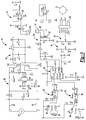
- Figure 3 is a schematic circuit diagram for the electronic controls according to the principles of the present disclosure.
- the vacuum 10 may include a canister 12 and a vacuum head 14 that closes the canister 12.
- the vacuum head may support a drive motor 16.
- the drive motor 16 may support a suction fan 18, which may be provided in a fan chamber 20 of the vacuum head 14.
- the fan chamber 20 may be in fluid communication with an exhaust port 22 and an intake port 24.
- the intake port 24 may be covered by a filter assembly 26 situated in a filter housing 28 of a vacuum head 14.
- a motor 16 when powered up, may rotate the suction fan 18 to draw air into the suction inlet opening 30 and through the canister 12, through the filter assembly 26, through the intake port 24 and into the fan chamber 20.
- the suction fan 18 may push the air in the fan chamber 20 through the exhaust port 22 and out of the vacuum 10.
- a hose 32 can be attached to the inlet opening 30.
- the canister 12 can be supported by wheels 34.
- the wheels 34 can include caster wheels, or the wheels can alternatively be supported by an axle.
- a filter cleaning device 34 is provided including a filter cleaning motor 36 drivingly connected to a filter cleaning mechanism 38.
- the filter cleaning mechanism 38 can take many forms, and can include an eccentrically driven arm 40 having fingers 42 engaging the filter 26.
- the filter cleaning device 34 can be driven to traverse across the filter 26 to cause debris that is stuck to the filter to be loosened up and fall into the canister 12.
- the arm 40 is connected to an eccentric drive member 44 which is connected to motor 36 and, when rotated, causes the arm 40 and fingers 42 to traverse across the surface of the filter 26.
- the electronics 50 generally include a power cord 52 extending from the vacuum and adapted for connection with an AC power source 54.
- the power cord 52 can include a plug 56 having a two-prong or three-prong connection as is known in the art, as is shown in Figure 2 .
- the power cord 52 is connected to a power source circuit 60.
- An electrical isolation circuit 62 is provided in communication with the power source circuit 60 for providing a low voltage output VCC, as will be described in greater detail herein.
- a microcontroller 64 is provided in communication with the electrical isolation circuit 62 for receiving a low voltage supply VCC therefrom. The microcontroller 64 provides control signals to a filter cleaning circuit 66 and a vacuum circuit 68.
- a power tool sense circuit 70 is provided in communication with the microcontroller 64 for providing a signal to the microcontroller 64 regarding operation of a power tool that is plugged into an outlet 72 that can be disposed on the power tool 10.
- the outlet 72 can be connected to the power cord 52 as indicated by nodes L, N.
- a water sense circuit 74 is provided in communication with the microcontroller for providing a signal ("water") to the microcontroller 64 that the water level in the canister 12 has reached a predetermined level for deactivating the vacuum source in order to prevent water from being drawn into the vacuum filter 26.
- a multi position switch such as four position rotary switch 75 can be utilized for providing different activation states of a first micro-switch S1 and a second micro-switch S2 for controlling operation of the vacuum motor 16.
- the switches S1 and S2 are connected to connectors A, B and A, C, respectively, wherein connectors B and C are connected to ratio circuits 76, 78, respectively.
- Connector A provides an input signal to the microcontroller 64 indicative of the activation state of micro-switch S1 and micro-switch S2 in order to provide four modes of operation utilizing the two micro-switches S1 and S2 while providing just a single input into the microcontroller 64.
- Table 1 provides a list of the mode selection possibilities of the four position user switch 75 with micro-switches S1 and S2 in the different activation states.
- Table 1 User Switch Position S1 S2 Microcontroller Input VCC Ratio 1 0 0 0 * VCC 2 0 1 (1/3) * VCC 3 1 0 (4/5) * VCC 4 1 1 (5/8) * VCC
- the ratio circuit 76, 78 provide different ratio input signals as a function of the low voltage supply VCC.
- VCC low voltage supply
- the ratio circuit 76, 78 provide different ratio input signals as a function of the low voltage supply VCC.
- Table 1 when both switch S1 and switch S2 are open, a zero ratio VCC signal is received by the microcontroller 64.
- switch S1 When switch S1 is open and switch S2 is closed, a 1/3 ratio VCC signal is provided.
- a 4/5 VCC ratio signal is provided, and when both switches S1 and S2 are closed, a 5/8 VCC ratio signal is provided to the microcontroller 64.
- the ratios are determined by the resistance levels of resistors R17-R20 provided in the ratio circuits 76, 78.
- Ratios, number of switches, and number of resistors can vary for inputs other than 4. With these four input signals provided at a single microcontroller input, four user selectable modes are provided, thereby simplifying the microcontroller input and reducing the cost of the microcontroller.
- the four user selectable modes can include position (1) vacuum off, power outlet is off, auto filter clean is off and filter clean push button is off; position (2) vacuum on, power outlet is off, auto filter clean is off and filter clean push button is on; position (3) vacuum on, power outlet off, auto filter clean is on and filter clean push button is on; and position (4) (auto mode) vacuum is controlled by outlet, auto filter clean is on and filter clean push button is on.
- These operation modes are exemplary and different modes can be enabled and disabled by the microcontroller 64. Further, more or fewer switch positions can also be employed as well as more micro-switches and ratio circuits can also be utilized that are activated by the user switch for providing even further distinct operation modes.
- a filter clean switch 80 is also provided for providing a signal to the microcontroller 64 for operating the filter cleaning device via activation of the filter cleaning circuit 66.
- the filter cleaning circuit 66 includes an opto-coupler 82 which can be activated by a low voltage signal from the microcontroller 64.
- the opto-coupler 82 provides an activation signal to a triac 84. When the gate of the triac 84 is held active, the triac 84 conducts electricity to the filter cleaning motor 36 for activating the filter cleaning device 34.
- the opto-coupler 82 requires only a low power input for holding the triac 84 active.
- the triac may be held continuously active for a time period then turned inactive, or pulsed active/inactive for a timer period, or the triac may be replaced by an SCR and driven with DC in a similar manner just described.
- the auto filter clean mode will turn off the vacuum for a brief period while the filter cleaning device 34 moves across the filter pleats. This can occur at predetermined intervals while the vacuum is operated continuously and every time the vacuum is turned off.
- the filter clean push button mode when activated by user switch 75 and be pressing the push button 80, will cause the vacuum to turn off for a brief period while the filter cleaning device 34 is operated to move across the filter pleats.
- the microcontroller 64 can also provide a control signal to the vacuum circuit 68.
- the vacuum circuit 68 is provided with an opto-coupler 86 which receives a low voltage signal from the micro-controller 64.
- the opto-coupler 86 can provide an activation voltage to a triac 88 which is held active by the voltage supplied by the opto-coupler 86 to provide electricity to the vacuum motor 16.
- the opto-coupler 86 requires only a low power input for holding the triac 88 active.
- the power tool sense circuit 70 is provided with a current transformer 90 that senses current passing through an electrical connection to the power outlet 72 that supplies power to a power tool that can be plugged into the power outlet 72.
- the current transformer 90 provides a signal to the microcontroller 64 indicative to the activation state of a power tool plugged into the outlet 72.
- the microcontroller 64 can automatically activate the vacuum motor 16 for driving the vacuum source.
- the vacuum motor 16 can be activated to assist in vacuuming debris that is created by the use of the power tool.
- the microcontroller 64 can delay deactivation of the vacuum motor 16 after the power tool is deactivated, to allow for the vacuum 10 to collect debris for a predetermined period of time after the power tool is deactivated.
- the water sense circuit 74 includes a pair of water sense probes 96 disposed within the canister 12 of the vacuum 10. Probes 96 can be connected to vacuum head 14 and can be suspended within the canister 12 below the level of the filter 26.
- a buffer device 98 buffers the high impedance water sense input.
- the microcontroller on its own is unreliable in measuring the high impedance water sense input.
- the output of the buffer device or amplifier 98 goes to an analog input to the microcontroller 64.
- the microcontroller software determines the analog level to detect water sense.
- the water sense probes 96 can be brass probes mounted in the vacuum's canister 12. Water contacting between the probes will be detected by the water sense circuit 74 as a lower impedance.
- the electrical isolation circuit 62 is provided to eliminate shock hazard. Three components provide isolation including the power supply transformer 100 as well as the current transformer 90 and the opto-couplers 82, 86.
- the power supply transformer 100 provides a reduced voltage output from the power source 54.
- a five volt reduced power supply VCC can be provided by the electrical isolation circuit 62 from the AC line voltage source 54.
- the circuit 60 previous to the transformer is the control circuit for the switching supply.
- the transformer provides isolation and is part of the switching supply.
- the five volt regulator takes the isolated control circuit output and reduces it to +5V regulated.
- the low voltage power supply VCC is utilized by the microcontroller 64 for providing signals to the opto-couplers 82, 86 of the filter cleaning circuit 66 and vacuum circuit 68 as well as supplying power to the water sense circuit 74. Furthermore, the ratio switch circuits 76, 78 are supplied with the low voltage VCC power supply.
Landscapes
- Engineering & Computer Science (AREA)
- Mechanical Engineering (AREA)
- Electric Vacuum Cleaner (AREA)
- Control Of Direct Current Motors (AREA)
- Electron Tubes For Measurement (AREA)
- Control Of Motors That Do Not Use Commutators (AREA)
- Cleaning By Liquid Or Steam (AREA)
Applications Claiming Priority (1)
| Application Number | Priority Date | Filing Date | Title |
|---|---|---|---|
| US11/870,923 US7644469B2 (en) | 2007-10-11 | 2007-10-11 | Vacuum electronics isolation method |
Publications (3)
| Publication Number | Publication Date |
|---|---|
| EP2047783A2 true EP2047783A2 (fr) | 2009-04-15 |
| EP2047783A3 EP2047783A3 (fr) | 2012-12-12 |
| EP2047783B1 EP2047783B1 (fr) | 2016-06-22 |
Family
ID=40202097
Family Applications (1)
| Application Number | Title | Priority Date | Filing Date |
|---|---|---|---|
| EP08166021.9A Ceased EP2047783B1 (fr) | 2007-10-11 | 2008-10-07 | Procédé d'isolation électronique sous vide |
Country Status (3)
| Country | Link |
|---|---|
| US (1) | US7644469B2 (fr) |
| EP (1) | EP2047783B1 (fr) |
| CN (1) | CN201328769Y (fr) |
Cited By (2)
| Publication number | Priority date | Publication date | Assignee | Title |
|---|---|---|---|---|
| USD1049525S1 (en) * | 2022-08-30 | 2024-10-29 | Makita Corporation | Vacuum cleaner body |
| USD1058972S1 (en) * | 2022-10-25 | 2025-01-21 | Bissell Inc. | Portable extraction cleaner |
Families Citing this family (24)
| Publication number | Priority date | Publication date | Assignee | Title |
|---|---|---|---|---|
| US8978197B2 (en) * | 2009-03-13 | 2015-03-17 | Lg Electronics Inc. | Vacuum cleaner |
| US8012250B2 (en) | 2005-12-10 | 2011-09-06 | Lg Electronics Inc. | Vacuum cleaner |
| US8404034B2 (en) | 2005-12-10 | 2013-03-26 | Lg Electronics Inc. | Vacuum cleaner and method of controlling the same |
| US7749295B2 (en) * | 2005-12-10 | 2010-07-06 | Lg Electronics Inc. | Vacuum cleaner with removable dust collector, and methods of operating the same |
| US7987551B2 (en) * | 2005-12-10 | 2011-08-02 | Lg Electronics Inc. | Vacuum cleaner |
| US7882592B2 (en) * | 2005-12-10 | 2011-02-08 | Lg Electronics Inc. | Vacuum cleaner |
| US8281455B2 (en) * | 2005-12-10 | 2012-10-09 | Lg Electronics Inc. | Vacuum cleaner |
| US8544143B2 (en) * | 2005-12-10 | 2013-10-01 | Lg Electronics Inc. | Vacuum cleaner with removable dust collector, and methods of operating the same |
| EP1949842B1 (fr) * | 2007-01-24 | 2015-03-04 | LG Electronics Inc. | Aspirateur |
| US9776296B2 (en) | 2008-05-09 | 2017-10-03 | Milwaukee Electric Tool Corporation | Power tool dust collector |
| US8967923B2 (en) | 2012-01-13 | 2015-03-03 | Aeg Electric Tools Gmbh | Dust suction device for drilling machine |
| US7992252B2 (en) * | 2009-02-12 | 2011-08-09 | Lg Electronics Inc. | Vacuum cleaner |
| US8151409B2 (en) * | 2009-02-26 | 2012-04-10 | Lg Electronics Inc. | Vacuum cleaner |
| US8713752B2 (en) * | 2009-03-13 | 2014-05-06 | Lg Electronics Inc. | Vacuum cleaner |
| US8997308B2 (en) | 2012-07-24 | 2015-04-07 | Koblenz Electricia S.A. de C.V. | Wet/dry vacuum cleaner |
| US9107550B2 (en) | 2013-09-27 | 2015-08-18 | Black & Decker Inc. | Compact vacuum and sander |
| JP6229849B2 (ja) * | 2014-09-17 | 2017-11-15 | 日立工機株式会社 | 集塵機 |
| US11235433B2 (en) | 2017-12-22 | 2022-02-01 | Milwaukee Electric Tool Corporation | Dust collector with filter cleaning mechanism |
| USD877435S1 (en) * | 2018-05-08 | 2020-03-03 | Shop Vac Corporation | Vacuum cleaner |
| DE102018215308A1 (de) | 2018-09-10 | 2020-03-12 | Robert Bosch Gmbh | Staubsaugvorrichtung |
| CN215968574U (zh) | 2018-11-19 | 2022-03-08 | 米沃奇电动工具公司 | 适于与手持式电动工具一起使用的集尘器 |
| WO2021195339A1 (fr) | 2020-03-25 | 2021-09-30 | Milwaukee Electric Tool Corporation | Ensemble collecteur de poussière |
| US12357136B2 (en) | 2020-11-19 | 2025-07-15 | Milwaukee Electric Tool Corporation | Portable dust extractor |
| WO2022177905A1 (fr) | 2021-02-16 | 2022-08-25 | Milwaukee Electric Tool Corporation | Communication entre un extracteur de poussière sans fil et un outil électrique |
Citations (5)
| Publication number | Priority date | Publication date | Assignee | Title |
|---|---|---|---|---|
| EP0349888A2 (fr) | 1988-07-05 | 1990-01-10 | BSG-Schalttechnik GmbH & Co. KG | Appareil avec mise sous tension automatique pour une unité additionelle en liaison avec la mise en marche d'une unité principale |
| US6044519A (en) | 1995-12-07 | 2000-04-04 | Emerson Electric Co. | Portable electric tool vacuum cleaner control |
| EP1083652A2 (fr) | 1999-09-07 | 2001-03-14 | Shop Vac Corporation | Circuit de commande de commutation intelligent |
| US6347430B1 (en) | 1996-07-12 | 2002-02-19 | Shop Vac Corporation | Self-evacuating vacuum cleaner |
| WO2007083844A1 (fr) | 2006-01-20 | 2007-07-26 | Hitachi Koki Co., Ltd. | Collecteur à poussières pour la détection et l'élimination des poussières du filtre |
Family Cites Families (52)
| Publication number | Priority date | Publication date | Assignee | Title |
|---|---|---|---|---|
| US1864622A (en) * | 1930-10-25 | 1932-06-28 | Alfred W Sutherland | Apparatus for cleaning vacuum cleaner bags |
| US2522882A (en) * | 1945-08-14 | 1950-09-19 | Electrolux Corp | Vacuum cleaner |
| FR957814A (fr) * | 1946-07-12 | 1950-02-25 | ||
| US3236032A (en) * | 1962-01-22 | 1966-02-22 | Hitachi Ltd | Vacuum cleaner with filter cleaning means |
| US3320726A (en) * | 1966-04-18 | 1967-05-23 | Parks Cramer Co | Traveling textile cleaner with forced air filter cleaning means |
| DE1964261C3 (de) * | 1969-12-22 | 1973-06-28 | Matsushita Electric Ind Co Ltd | Elektromotorisch angetriebener Staubsauger |
| US3708962A (en) * | 1970-03-20 | 1973-01-09 | Sanyo Electric Co | Vacuum cleaner |
| US3656083A (en) * | 1970-09-01 | 1972-04-11 | Richard G Brook | Electrical safety device |
| US3695006A (en) * | 1970-10-23 | 1972-10-03 | Dynamics Corp America | Vacuum cleaner |
| US3936904A (en) * | 1974-06-03 | 1976-02-10 | Whirlpool Corporation | Vacuum cleaner clogged condition indicator |
| US4021879A (en) * | 1975-11-28 | 1977-05-10 | Consolidated Foods Corporation | Constant performance vacuum cleaner |
| US4070078A (en) * | 1977-03-02 | 1978-01-24 | Reliance Products Corporation | Safety cover for an electrical outlet |
| US4266257A (en) * | 1978-10-02 | 1981-05-05 | Johnson Controls, Inc. | Motor over-heating protection circuit |
| US4302624A (en) * | 1980-05-16 | 1981-11-24 | Newman Fredric M | Electric wall outlet protector |
| US4357729A (en) * | 1981-01-26 | 1982-11-09 | Whirlpool Corporation | Vacuum cleaner control |
| US4370690A (en) * | 1981-02-06 | 1983-01-25 | Whirlpool Corporation | Vacuum cleaner control |
| EP0188294A3 (fr) * | 1981-10-26 | 1986-12-30 | Pico Electronics Limited | Commande d'appareil électrique |
| US4398316A (en) * | 1982-01-13 | 1983-08-16 | The Scott & Fetzer Company | Speed selector switch |
| US4611365A (en) * | 1983-02-12 | 1986-09-16 | Matsushita Electric Industrial Co., Ltd. | Vacuum cleaner |
| DE3410817A1 (de) | 1984-03-23 | 1985-10-03 | Esta Apparatebau GmbH & Co KG, 7913 Senden | Reinigungsgeraet fuer schwimmbaeder oder dgl. |
| US4654924A (en) * | 1985-12-31 | 1987-04-07 | Whirlpool Corporation | Microcomputer control system for a canister vacuum cleaner |
| DE8713636U1 (de) * | 1986-10-14 | 1987-12-10 | Alfred Kärcher GmbH & Co, 7057 Winnenden | Staubsauger |
| US4825140A (en) * | 1988-05-03 | 1989-04-25 | St Louis Raymond F | Power tool/vacumm cleaner power control |
| US5099157A (en) * | 1988-06-10 | 1992-03-24 | Milwaukee Electric Tool Corporation | Master/slave circuit employing triacs |
| DE3902647A1 (de) * | 1989-01-21 | 1990-08-02 | Interlava Ag | Vorrichtung zur automatischen saugleistungssteuerung eines staubsaugers |
| SE463070B (sv) * | 1989-02-14 | 1990-10-08 | Electrolux Ab | Anordning vid en dammsugare |
| JP2983658B2 (ja) * | 1991-02-14 | 1999-11-29 | 三洋電機株式会社 | 電気掃除機 |
| JP2553485Y2 (ja) * | 1991-04-19 | 1997-11-05 | 株式会社マキタ | 集塵機の外部電源供給機構 |
| JPH0662991A (ja) * | 1992-08-21 | 1994-03-08 | Yashima Denki Co Ltd | 電気掃除機 |
| DK140892D0 (da) * | 1992-11-24 | 1992-11-24 | Lego As | Elektrisk omskifter |
| DE4327070C1 (de) * | 1993-08-12 | 1995-04-06 | Gerhard Kurz | Vorrichtung zur Regelung der Leistungsaufnahme eines Staubsaugers |
| US5541457A (en) * | 1995-06-12 | 1996-07-30 | Morrow; Rodney J. | Electrical current actuated accessory outlet |
| US5747973A (en) * | 1996-12-11 | 1998-05-05 | Shop Vac Corporation | Current regulating switch circuit |
| US6029309A (en) * | 1997-04-08 | 2000-02-29 | Yashima Electric Co., Ltd. | Vacuum cleaner with dust bag fill detector |
| US5955791A (en) * | 1997-04-14 | 1999-09-21 | Irlander; James E. | Master/slave circuit for dust collector |
| US6008608A (en) * | 1997-04-18 | 1999-12-28 | Emerson Electric Co. | User operated switch and speed control device for a wet/dry vacuum |
| US6026539A (en) * | 1998-03-04 | 2000-02-22 | Bissell Homecare, Inc. | Upright vacuum cleaner with full bag and clogged filter indicators thereon |
| DE19813434A1 (de) * | 1998-03-27 | 1999-09-30 | Proair Geraetebau Gmbh | Naßsauger |
| CA2281318C (fr) * | 1998-09-04 | 2011-08-09 | Beamco, Inc. | Circuit et methode securitaires de commande de moteur de classe 2 adaptes a la commande electrique d'un moteur de systeme d'aspirateur central et d'un moteur d'agitateur |
| KR100413988B1 (ko) * | 2000-03-24 | 2004-01-07 | 샤프 가부시키가이샤 | 전기 진공 청소기 |
| US6457205B1 (en) * | 2000-05-24 | 2002-10-01 | Fantom Technologies Inc. | Vacuum cleaner having a plurality of power modes |
| US6569218B2 (en) * | 2001-03-08 | 2003-05-27 | David Edmond Dudley | Self spin-cleaning canister vacuum |
| WO2002094077A1 (fr) * | 2001-05-21 | 2002-11-28 | Tennant Company | Systeme de commande pour appareil d'entretien des sols |
| DE10164204A1 (de) * | 2001-12-27 | 2003-07-17 | Siemens Linear Motor Systems G | Schutzeinrichtung für Elektromotor mit Sensor und Auswerteeinheit |
| US7152277B2 (en) * | 2003-03-13 | 2006-12-26 | Samsung Gwangju Electronics Co., Ltd. | Filter assembly for cyclone type dust collecting apparatus of a vacuum cleaner |
| KR100518804B1 (ko) * | 2003-03-31 | 2005-10-06 | 삼성광주전자 주식회사 | 사이클론집진장치의 필터청소기구 |
| US6758874B1 (en) * | 2003-05-09 | 2004-07-06 | John P. Hunter, Jr. | Rotating filter feature for wet/dry vacuum cleaner |
| GB0318284D0 (en) * | 2003-08-05 | 2003-09-10 | Black & Decker Inc | Hand-held vacuum cleaner |
| US7208024B2 (en) * | 2003-12-08 | 2007-04-24 | The Hoover Company | Floor care appliance with filter cleaning system |
| US7351269B2 (en) * | 2003-12-22 | 2008-04-01 | Lau Kwok Yau | Self cleaning filter and vacuum incorporating same |
| KR100539762B1 (ko) * | 2004-03-09 | 2006-01-10 | 엘지전자 주식회사 | 진공청소기의 필터 청소 장치 |
| KR100585692B1 (ko) * | 2004-04-06 | 2006-06-07 | 엘지전자 주식회사 | 진공청소기의 먼지통 |
-
2007
- 2007-10-11 US US11/870,923 patent/US7644469B2/en not_active Expired - Fee Related
-
2008
- 2008-10-07 EP EP08166021.9A patent/EP2047783B1/fr not_active Ceased
- 2008-10-13 CN CNU2008201773670U patent/CN201328769Y/zh not_active Expired - Fee Related
Patent Citations (5)
| Publication number | Priority date | Publication date | Assignee | Title |
|---|---|---|---|---|
| EP0349888A2 (fr) | 1988-07-05 | 1990-01-10 | BSG-Schalttechnik GmbH & Co. KG | Appareil avec mise sous tension automatique pour une unité additionelle en liaison avec la mise en marche d'une unité principale |
| US6044519A (en) | 1995-12-07 | 2000-04-04 | Emerson Electric Co. | Portable electric tool vacuum cleaner control |
| US6347430B1 (en) | 1996-07-12 | 2002-02-19 | Shop Vac Corporation | Self-evacuating vacuum cleaner |
| EP1083652A2 (fr) | 1999-09-07 | 2001-03-14 | Shop Vac Corporation | Circuit de commande de commutation intelligent |
| WO2007083844A1 (fr) | 2006-01-20 | 2007-07-26 | Hitachi Koki Co., Ltd. | Collecteur à poussières pour la détection et l'élimination des poussières du filtre |
Cited By (2)
| Publication number | Priority date | Publication date | Assignee | Title |
|---|---|---|---|---|
| USD1049525S1 (en) * | 2022-08-30 | 2024-10-29 | Makita Corporation | Vacuum cleaner body |
| USD1058972S1 (en) * | 2022-10-25 | 2025-01-21 | Bissell Inc. | Portable extraction cleaner |
Also Published As
| Publication number | Publication date |
|---|---|
| EP2047783A3 (fr) | 2012-12-12 |
| CN201328769Y (zh) | 2009-10-21 |
| US20090094777A1 (en) | 2009-04-16 |
| EP2047783B1 (fr) | 2016-06-22 |
| US7644469B2 (en) | 2010-01-12 |
Similar Documents
| Publication | Publication Date | Title |
|---|---|---|
| US7644469B2 (en) | Vacuum electronics isolation method | |
| EP2047784B1 (fr) | Système de détection du commutateur électronique d'un aspirateur | |
| EP2055221B1 (fr) | Aspirateur industriel avec un circuit électronique de détection d'eau | |
| EP1955637B1 (fr) | Capteur d'outil électronique sous vide | |
| US8443485B2 (en) | Outlet box for power tool sense | |
| US20260048354A1 (en) | Combination vacuum and air purifier system and method | |
| KR200170960Y1 (ko) | 가변가습기발생 진공청소기 | |
| JP3874175B2 (ja) | 電気掃除機 | |
| JPH02152427A (ja) | 電気掃除機 | |
| JP2002369777A (ja) | 電気掃除機 | |
| KR970011918B1 (ko) | 진공청소기의 운전제어장치 | |
| KR970005516B1 (ko) | 진공청소기에서의 흡입먼지 유무에 따른 구동전원 자동차단장치 및 그 방법 | |
| JP3285028B2 (ja) | 電気掃除機 | |
| JP3874176B2 (ja) | 電気掃除機 | |
| KR960007468B1 (ko) | 진공청소기의 압력센서 감도절환/고장감지장치 및 방법 | |
| JP2010194208A (ja) | 電気掃除機 | |
| JPH0121977B2 (fr) | ||
| JPH0618545B2 (ja) | 電気掃除機 | |
| JPH01110338A (ja) | 電気掃除機 | |
| JP2001340277A (ja) | 電気掃除機 | |
| JPH033959U (fr) | ||
| JPH0822267B2 (ja) | 電気掃除機 | |
| JPH049129A (ja) | 電気掃除機 | |
| JP2002045312A (ja) | 電気掃除機 |
Legal Events
| Date | Code | Title | Description |
|---|---|---|---|
| PUAI | Public reference made under article 153(3) epc to a published international application that has entered the european phase |
Free format text: ORIGINAL CODE: 0009012 |
|
| AK | Designated contracting states |
Kind code of ref document: A2 Designated state(s): AT BE BG CH CY CZ DE DK EE ES FI FR GB GR HR HU IE IS IT LI LT LU LV MC MT NL NO PL PT RO SE SI SK TR |
|
| AX | Request for extension of the european patent |
Extension state: AL BA MK RS |
|
| RIC1 | Information provided on ipc code assigned before grant |
Ipc: A47L 7/00 20060101ALI20110419BHEP Ipc: A47L 9/28 20060101AFI20090116BHEP |
|
| PUAL | Search report despatched |
Free format text: ORIGINAL CODE: 0009013 |
|
| AK | Designated contracting states |
Kind code of ref document: A3 Designated state(s): AT BE BG CH CY CZ DE DK EE ES FI FR GB GR HR HU IE IS IT LI LT LU LV MC MT NL NO PL PT RO SE SI SK TR |
|
| AX | Request for extension of the european patent |
Extension state: AL BA MK RS |
|
| RIC1 | Information provided on ipc code assigned before grant |
Ipc: A47L 9/28 20060101AFI20121105BHEP Ipc: A47L 5/36 20060101ALI20121105BHEP Ipc: A47L 7/00 20060101ALI20121105BHEP Ipc: A47L 9/20 20060101ALI20121105BHEP |
|
| 17P | Request for examination filed |
Effective date: 20130604 |
|
| RBV | Designated contracting states (corrected) |
Designated state(s): AT BE BG CH CY CZ DE DK EE ES FI FR GB GR HR HU IE IS IT LI LT LU LV MC MT NL NO PL PT RO SE SI SK TR |
|
| AKX | Designation fees paid |
Designated state(s): DE GB |
|
| GRAP | Despatch of communication of intention to grant a patent |
Free format text: ORIGINAL CODE: EPIDOSNIGR1 |
|
| RIC1 | Information provided on ipc code assigned before grant |
Ipc: A47L 5/36 20060101ALI20160324BHEP Ipc: A47L 9/20 20060101ALI20160324BHEP Ipc: A47L 9/28 20060101AFI20160324BHEP Ipc: A47L 7/00 20060101ALI20160324BHEP |
|
| GRAS | Grant fee paid |
Free format text: ORIGINAL CODE: EPIDOSNIGR3 |
|
| INTG | Intention to grant announced |
Effective date: 20160421 |
|
| GRAA | (expected) grant |
Free format text: ORIGINAL CODE: 0009210 |
|
| AK | Designated contracting states |
Kind code of ref document: B1 Designated state(s): DE GB |
|
| REG | Reference to a national code |
Ref country code: GB Ref legal event code: FG4D |
|
| REG | Reference to a national code |
Ref country code: DE Ref legal event code: R096 Ref document number: 602008044767 Country of ref document: DE |
|
| REG | Reference to a national code |
Ref country code: DE Ref legal event code: R097 Ref document number: 602008044767 Country of ref document: DE |
|
| PLBE | No opposition filed within time limit |
Free format text: ORIGINAL CODE: 0009261 |
|
| STAA | Information on the status of an ep patent application or granted ep patent |
Free format text: STATUS: NO OPPOSITION FILED WITHIN TIME LIMIT |
|
| 26N | No opposition filed |
Effective date: 20170323 |
|
| PGFP | Annual fee paid to national office [announced via postgrant information from national office to epo] |
Ref country code: GB Payment date: 20210901 Year of fee payment: 14 |
|
| PGFP | Annual fee paid to national office [announced via postgrant information from national office to epo] |
Ref country code: DE Payment date: 20210824 Year of fee payment: 14 |
|
| REG | Reference to a national code |
Ref country code: DE Ref legal event code: R119 Ref document number: 602008044767 Country of ref document: DE |
|
| GBPC | Gb: european patent ceased through non-payment of renewal fee |
Effective date: 20221007 |
|
| PG25 | Lapsed in a contracting state [announced via postgrant information from national office to epo] |
Ref country code: DE Free format text: LAPSE BECAUSE OF NON-PAYMENT OF DUE FEES Effective date: 20230503 |
|
| PG25 | Lapsed in a contracting state [announced via postgrant information from national office to epo] |
Ref country code: GB Free format text: LAPSE BECAUSE OF NON-PAYMENT OF DUE FEES Effective date: 20221007 |