EP2047896A2 - Filtre à manche, panier d'appui pour celui-ci et installation de filtre à manche - Google Patents
Filtre à manche, panier d'appui pour celui-ci et installation de filtre à manche Download PDFInfo
- Publication number
- EP2047896A2 EP2047896A2 EP08016934A EP08016934A EP2047896A2 EP 2047896 A2 EP2047896 A2 EP 2047896A2 EP 08016934 A EP08016934 A EP 08016934A EP 08016934 A EP08016934 A EP 08016934A EP 2047896 A2 EP2047896 A2 EP 2047896A2
- Authority
- EP
- European Patent Office
- Prior art keywords
- filter
- filter tube
- bag
- tube
- support basket
- Prior art date
- Legal status (The legal status is an assumption and is not a legal conclusion. Google has not performed a legal analysis and makes no representation as to the accuracy of the status listed.)
- Withdrawn
Links
Images




Classifications
-
- B—PERFORMING OPERATIONS; TRANSPORTING
- B01—PHYSICAL OR CHEMICAL PROCESSES OR APPARATUS IN GENERAL
- B01D—SEPARATION
- B01D46/00—Filters or filtering processes specially modified for separating dispersed particles from gases or vapours
- B01D46/02—Particle separators, e.g. dust precipitators, having hollow filters made of flexible material
- B01D46/06—Particle separators, e.g. dust precipitators, having hollow filters made of flexible material with means keeping the working surfaces flat
-
- B—PERFORMING OPERATIONS; TRANSPORTING
- B01—PHYSICAL OR CHEMICAL PROCESSES OR APPARATUS IN GENERAL
- B01D—SEPARATION
- B01D46/00—Filters or filtering processes specially modified for separating dispersed particles from gases or vapours
- B01D46/02—Particle separators, e.g. dust precipitators, having hollow filters made of flexible material
-
- B—PERFORMING OPERATIONS; TRANSPORTING
- B01—PHYSICAL OR CHEMICAL PROCESSES OR APPARATUS IN GENERAL
- B01D—SEPARATION
- B01D46/00—Filters or filtering processes specially modified for separating dispersed particles from gases or vapours
- B01D46/56—Filters or filtering processes specially modified for separating dispersed particles from gases or vapours with multiple filtering elements, characterised by their mutual disposition
- B01D46/58—Filters or filtering processes specially modified for separating dispersed particles from gases or vapours with multiple filtering elements, characterised by their mutual disposition connected in parallel
- B01D46/60—Filters or filtering processes specially modified for separating dispersed particles from gases or vapours with multiple filtering elements, characterised by their mutual disposition connected in parallel arranged concentrically or coaxially
Definitions
- the invention relates to a bag filter for bag filter systems for separating solids, especially chips and / or dust from an air / solid mixture, according to the preamble of claim 1. Furthermore, the invention relates to a support basket for a bag filter according to the preamble of claim 11 and a bag filter according to the preamble of claim 14.
- Bag filter systems of the type mentioned here are mainly used in wood or paper processing use. These are stationary or mobile systems for filtering and / or separating dusts, shredded paper, sawdust or wood shavings.
- Known bag filter systems have a filter bag hose filter.
- a negative pressure is generated, whereby solids to be filtered off settle on the outside of the wall of the respective filter bag and the cleaned air can be sucked through the interior of the filter bag.
- By supporting body of the respective filter hose is supported against the negative pressure in the interior.
- the filter performance of bag filter systems is crucially dependent on the total surface area of all filter bags of the bag filter system.
- the number of filter bags must be increased, whereby the outer dimensions of known bag filter systems increase considerably with increasing filter performance.
- the invention is therefore an object of the invention to provide a bag filter, a bag filter and a support body for a bag filter, which can achieve higher filter performance.
- a bag filter for solving the above-mentioned problem has the features of claim 1. Because the bag filter has at least one inner filter tube in addition to an outer filter tube, it has a larger effective filter area. The space requirement of the bag filter is not increased because the additional filter surface in the interior of the bag filter, namely in the outer filter tube is created.
- the bag filter has only one inner filter tube, it is designed in the manner of a double filter tube. But it is also conceivable to provide several inner tubes. For example, if three inner filter bags are housed in the outer filter bag, there are two double bag filters nested together. The effective filter area is more than doubled, almost fourfold.
- the annulus between the filter bags is closed at one end, preferably at the end opposite the suction end of the bag filter.
- the annular space at the end opposite the suction end is closed by an annular cap having a central opening, whereby the air-solid mixture to be filtered also get into the interior of the inner filter tube can.
- this annular cap or other closure object also serves to hold the ends of the filter bags.
- the suction end of both the outer filter tube and the inner filter tube is connected to the annular cap by clamping, gluing, sewing and / or knotting.
- the at least one inner filter tube can be formed both cylindrical and conical. In both cases, longitudinal central axes of the outer filter tube and the inner filter tube lie on a common line, so that the outer filter tube concentrically surrounds the respective inner filter tube. In length, the filter bags are preferably formed the same.
- the inner filter tube may be slightly shorter than the outer filter tube for fluidic and assembly reasons, in particular if the inner filter tube is cylindrical.
- the support basket is designed for arrangement between the outer filter tube and the inner filter tube. Such a support basket is then in the annular space between the different sized filter bags. Because of this arrangement and training, both the outer filter tube from the inside and the inner filter tube can be supported from the outside with a single support cage, so that when exposed to the annular space with vacuum for sucking the filtered air concentric with each other extending filter tubes are spaced apart and not be sucked together can, thereby effectively filter surface of the bag filter would be lost.
- the support basket In the length of the support basket is preferably formed so that it supports at least the inner filter tube over its entire length, preferably also the outer filter tube. Then the support basket can serve to hang the entire bag filter on a ceiling wall of the bag filter system.
- the arranged in the annular space between the filter bags support basket has for supporting the inner filter tube longitudinal webs which are arranged so that their inwardly directed longitudinal edges support the inner filter tube on the outside.
- the longitudinal webs are arranged or formed such that their longitudinal edges supporting the inner filter tube lie on an imaginary cylinder jacket surface, which preferably corresponds to the diameter of the inner filter tube.
- a support basket for solving the above-mentioned problem has the features of claim 11.
- This support basket has in addition to a grid-like support structure via longitudinal webs with pointing into the interior of the support structure longitudinal edges.
- the support structure serves to support an outer filter tube of a bag filter, while the inwardly directed longitudinal edges of the longitudinal webs serve for the outside support of an inner filter tube.
- two concentric filter tubes of a double filter tube are supported so that between the filter surfaces of the outer filter tube and the inner filter tube a circumferential annular space for sucking the filtered air remains so that the inner filter tube and the outer filter tube do not touch.
- a support basket can be produced with a simple injection mold made of plastic by injection molding.
- the mutually parallel longitudinal webs are dimensioned in particular in their width so that their inwardly directed longitudinal edges are all on a common imaginary cylindrical surface, said cylindrical surface preferably corresponds to the cylindrical filter surface of the inner filter tube, but may be slightly larger or smaller.
- the preferably made of plastic support basket may be formed one or more parts.
- a multi-part support basket consists for example of two half-shells, which are manufactured separately and before mounting the bag filter solvable or insoluble are connected, for example by snapping, gluing or welding.
- a one-piece support basket can be formed from two shells connected to adjacent longitudinal edges. The half-shells are connected by joints or as hinges, in particular a film hinge, firmly together. The two half-shells are made in unfolded juxtaposed condition. The longitudinal webs of the two half-shells extend parallel to each other, whereby the unfolded support basket can be easily produced by injection molding.
- the half-shells are folded around the hinge axis and detachably or non-detachably connected to the outer longitudinal edges, for example by clicking. Due to the subsequent folding of the half-shells, the still unfolded support basket takes up relatively little space for transport, because a plurality of unfolded support basket can be stacked in one another. It is also conceivable, however, to form the support basket as a closed, one-piece cage.
- a bag filter system for solving the above-mentioned problem has the features of claim 14.
- Such a bag filter system is characterized by a large number of previously described bag filters with support baskets.
- the bag filters are suspended side by side and one behind the other in the bag filter system, in particular a top wall thereof, the longitudinal center axes of the bag filter are seen in plan view of the bag filter system distributed on a grid, so that in the housing of the bag filter system, the filter bags are suspended side by side and one behind the other.
- the filter bags are suspended with their preferably upper suction on the top wall of the bag filter system.
- filter bags made of an outer filter tube and an inner filter tube in which the suction-side ends of the inner filter tubes are closed, it is conceivable to hang these closed ends of the inner filter tubes on a movable support, such as rods. This allows the filter bags from time to time shaken or vibrated to free them from the outside of the filter bags, both the inner filter tubes and the outer filter tubes, adhering dust or the like.
- bag filters are designed as double bag filters, each with an external filter hose and an inner filter bag, approximately twice the filter capacity is available compared to a conventional bag filter system with bag filters made from external filter bags only. An even greater increase in performance is achievable if the bag filters are formed of more than two concentric nested filter bags, for example, three filter bags or four filter bags.
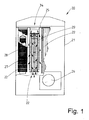
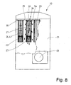
- the Fig. 1 and 8th schematically show a side view of a bag filter unit 20 for separating solids, especially dust, chips and / or paper particles from an air / solid mixture.
- the bag filter system 20 may be stationary or mobile. It is preferably used in wood and paper processing companies, such as carpentry or printing.
- the bag filter unit 20 has a box-like, closed housing 21.
- a plurality of preferably identical bag filters 22 and 23 are suspended in a grid-like manner, that is to say with a longitudinal central axis 24 extending perpendicularly.
- the bag filters 22 and 23 are suspended on a ceiling wall, in particular an intermediate ceiling 25, in the housing 21 of the bag filter system 20.
- the bag filter 20 of the Fig. 1 and 8th differ with regard to the design of the bag filters 22 and 23.
- the same bag filters 22 FIG. Fig. 1
- 23 Fig. 8
- the in the Fig. 1 shown bag filter 20 has a side intake 26.
- the intake manifold 26 Into the housing 21 of the bag filter system 20 passes through the intake manifold 26 sucked dust, so with chips, paper particles or other solids offset air through at least one fan, not shown, 25 air is sucked through the false ceiling and thereby in the bag filters 22, 23 a Suction air flow generated.
- the air-solid mixture is sucked to the bag filters 22, 23 and filtered by the air is sucked through the bag filters 22, 23, wherein the solids, such as chips or paper particles, are held on the filter surfaces of the bag filters 22, 23.
- the solid particles drop with time from the bag filters 22, 23 and collect in a collecting container, not shown, for the solid particles below the bag filters 22, 23 in the housing 21.
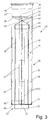
- the Fig. 2 to 5 and 7 show a first embodiment of the hose filter 20 according to the invention, of which several in the bag filter system 20 of Fig. 1 are arranged hanging.
- the bag filter 22 shown is designed as a double-tube filter, namely has a cylindrical outer filter tube 27 and a smaller diameter cylindrical inner filter tube 28.
- the filter tubes 27 and 28 are preferably formed of the same material. This may be a textile material in the form of a fabric or a fleece, in particular a needle felt. It is also conceivable to form the filter bags 27 and 28 from a sieve-like material, for example a wire mesh or a fine plastic mesh.
- the inner filter tube 28 is concentrically arranged in a larger diameter outer filter tube 27, so that the longitudinal center axes of the filter bags 27, 28 overlap, namely lie on the longitudinal center axis 24 of the bag filter 22.
- a circumferential annular space 29 the cross section over the entire length of the bag filter 22 is the same, because the outer filter tube 27 and the inner filter tube 28 via have cylindrical filter surfaces.
- the inner filter tube 28 is slightly shorter than the outer filter tube 27 (FIG. Fig. 3 ). A lower end of the annular space 29 between the filter bags 27, 28 is closed.
- annular cap 33 with a circular surface 30 which is perpendicular to the longitudinal central axis 24 and has an upwardly facing outer collar 31 and a downwardly facing cylindrical inner collar 32 of smaller diameter.
- the inner collar 32 surrounds a central circular opening of the cap 33. This opening corresponds approximately to the diameter of the inner filter tube 28.
- the annular cap 33 is preferably thin-walled made of plastic, in particular thermoplastic.
- a narrow lower end region of the outer filter tube 27 is connected to the outer collar 31 of the cap 33, while a narrow end region of the inner filter tube 28 is connected in the inner collar 32.
- the connection of the filter bags 27, 28 with the cap 33 is preferably carried out by sewing. But other connection techniques may be considered.
- the outer filter tube 27 and the inner filter tube 28 of the bag filter 22 are held by a single arranged in the annular space 29 support basket 36 at a distance.
- the preferably made of plastic integrally support basket 36 so supports the outer filter tube 27 from the inside and the inner filter tube 28 from the outside, so that due to the negative pressure, the purified air from the annular space 29 between the outer filter tube 27 and the inner filter tube 28, the Filterwandened the filter bags 27 and 28 are held by the support basket 36 around and over the entire length at a distance.
- the support basket 36 has a grid-like support structure of a plurality of circumferentially spaced longitudinal bars 37 and these cohesive in the longitudinal direction of the support basket 36 spaced rings 38.
- the longitudinal bars 37 are distributed on an imaginary cylinder jacket and extend at the same distance parallel to the longitudinal central axis 24 of the bag filter 22.
- Die spaced rings 38 intersect the longitudinal center axis 24 vertically.
- At least at the longitudinal bars 37 of the outer filter tube 27 is located from the outside, so that the longitudinal bars 37 support the outer filter tube 27 from the inside.
- the rings 38 abut against the inner circumferential surface of the outer filter tube 27 in order to support this in addition.
- the support basket 36 also has a plurality of evenly distributed on its circumference longitudinal webs 39. Free longitudinal edges 40 of the longitudinal webs 39 point into the interior of the bag filter 22. These longitudinal edges 40 serve to support the outside of the inner filter tube 28.
- the longitudinal webs 39 are formed, in particular in width so dimensioned that the longitudinal edges 40 of all longitudinal webs 39 on a common imaginary Cylindrical surface 42 are located, which corresponds to the outer circumference of the inner filter tube 28, namely approximately equal to the outer diameter of the inner filter tube 28 or is slightly larger or smaller.
- the longitudinal webs 39 are connected in one piece with at least the rings 38 to form the overall one-piece support basket 36. Preferably, the longitudinal webs 39 are also connected to the longitudinal bars 37.
- the longitudinal webs 39 can simultaneously form the longitudinal bars 37. As the 4 and 5 show, all longitudinal webs 39 are parallel to each other. In addition, the longitudinal webs 39 extend parallel to a longitudinal center plane 41 of the support basket 36, wherein two longitudinal webs 39 can also lie on the longitudinal center plane 41. In width, the longitudinal webs 39 are dimensioned differently, in such a way that all longitudinal edges 40 lie on an imaginary cylindrical surface 42. As a result, the longitudinal edges 40 can support the cylindrical inner filter tube 28 from the outside, so that it retains its cylindrical shape at least in the areas of the abutment at the longitudinal edges 40, namely, is supported accordingly.
- the support basket 36 consists of two equal up and collapsible half-shells 43, 44.
- Die Fig. 7 shows the unfolded support basket 36 with adjacent half-shells 43, 44.
- the support basket 36 is made of plastic by injection molding.
- the support basket 36 can also be transported to save space.
- the two half-shells 43, 44 are produced in one piece, namely at adjacent longitudinal edges 45 by a film hinge 46 connected.
- outer longitudinal edges 47 of the half-shells 43, 44 have suitable closure means, which, for example latching with a closed support basket 36, the collapsed half-shells 43, 44 are connectable to the outer longitudinal edges 47. This can be a detachable or non-detachable connection.
- the Fig. 7 indicates that in the production of the support basket 36 with unfolded half-shells 43, 44 all longitudinal webs 39 extend parallel to each other, whereby the support basket 36 can be easily produced by injection molding.
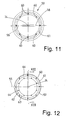
- the Fig. 6 shows an alternative embodiment of the support basket 36 with the same, especially equal width longitudinal webs 39 which are directed radially, so with the longitudinal edges 40 to the longitudinal central axis 24 of the support basket 36 point.
- the support basket 36 shown in the figure with radially directed longitudinal webs 39 can like that in the Fig. 4, 5 and 7 shown support basket 36 may be formed of twoprogressively- and collapsible half-shells 43, 44, but also closed by he can not be opened.
- the support basket 36 is slightly shorter than the outer filter tube 27 formed by ending just before the retaining collar 35. It is also conceivable to make the support basket 36 longer, so that an end region of the support basket 36 is supported in the retaining collar 35 or the support basket 36 integrally formed on the retaining collar 35.
- the inner filter tube 28 is formed somewhat shorter than the support basket 36 (shown here bag filter 22 (FIG. Fig. 3 ).
- the end of the inner filter tube 28 pointing to the suction end 34 of the bag filter 22 is closed by a cap 48.
- This closure cap 48 is preferably formed from thin-walled plastic and has a cylindrical collar 49 and a sealing cone formed on the side facing the suction end 34 on the collar 49 50.
- An end portion of the inner filter tube 28 is connected to the closure cap 48, just as the cap 33 is connected to the filter tubes 27 and 28, for example, by sewing.
- the suction end 34 facing end of the inner filter tube 28 with a attached cap 48 is held in the radial direction in the support basket 36.
- the inner filter tube 28 In the axial direction of the inner filter tube 28 is tied to the support basket 36, for example by at least one cable tie 51 which passes through an eyelet 52 at the top of the cap 48 and holes 53 in at least some longitudinal webs 39 therethrough ( Fig. 3 ).
- a cable tie 51 which passes through an eyelet 52 at the top of the cap 48 and holes 53 in at least some longitudinal webs 39 therethrough ( Fig. 3 ).
- a shaking device By occasional pulsating and / or oscillating movements of the shaking device, at least the inner filter tube 28, preferably at the same time also the outer filter tube 27, freed of adhering solid particles which have been filtered out of the air.
- FIG. 1 the air flow through the bag filter 22 of the bag filter system 20 is shown.
- a negative pressure is created in the annular space 29 between the filter bags 27 and 28. It is so sucked the air-solid mixture to be filtered on the outside of the outer filter tube 27 and on the inside of the inner filter tube 28.
- the solid-air mixture to be freed from the solids passes through the central, cylindrical opening in the cap 33 at the lower end of the bag filter 22.
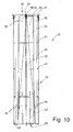
- bag filter 23 differs from the bag filter 22 in that the inner filter tube 54 tapers towards the suction end 34, that is conical in the longitudinal direction.
- the tapered Inner filter tube 54 only along a plane transverse to the longitudinal center plane 55 by the suction end 34 facing end of the inner filter tube 54 has an extending through the longitudinal central axis 24 edge 56 which is provided with a pocket 57 through which a support rod 58 is inserted.
- the holding rod 58 is supported with an outer end either on the suction end 34 facing end of a cylindrical support basket 59 for the outer filter tube 27 or the retaining collar 35 of the bag filter 23 at the suction end 34.
- the suction end 34 facing end of the tapered filter tube 54 is axially tensioned and fixed radially non-displaceable on the support basket 59 and / or on the retaining collar 35.
- the support basket 59 has a cylindrical grid-like support structure of longitudinal bars 60 and these connecting rings 61.
- the integrally made of plastic support basket 59 of the outer filter tube 27 is mounted.
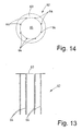
- the inner filter tube 54 is assigned a separate support basket 62.
- This support basket 62 is in the FIGS. 13 and 14 shown. Accordingly, the support basket 62 is composed of a ring 63 and on the circumference of the inner filter tube 54 distributed rods 64. The extending in the longitudinal direction of the inner filter tube 54 on the outside thereof rods 64 are connected in one piece with their ends on one side with the ring 63. The bars 64 are shorter than the inner filter tube 54, namely extend only over about a third of its length.
- the support basket 62 is associated with the suction end 34 opposite (lower) end of the inner filter tube 54 by the bars 64 abut the outside of the lower end portion of the inner filter tube 54 and the lower end of the inner filter tube 54 with the support basket 62, in particular the ring 63 is connected for example, by sewing, gluing, clamping or the like. Also, the support basket 62 is made of plastic.
- the support basket 62 is inserted centrally into the support basket 59 for the outer filter tube 27, wherein a relative to the bars 64 outwardly projecting portion of the ring 63 rests on a likewise formed by a ring 65 end of the support basket 59 for the outer filter tube 27, preferably sealing ,
- the ring 63 surrounds an inner opening 65 of the support basket 62, which corresponds approximately to the inner diameter of the inner filter tube 54.
- Around the opening 65 around the bars 64 are arranged distributed at uniform intervals. Through this opening 65, air to be filtered, which still contains solid particles, or dust can reach the interior of the inner filter tube 54.
- annular circumferential space 66 is present, which has the shape of a cylindrical annulus in the region of the support basket 62 and 34 adjacent to the suction end 34 of the above the support basket 62 tapered inner filter tube 54 to the suction end 34 with respect to the longitudinal center plane 55 steadily larger ,
- the air flow during operation of the bag filter 23 is in the Fig. 8 indicated by arrows. This corresponds in principle to the air flow, as has been described above in connection with the bag filter 22. Only the interior of the inner filter tube 54, through which the air or dust containing solids to be filtered is sucked in, continuously decreases towards the suction end 34 as a result of the tapered inner filter tube 54.
Landscapes
- Chemical & Material Sciences (AREA)
- Chemical Kinetics & Catalysis (AREA)
- Filtering Of Dispersed Particles In Gases (AREA)
- Filtering Materials (AREA)
Applications Claiming Priority (1)
| Application Number | Priority Date | Filing Date | Title |
|---|---|---|---|
| DE102007048554.0A DE102007048554B4 (de) | 2007-10-09 | 2007-10-09 | Schlauchfilter, Stützkorb für denselben und Schlauchfilteranlage |
Publications (2)
| Publication Number | Publication Date |
|---|---|
| EP2047896A2 true EP2047896A2 (fr) | 2009-04-15 |
| EP2047896A3 EP2047896A3 (fr) | 2009-06-03 |
Family
ID=40242585
Family Applications (1)
| Application Number | Title | Priority Date | Filing Date |
|---|---|---|---|
| EP08016934A Withdrawn EP2047896A3 (fr) | 2007-10-09 | 2008-09-26 | Filtre à manche, panier d'appui pour celui-ci et installation de filtre à manche |
Country Status (2)
| Country | Link |
|---|---|
| EP (1) | EP2047896A3 (fr) |
| DE (1) | DE102007048554B4 (fr) |
Cited By (2)
| Publication number | Priority date | Publication date | Assignee | Title |
|---|---|---|---|---|
| WO2012151186A1 (fr) * | 2011-05-02 | 2012-11-08 | Alstom Technology Ltd | Cage de filtre à manche |
| IT202000029492A1 (it) * | 2020-12-02 | 2022-06-02 | Progetto Energia S R L | Macchina per il filtraggio di miscele gassose, in particolare aria in ambienti industriali o simili |
Families Citing this family (1)
| Publication number | Priority date | Publication date | Assignee | Title |
|---|---|---|---|---|
| DE102011111527A1 (de) * | 2011-08-31 | 2013-02-28 | Mann + Hummel Gmbh | Filter und Verfahren zu seiner Herstellung |
Family Cites Families (5)
| Publication number | Priority date | Publication date | Assignee | Title |
|---|---|---|---|---|
| GB934838A (en) * | 1960-12-12 | 1963-08-21 | Bayer Ag | Keys from polyamides |
| GB1184070A (en) * | 1967-09-22 | 1970-03-11 | Sanko Seisakusho Kk | Improvements in or relating to Air Filters |
| DE4029994C2 (de) * | 1990-09-21 | 1994-01-05 | Herbert Huettlin | Filterpatrone zum Entstauben von Gasen |
| DE9306011U1 (de) * | 1993-04-21 | 1993-06-17 | Hüttlin, Herbert, 7853 Steinen | Filterpatrone zum Entstauben von Gasen |
| DE10124526C2 (de) * | 2001-05-19 | 2003-05-08 | Alfred Rachor | Filternde Entstauber mit Doppelfilterschlauchelementen und Druckluftabreinigung |
-
2007
- 2007-10-09 DE DE102007048554.0A patent/DE102007048554B4/de active Active
-
2008
- 2008-09-26 EP EP08016934A patent/EP2047896A3/fr not_active Withdrawn
Cited By (4)
| Publication number | Priority date | Publication date | Assignee | Title |
|---|---|---|---|---|
| WO2012151186A1 (fr) * | 2011-05-02 | 2012-11-08 | Alstom Technology Ltd | Cage de filtre à manche |
| US8956435B2 (en) | 2011-05-02 | 2015-02-17 | Alstom Technology Ltd | Baghouse filter cage |
| IT202000029492A1 (it) * | 2020-12-02 | 2022-06-02 | Progetto Energia S R L | Macchina per il filtraggio di miscele gassose, in particolare aria in ambienti industriali o simili |
| WO2022118205A1 (fr) * | 2020-12-02 | 2022-06-09 | Progetto Energia S.R.L. | Machine pour la filtration de mélanges gazeux, en particulier de l'air dans des environnements industriels ou similaires |
Also Published As
| Publication number | Publication date |
|---|---|
| DE102007048554A1 (de) | 2009-04-16 |
| EP2047896A3 (fr) | 2009-06-03 |
| DE102007048554B4 (de) | 2016-01-07 |
Similar Documents
| Publication | Publication Date | Title |
|---|---|---|
| DE112012000251B4 (de) | Staubbehälter für Staubsauger | |
| DE60109175T2 (de) | Filteranordnung | |
| DE112007001314T5 (de) | Separat öffnender Staubbehälter eines zyklonartigen Haushaltsstaubsaugers | |
| EP2862614B1 (fr) | Système de filtre équipé d'un élément de filtre | |
| EP2341999A2 (fr) | Élément filtrant pour épurer un flux d'air chargé de particules et dispositif de filtration équipé de cet élément | |
| DE202008008989U1 (de) | Staubsaugerfilterbeutel | |
| EP2979602A1 (fr) | Filtre a air a retrolavage | |
| CH647423A5 (de) | Zyklonabscheider mit saugwirkung. | |
| DE102007048554B4 (de) | Schlauchfilter, Stützkorb für denselben und Schlauchfilteranlage | |
| DE202011000339U1 (de) | Staubsaugerbeutel | |
| EP2359730B2 (fr) | Sac d'aspirateur doté d'un volet latéral | |
| DE2343971A1 (de) | Geraet zur fussbodenpflege | |
| EP0468200B1 (fr) | Sac de filtrage tubulaire | |
| DE3248891C2 (de) | Luftfilter | |
| EP2067427A2 (fr) | Sac anti-poussière pour aspirateurs | |
| EP2452603B1 (fr) | Sachet de filtre d'aspirateur plié | |
| EP3763431B1 (fr) | Appareil filtrant | |
| EP4272852A1 (fr) | Sac filtrant et module filtrant pour un filtre à disque rotatif et filtre à disque rotatif | |
| EP2108431A1 (fr) | Filtre à manche et son procédé de fabrication | |
| EP2851109B1 (fr) | Dispositif destiné à séparer des matières en suspension de l'air | |
| DE102011120688B4 (de) | Staubfilterbeutel mit einer Staubfängereinlage | |
| DE3937710C2 (de) | Vorrichtung für Industrie-Staubabsauggeräte zur Aufnahme des abgesaugten Staubes | |
| DE2227378C3 (de) | Filtersatz | |
| DE102014012944A1 (de) | Filtersystem mit Filterelement | |
| DE511984C (de) | Gasreiniger |
Legal Events
| Date | Code | Title | Description |
|---|---|---|---|
| PUAI | Public reference made under article 153(3) epc to a published international application that has entered the european phase |
Free format text: ORIGINAL CODE: 0009012 |
|
| AK | Designated contracting states |
Kind code of ref document: A2 Designated state(s): AT BE BG CH CY CZ DE DK EE ES FI FR GB GR HR HU IE IS IT LI LT LU LV MC MT NL NO PL PT RO SE SI SK TR |
|
| AX | Request for extension of the european patent |
Extension state: AL BA MK RS |
|
| PUAL | Search report despatched |
Free format text: ORIGINAL CODE: 0009013 |
|
| AK | Designated contracting states |
Kind code of ref document: A3 Designated state(s): AT BE BG CH CY CZ DE DK EE ES FI FR GB GR HR HU IE IS IT LI LT LU LV MC MT NL NO PL PT RO SE SI SK TR |
|
| AX | Request for extension of the european patent |
Extension state: AL BA MK RS |
|
| AKX | Designation fees paid | ||
| STAA | Information on the status of an ep patent application or granted ep patent |
Free format text: STATUS: THE APPLICATION IS DEEMED TO BE WITHDRAWN |
|
| 18D | Application deemed to be withdrawn |
Effective date: 20091204 |
|
| REG | Reference to a national code |
Ref country code: DE Ref legal event code: 8566 |