EP2047948A2 - Dispositif de ponçage de pièces usinées - Google Patents
Dispositif de ponçage de pièces usinées Download PDFInfo
- Publication number
- EP2047948A2 EP2047948A2 EP08016593A EP08016593A EP2047948A2 EP 2047948 A2 EP2047948 A2 EP 2047948A2 EP 08016593 A EP08016593 A EP 08016593A EP 08016593 A EP08016593 A EP 08016593A EP 2047948 A2 EP2047948 A2 EP 2047948A2
- Authority
- EP
- European Patent Office
- Prior art keywords
- workpiece
- grinding
- pressure
- actuator
- grinding element
- Prior art date
- Legal status (The legal status is an assumption and is not a legal conclusion. Google has not performed a legal analysis and makes no representation as to the accuracy of the status listed.)
- Withdrawn
Links
Images

Classifications
-
- B—PERFORMING OPERATIONS; TRANSPORTING
- B24—GRINDING; POLISHING
- B24B—MACHINES, DEVICES, OR PROCESSES FOR GRINDING OR POLISHING; DRESSING OR CONDITIONING OF ABRADING SURFACES; FEEDING OF GRINDING, POLISHING, OR LAPPING AGENTS
- B24B21/00—Machines or devices using grinding or polishing belts; Accessories therefor
- B24B21/04—Machines or devices using grinding or polishing belts; Accessories therefor for grinding plane surfaces
-
- B—PERFORMING OPERATIONS; TRANSPORTING
- B24—GRINDING; POLISHING
- B24B—MACHINES, DEVICES, OR PROCESSES FOR GRINDING OR POLISHING; DRESSING OR CONDITIONING OF ABRADING SURFACES; FEEDING OF GRINDING, POLISHING, OR LAPPING AGENTS
- B24B49/00—Measuring or gauging equipment for controlling the feed movement of the grinding tool or work; Arrangements of indicating or measuring equipment, e.g. for indicating the start of the grinding operation
- B24B49/16—Measuring or gauging equipment for controlling the feed movement of the grinding tool or work; Arrangements of indicating or measuring equipment, e.g. for indicating the start of the grinding operation taking regard of the load
-
- B—PERFORMING OPERATIONS; TRANSPORTING
- B24—GRINDING; POLISHING
- B24B—MACHINES, DEVICES, OR PROCESSES FOR GRINDING OR POLISHING; DRESSING OR CONDITIONING OF ABRADING SURFACES; FEEDING OF GRINDING, POLISHING, OR LAPPING AGENTS
- B24B7/00—Machines or devices designed for grinding plane surfaces on work, including polishing plane glass surfaces; Accessories therefor
- B24B7/10—Single-purpose machines or devices
- B24B7/12—Single-purpose machines or devices for grinding travelling elongated stock, e.g. strip-shaped work
-
- B—PERFORMING OPERATIONS; TRANSPORTING
- B24—GRINDING; POLISHING
- B24B—MACHINES, DEVICES, OR PROCESSES FOR GRINDING OR POLISHING; DRESSING OR CONDITIONING OF ABRADING SURFACES; FEEDING OF GRINDING, POLISHING, OR LAPPING AGENTS
- B24B9/00—Machines or devices designed for grinding edges or bevels on work or for removing burrs; Accessories therefor
- B24B9/002—Machines or devices designed for grinding edges or bevels on work or for removing burrs; Accessories therefor for travelling workpieces
Definitions
- the invention relates to a device for grinding workpieces according to the preamble of claim 1.
- Grinding devices incorporating e.g. Workpieces made of steel are machined on their underside, known in the art abrasive elements in the form of occupied with abrasive cloth or sandpaper frame-fixed sanding rollers or belt grinding units.
- the latter have an endless abrasive belt, which is guided over a workpiece-contacting frame-fixed contact roller and two or more guide rollers.
- the workpieces travel over driven rubberized support rollers which, viewed in the conveying direction of the workpiece, are arranged upstream and downstream of the grinding rollers or abrasive belts.
- pressure-loaded pressure rollers are arranged which press on the workpiece, while this along the path defined by the idlers and pressure rollers conveying path on the grinding roller, or the Contact roller is moved.
- the grinding elements are dependent on the desired degradation capacity, ie. the amount of material to be removed per unit time from the workpiece, adjusted in such a way that the contact lines of the loop elements with the workpiece are correspondingly higher than the contact lines between the workpiece and the support rollers.
- the invention provides the advantage that workpieces of substantially identical shape, regardless of e.g. a plane-parallelism tolerance brought about by a thermal separation process can be passed through the device immediately one after the other, without this having to be newly set to the respective degree of deformation of a workpiece each time.
- the device according to the invention makes it possible to grind the main surfaces of a substantially planar workpiece, irrespective of the respective tolerance, in order to clamp the workpiece, e.g. completely rid of burrs in the area of its underside.
- Another advantage of the device according to the invention is that it does not damage even the otherwise plane-parallel workpieces, which are greatly deformed by the previous machining operation, the preferably rubber-elastic lateral surface of the grinding roller or contact roller.
- a device for grinding a flat workpiece which along along at least partially driven support rollers and pressure rollers defined transport path is required, extending in the transport path into a circumferential grinding element, which contacts the workpiece on its way along the transport path circumferentially.
- the device according to the invention further comprises pressure means, which act on the rotating grinding element in the direction of the workpiece with a resilient pressure force, such that the rotating grinding element of the contour of the flat workpiece is made flexible following the workpiece.
- the pressure means may also have linear guides, they preferably have first and second swiveling levers or rocker arms rotatably receiving the revolving grinding element and an actuator acting on them, in particular a pneumatic cylinder.
- an electronic control device which regulates the pressing force with which the actuator acts on the revolving grinding element and / or the position thereof.
- the device according to the invention preferably has a workpiece width detection device connected to the electronic control device, which is arranged upstream of the revolving grinding element in the workpiece conveying direction and from which the electronic control device receives signals which correspond to the currently measured width of the workpiece in the region of the workpiece width detection device.
- the electronic control device changes the force of the actuator in response to the signals of the workpiece width detection means in such a way that the ratio of pressure force and workpiece width corresponds to a substantially constant preset value, for example, before the processing of a particular workpiece type can be entered by the operator.
- This has the advantage that the contact pressure - and thus the degradation - not on the current width of a Workpiece in the region of the rotating abrasive, whereby the load of the abrasive for narrow workpieces compared to grinding devices, where the pressure is constant, reduced, and the specific material removal is made uniform.
- the electronic control device controls the actuator in response to signals of the workpiece width detection means in such a way that the rotating grinding element is moved from a position outside the transport path into this when the workpiece leading edge is in the region of the peripheral grinding element. In a corresponding manner, the rotating grinding element is moved out of the transport path after the workpiece trailing edge has passed the rotating grinding element.
- the support rollers and / or the pressure rollers are driven, for example via a revolving chain with a substantially constant rotational speed.
- the electronic control device changes the pressing force with which the actuator acts on the revolving grinding element in a controlled manner as a function of the workpiece width detected by the workpiece width detecting device.
- a rotation angle sensor is preferably arranged on one of the support rollers and / or pressure rollers, which detects the angular position of the roller, which together with the associated, determined by the workpiece width detection means instantaneous workpiece width. is cached in the electronic control device.
- the abutment pressure of the grinding member corresponding to the associated workpiece width value is correspondingly reduced or increased by the electronic control means.
- the rotating grinding element in the direction of the workpiece movable counter-pressure roller assigned, which is arranged on the opposite side of the transport path, and which is hired by further pressure means with a resilient counterforce to the workpiece
- the further pressure means preferably have a further actuator, in particular a pneumatic cylinder, whose pressure force is changed by the electronic control device in response to the resilient pressure force with which the rotating grinding element is placed against the workpiece to prevent the workpiece in the direction of Dodge roller out dodges.
- the adjustment of the contact pressure of the further actuator is preferably carried out during the entire implementation process of the workpiece by the device automatically.
- the grinding element is formed by a grinding roller arranged on the underside of the transport path.
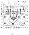
- the grinding device comprises a machine stand consisting of two cheeks or side panels 1, four trusses 2 and two trusses 3.
- a support frame 5 is added, which consists of two inner cheeks or side panels 5a and two other trusses 6.
- the trusses 6 are preferably provided for receiving the threaded spindle 4 with an internal thread.
- the threaded spindles 4 are driven by a gear motor 7, a chain 8 and sprockets 9 to the Adjust workpiece thickness.
- the support frame 5 is preferably loaded by springs 10 rubberized pressure rollers 11, which are each mounted on rocking levers 12, which can be pivoted about an associated pin 13.
- a counter-pressure roller 14 is mounted on the support frame 5, which is rotatably mounted on a rocker arm 15 arranged on both sides, which is preferably also received about a pin 16 pivotally mounted on the inner cheeks 5a.
- the rocker arms 15 are acted upon by an actuator in the form of an air cylinder 16a attached to both sides of the working width with a resilient pressure force to the counter-pressure roller 14 to the workpiece.
- the pressure rollers 11 are opposite to the two cheeks 1 preferably rubberized support rollers 18 are rotatably received, which are driven by a motor, preferably a geared motor 19, sprockets 21 and a chain 22 guided over all sprockets 21 together.
- the support rollers 18 define together with the pressure rollers 11 a transport path 100 for the incoming workpiece 33rd
- a grinding element in the form of a grinding roller 23 or a contact roller, not shown, over which an endless abrasive belt is guided, is by an electric motor not shown in detail, for. powered by V-belt pulleys and V-belts.
- the grinding roller 23 is covered with a rubber coating 24, on the circumferential surface of which the abrasive 25 - e.g. Sandpaper or abrasive cloth - is fixed and stretched in a known manner.
- the abrasive 25 - e.g. Sandpaper or abrasive cloth - is fixed and stretched in a known manner.
- the grinding roller 23 is preferably mounted in two bearing bushes 26, each resting on an associated guide roller 27.
- Each guide roller 27 is preferably mounted on two rocker arms 28, which are connected to one another via a connecting element 29 and are pivotable by means of bolts 30.
- the bolts 30 are supported as in Fig. 2 shown, over two angles 30a on the cheeks 1 of the machine stand from. As a result, the entire unit consisting of the two oscillating levers or pivoting levers 28 and the connecting element 29 is pivotally mounted on the bolt 30.
- This unit which is mounted on the left and right of the working width, is supported in each case on an actuator, which is preferably designed as a pneumatic cylinder 31.
- the unit consisting of the two rocker arms 28, the connecting element 29, the bolt 30, the angle 30a and the pneumatic cylinder 31 is hereinafter also referred to as pressure means for the sake of simplicity.
- a workpiece width detecting device is mounted in the form of a light grid 32, which is e.g. may consist of a plurality of light sources and associated light sensors not shown in detail, which detect the instantaneous width of the workpiece 33 when passing through the transport path 100 as well as the entry of the leading and trailing edges of the workpiece 33 in the transport path 100.
- the running in the direction indicated by the arrow 102 conveying direction workpiece 33 passes over the light grid 32, which detects the leading edge of the workpiece 33, and thereafter scans the width of the workpiece 33 until the trailing edge of the workpiece 33 has passed the light grid 32.
- An electronic control device which communicates with the light grid 32 as well as a solenoid valve (not shown) associated with each pneumatic cylinder 31, controls the solenoid valves in such a manner that the grinding roller 23 is set against the underside of the workpiece when the leading edge of the workpiece 33 is perpendicular to the grinding roller 23.
- the pneumatic cylinder 31 - relieved by the electronic control device - relieved so that the grinding roller 23 moves back due to its own weight in the starting position in which the peripheral surface of the grinding roller 23 outside of Transport path 102 is located.
- the support roller 14 is pressed according to the grinding pressure by the further pneumatic cylinder 16a on the workpiece 33 to produce a resilient counterforce, which counteracts the pressure force generated by the pneumatic cylinder 31.
- the pressure rollers 11 are also loaded with a substantially constant force of the springs 10, whereas the support rollers or support rollers 18 are mounted fixed to the frame in the machine stand.
- the respectively desired workpiece thickness is set before machining a workpiece series via the motor 7, the sprockets 9, the chain 18 and the threaded spindles 4 and threaded nuts 6.
Landscapes
- Engineering & Computer Science (AREA)
- Mechanical Engineering (AREA)
- Constituent Portions Of Griding Lathes, Driving, Sensing And Control (AREA)
- Grinding Of Cylindrical And Plane Surfaces (AREA)
- Finish Polishing, Edge Sharpening, And Grinding By Specific Grinding Devices (AREA)
Applications Claiming Priority (1)
| Application Number | Priority Date | Filing Date | Title |
|---|---|---|---|
| DE102007048544A DE102007048544A1 (de) | 2007-10-09 | 2007-10-09 | Vorrichtung zum Schleifen von Werkstücken |
Publications (2)
| Publication Number | Publication Date |
|---|---|
| EP2047948A2 true EP2047948A2 (fr) | 2009-04-15 |
| EP2047948A3 EP2047948A3 (fr) | 2010-06-09 |
Family
ID=40227518
Family Applications (1)
| Application Number | Title | Priority Date | Filing Date |
|---|---|---|---|
| EP08016593A Withdrawn EP2047948A3 (fr) | 2007-10-09 | 2008-09-20 | Dispositif de ponçage de pièces usinées |
Country Status (3)
| Country | Link |
|---|---|
| US (1) | US20090093197A1 (fr) |
| EP (1) | EP2047948A3 (fr) |
| DE (1) | DE102007048544A1 (fr) |
Cited By (1)
| Publication number | Priority date | Publication date | Assignee | Title |
|---|---|---|---|---|
| WO2022184882A3 (fr) * | 2021-03-05 | 2022-11-03 | Karl Heesemann Maschinenfabrik Gmbh & Co. Kg | Unité d'ébavurage et d'arrondi de bords dans une machine de meulage de surface |
Families Citing this family (7)
| Publication number | Priority date | Publication date | Assignee | Title |
|---|---|---|---|---|
| AT508789B1 (de) * | 2009-10-13 | 2013-01-15 | Wintersteiger Ag | Bearbeitungsvorrichtung für skier |
| JP6251144B2 (ja) * | 2014-09-12 | 2017-12-20 | 株式会社東芝 | 表面処理装置、および表面処理方法 |
| PL3085491T3 (pl) | 2015-04-24 | 2017-09-29 | Arku Maschinenbau Gmbh | Urządzenie do szlifowania i usuwania zadziorów z płaskiego przedmiotu obrabianego |
| CN106217171A (zh) * | 2016-08-31 | 2016-12-14 | 安吉万昌家具有限公司 | 桌椅板倒角加工设备及其加工方法 |
| DE102016013408A1 (de) * | 2016-11-04 | 2018-05-30 | Michael Weinig Ag | Maschine und Verfahren zur Bearbeitung von Werkstücken aus Holz, Kunststoff und dgl. |
| CN108927714B (zh) * | 2018-08-07 | 2020-11-20 | 望江县南山刷业有限公司 | 一种用于刷子加工的打磨装置 |
| CN118682590A (zh) * | 2024-08-28 | 2024-09-24 | 中国科学院长春光学精密机械与物理研究所 | 一种逆重力的反射镜孔位研磨装置及其应用 |
Family Cites Families (15)
| Publication number | Priority date | Publication date | Assignee | Title |
|---|---|---|---|---|
| DE1177973B (de) * | 1960-10-03 | 1964-09-10 | Merit Products Inc | Vorrichtung an Schleifmaschinen zum Schutze der hinteren Kante plattenfoermiger Werkstuecke |
| US3277609A (en) * | 1964-02-07 | 1966-10-11 | Tomohiro Horie | Method and apparatus for surface grinding |
| DE3045234A1 (de) * | 1980-12-01 | 1982-07-01 | Wesero Maschinenbau GmbH, 4322 Sprockhövel | Schleifmaschine zum schleifen von platten oder baendern |
| US4941290A (en) * | 1989-01-23 | 1990-07-17 | Holyoke Robert H | Apparatus for removing photographic images from a film member |
| DE4108147C1 (en) * | 1991-03-13 | 1992-08-13 | Paul Ernst Maschinenfabrik Gmbh, 6925 Eschelbronn, De | Grinding machine for deburring and finishing flat work - has switches operating electronic circuit controlling proportional valve setting pressure in lifting hose |
| US5501629A (en) * | 1992-09-10 | 1996-03-26 | Fujitsu Limited | Buffing apparatus suitable to buff thin plate work and controlling method for the apparatus |
| CA2169997A1 (fr) * | 1995-03-17 | 1996-09-18 | Gregory Zang | Machine d'abrasion multidirectionnelle |
| US5759089A (en) * | 1996-01-16 | 1998-06-02 | Mccoy; Thomas Edward | Apparatus for in-line surface finishing of cylindrical tubing such as stainless steel tubing with supporting mandrel and method |
| JPH11170723A (ja) * | 1997-12-12 | 1999-06-29 | Fuji Photo Film Co Ltd | 平版印刷用支持体の表面処理方法及び装置 |
| DE19915909C2 (de) * | 1998-12-11 | 2003-05-28 | Steinemann Technology Ag St Ga | Verfahren zur Steuerung des Schleifprozesses sowie Rechnersteuerung für Breitschleifmaschine |
| US6296029B1 (en) * | 1999-07-21 | 2001-10-02 | Timesavers, Inc. | Centering sectional shoe assembly |
| US6306015B1 (en) * | 2000-01-03 | 2001-10-23 | Machine And Wheels, Inc. | Method for grinding rigid materials |
| US6899606B2 (en) * | 2003-03-06 | 2005-05-31 | Juei-Seng Liao | Rotary grinding machine |
| US6877502B2 (en) * | 2003-06-06 | 2005-04-12 | Sean Register | Multi-blade concrete cutting saw |
| US7014544B2 (en) * | 2004-06-23 | 2006-03-21 | Wmh Tool Group Hong Kong Limited | Reciprocating and deflecting swing device for the roller of a cylindrical emery-polishing machine |
-
2007
- 2007-10-09 DE DE102007048544A patent/DE102007048544A1/de not_active Withdrawn
-
2008
- 2008-09-20 EP EP08016593A patent/EP2047948A3/fr not_active Withdrawn
- 2008-10-07 US US12/246,897 patent/US20090093197A1/en not_active Abandoned
Cited By (2)
| Publication number | Priority date | Publication date | Assignee | Title |
|---|---|---|---|---|
| WO2022184882A3 (fr) * | 2021-03-05 | 2022-11-03 | Karl Heesemann Maschinenfabrik Gmbh & Co. Kg | Unité d'ébavurage et d'arrondi de bords dans une machine de meulage de surface |
| US12667928B2 (en) | 2021-03-05 | 2026-06-30 | Karl Heesemann Maschinenfabrik Gmbh & Co. Kg | Unit for deburring and rounding edges in a surface grinding machine |
Also Published As
| Publication number | Publication date |
|---|---|
| US20090093197A1 (en) | 2009-04-09 |
| DE102007048544A1 (de) | 2009-04-16 |
| EP2047948A3 (fr) | 2010-06-09 |
Similar Documents
| Publication | Publication Date | Title |
|---|---|---|
| DE102007048544A1 (de) | Vorrichtung zum Schleifen von Werkstücken | |
| EP1112811B1 (fr) | Machine à meuler à bande pour le meulage de tubes | |
| DE1729773C3 (de) | Maschine zum Zerschneiden von mit Kautschuk beschichtetem Gewebe | |
| DE9116540U1 (de) | Vorrichtung zum Schleifen von Kurbelzapfenlagern an Kurbelwellen | |
| DE2714973C2 (de) | Vorrichtung zum Vorschieben von Rohbrettern zu einer Kantenbesäumsäge | |
| DE19510649A1 (de) | Transportvorrichtung | |
| DE2417568A1 (de) | Maschine zum schleifen der umfangskanten von flachglas und glasaehnlichem material | |
| DE2523225C2 (de) | Schleifmaschine, insbesondere zum Schleifen von Holzteilen | |
| DE3029591C2 (fr) | ||
| EP0708050B1 (fr) | Dispositif pivotant de transport de câble | |
| WO2013104706A1 (fr) | Installation de traitement du bois, et procédé permettant de faire fonctionner ladite installation de traitement du bois | |
| EP2982485A1 (fr) | Dispositif et procede d'execution de coupes transversales sur des pieces en bois | |
| CH616619A5 (fr) | ||
| DE3841916A1 (de) | Verfahren zum steuern der andrueckkraft eines werkzeugs sowie werkzeugmaschine zu seiner durchfuehrung | |
| EP0085908B1 (fr) | Machine à palissonner | |
| DE3873906T2 (de) | Drahtfuehrung bei einer drahterosionsbearbeitungsvorrichtung. | |
| DE2335575B2 (fr) | ||
| DE4108147C1 (en) | Grinding machine for deburring and finishing flat work - has switches operating electronic circuit controlling proportional valve setting pressure in lifting hose | |
| DE3010733A1 (de) | Zwangsfuehrungseinrichtung fuer ein zu zerschneidendes produkt in der nachbarschft der messerscheibe einer schneidmaschine | |
| DE10040580A1 (de) | Vorrichtung zum Führen von Signaturen, insbesondere im Bereich eines Auslauf-Zwickels einer Schneidzylinderanordnung in einem Falzapparat einer Rotationsdruckmaschine | |
| DE2947039C2 (fr) | ||
| DE19948704C1 (de) | Vorrichtung zum Drehen eines Papierstapels | |
| EP1862274B1 (fr) | Dispositif de traitement de produits imprimés | |
| DE10129007C1 (de) | Vorrichtung zum unterschuppten Zuführen von Bogen | |
| DE2952012C2 (de) | Andrückvorrichtung für Kantenumleimer |
Legal Events
| Date | Code | Title | Description |
|---|---|---|---|
| PUAI | Public reference made under article 153(3) epc to a published international application that has entered the european phase |
Free format text: ORIGINAL CODE: 0009012 |
|
| AK | Designated contracting states |
Kind code of ref document: A2 Designated state(s): AT BE BG CH CY CZ DE DK EE ES FI FR GB GR HR HU IE IS IT LI LT LU LV MC MT NL NO PL PT RO SE SI SK TR |
|
| AX | Request for extension of the european patent |
Extension state: AL BA MK RS |
|
| PUAL | Search report despatched |
Free format text: ORIGINAL CODE: 0009013 |
|
| AK | Designated contracting states |
Kind code of ref document: A3 Designated state(s): AT BE BG CH CY CZ DE DK EE ES FI FR GB GR HR HU IE IS IT LI LT LU LV MC MT NL NO PL PT RO SE SI SK TR |
|
| AX | Request for extension of the european patent |
Extension state: AL BA MK RS |
|
| RIC1 | Information provided on ipc code assigned before grant |
Ipc: B24B 49/16 20060101ALI20100504BHEP Ipc: B24B 21/04 20060101ALI20100504BHEP Ipc: B24B 9/00 20060101ALI20100504BHEP Ipc: B24B 7/12 20060101AFI20100504BHEP |
|
| AKX | Designation fees paid |
Designated state(s): AT BE BG CH CY CZ DE DK EE ES FI FR GB GR HR HU IE IS IT LI LT LU LV MC MT NL NO PL PT RO SE SI SK TR |
|
| STAA | Information on the status of an ep patent application or granted ep patent |
Free format text: STATUS: THE APPLICATION IS DEEMED TO BE WITHDRAWN |
|
| 18D | Application deemed to be withdrawn |
Effective date: 20101210 |