EP2048014A2 - Agencement de profilé et procédé de fabrication d'un agencement de profilé - Google Patents
Agencement de profilé et procédé de fabrication d'un agencement de profilé Download PDFInfo
- Publication number
- EP2048014A2 EP2048014A2 EP08016345A EP08016345A EP2048014A2 EP 2048014 A2 EP2048014 A2 EP 2048014A2 EP 08016345 A EP08016345 A EP 08016345A EP 08016345 A EP08016345 A EP 08016345A EP 2048014 A2 EP2048014 A2 EP 2048014A2
- Authority
- EP
- European Patent Office
- Prior art keywords
- profile
- strip profile
- switching strip
- switching
- carrier part
- Prior art date
- Legal status (The legal status is an assumption and is not a legal conclusion. Google has not performed a legal analysis and makes no representation as to the accuracy of the status listed.)
- Granted
Links
- 238000004519 manufacturing process Methods 0.000 title claims abstract description 9
- 238000002347 injection Methods 0.000 claims abstract description 43
- 239000007924 injection Substances 0.000 claims abstract description 43
- 238000000034 method Methods 0.000 claims abstract description 8
- 239000004020 conductor Substances 0.000 claims description 70
- 230000005684 electric field Effects 0.000 claims description 25
- 238000005507 spraying Methods 0.000 claims description 14
- 238000001746 injection moulding Methods 0.000 claims description 11
- 230000009969 flowable effect Effects 0.000 claims description 4
- 239000003990 capacitor Substances 0.000 claims description 3
- 238000007789 sealing Methods 0.000 claims description 3
- 239000000463 material Substances 0.000 description 19
- 238000011161 development Methods 0.000 description 11
- 238000001514 detection method Methods 0.000 description 10
- 239000002184 metal Substances 0.000 description 5
- 238000005520 cutting process Methods 0.000 description 4
- 238000013461 design Methods 0.000 description 3
- 238000001125 extrusion Methods 0.000 description 3
- 238000000465 moulding Methods 0.000 description 3
- 238000005238 degreasing Methods 0.000 description 2
- 238000011156 evaluation Methods 0.000 description 2
- 238000007711 solidification Methods 0.000 description 2
- 230000008023 solidification Effects 0.000 description 2
- 239000012790 adhesive layer Substances 0.000 description 1
- 238000005452 bending Methods 0.000 description 1
- 230000015572 biosynthetic process Effects 0.000 description 1
- 238000004891 communication Methods 0.000 description 1
- 239000012141 concentrate Substances 0.000 description 1
- 229920001940 conductive polymer Polymers 0.000 description 1
- 238000003780 insertion Methods 0.000 description 1
- 230000037431 insertion Effects 0.000 description 1
- 239000007788 liquid Substances 0.000 description 1
- 229920000642 polymer Polymers 0.000 description 1
- 229920000098 polyolefin Polymers 0.000 description 1
- 238000002360 preparation method Methods 0.000 description 1
- 239000007921 spray Substances 0.000 description 1
- 230000006641 stabilisation Effects 0.000 description 1
- 238000011105 stabilization Methods 0.000 description 1
- 238000012360 testing method Methods 0.000 description 1
Images



Classifications
-
- H—ELECTRICITY
- H01—ELECTRIC ELEMENTS
- H01R—ELECTRICALLY-CONDUCTIVE CONNECTIONS; STRUCTURAL ASSOCIATIONS OF A PLURALITY OF MUTUALLY-INSULATED ELECTRICAL CONNECTING ELEMENTS; COUPLING DEVICES; CURRENT COLLECTORS
- H01R43/00—Apparatus or processes specially adapted for manufacturing, assembling, maintaining, or repairing of line connectors or current collectors or for joining electric conductors
-
- B—PERFORMING OPERATIONS; TRANSPORTING
- B29—WORKING OF PLASTICS; WORKING OF SUBSTANCES IN A PLASTIC STATE IN GENERAL
- B29C—SHAPING OR JOINING OF PLASTICS; SHAPING OF MATERIAL IN A PLASTIC STATE, NOT OTHERWISE PROVIDED FOR; AFTER-TREATMENT OF THE SHAPED PRODUCTS, e.g. REPAIRING
- B29C45/00—Injection moulding, i.e. forcing the required volume of moulding material through a nozzle into a closed mould; Apparatus therefor
- B29C45/14—Injection moulding, i.e. forcing the required volume of moulding material through a nozzle into a closed mould; Apparatus therefor incorporating preformed parts or layers, e.g. injection moulding around inserts or for coating articles
- B29C45/14336—Coating a portion of the article, e.g. the edge of the article
-
- B—PERFORMING OPERATIONS; TRANSPORTING
- B60—VEHICLES IN GENERAL
- B60J—WINDOWS, WINDSCREENS, NON-FIXED ROOFS, DOORS, OR SIMILAR DEVICES FOR VEHICLES; REMOVABLE EXTERNAL PROTECTIVE COVERINGS SPECIALLY ADAPTED FOR VEHICLES
- B60J10/00—Sealing arrangements
- B60J10/30—Sealing arrangements characterised by the fastening means
-
- B—PERFORMING OPERATIONS; TRANSPORTING
- B60—VEHICLES IN GENERAL
- B60J—WINDOWS, WINDSCREENS, NON-FIXED ROOFS, DOORS, OR SIMILAR DEVICES FOR VEHICLES; REMOVABLE EXTERNAL PROTECTIVE COVERINGS SPECIALLY ADAPTED FOR VEHICLES
- B60J10/00—Sealing arrangements
- B60J10/80—Sealing arrangements specially adapted for opening panels, e.g. doors
-
- E—FIXED CONSTRUCTIONS
- E05—LOCKS; KEYS; WINDOW OR DOOR FITTINGS; SAFES
- E05F—DEVICES FOR MOVING WINGS INTO OPEN OR CLOSED POSITION; CHECKS FOR WINGS; WING FITTINGS NOT OTHERWISE PROVIDED FOR, CONCERNED WITH THE FUNCTIONING OF THE WING
- E05F15/00—Power-operated mechanisms for wings
-
- B—PERFORMING OPERATIONS; TRANSPORTING
- B29—WORKING OF PLASTICS; WORKING OF SUBSTANCES IN A PLASTIC STATE IN GENERAL
- B29C—SHAPING OR JOINING OF PLASTICS; SHAPING OF MATERIAL IN A PLASTIC STATE, NOT OTHERWISE PROVIDED FOR; AFTER-TREATMENT OF THE SHAPED PRODUCTS, e.g. REPAIRING
- B29C45/00—Injection moulding, i.e. forcing the required volume of moulding material through a nozzle into a closed mould; Apparatus therefor
- B29C45/14—Injection moulding, i.e. forcing the required volume of moulding material through a nozzle into a closed mould; Apparatus therefor incorporating preformed parts or layers, e.g. injection moulding around inserts or for coating articles
- B29C45/14065—Positioning or centering articles in the mould
- B29C2045/14155—Positioning or centering articles in the mould using vacuum or suction
-
- B—PERFORMING OPERATIONS; TRANSPORTING
- B29—WORKING OF PLASTICS; WORKING OF SUBSTANCES IN A PLASTIC STATE IN GENERAL
- B29C—SHAPING OR JOINING OF PLASTICS; SHAPING OF MATERIAL IN A PLASTIC STATE, NOT OTHERWISE PROVIDED FOR; AFTER-TREATMENT OF THE SHAPED PRODUCTS, e.g. REPAIRING
- B29C45/00—Injection moulding, i.e. forcing the required volume of moulding material through a nozzle into a closed mould; Apparatus therefor
- B29C45/14—Injection moulding, i.e. forcing the required volume of moulding material through a nozzle into a closed mould; Apparatus therefor incorporating preformed parts or layers, e.g. injection moulding around inserts or for coating articles
- B29C45/14065—Positioning or centering articles in the mould
-
- B—PERFORMING OPERATIONS; TRANSPORTING
- B29—WORKING OF PLASTICS; WORKING OF SUBSTANCES IN A PLASTIC STATE IN GENERAL
- B29C—SHAPING OR JOINING OF PLASTICS; SHAPING OF MATERIAL IN A PLASTIC STATE, NOT OTHERWISE PROVIDED FOR; AFTER-TREATMENT OF THE SHAPED PRODUCTS, e.g. REPAIRING
- B29C45/00—Injection moulding, i.e. forcing the required volume of moulding material through a nozzle into a closed mould; Apparatus therefor
- B29C45/14—Injection moulding, i.e. forcing the required volume of moulding material through a nozzle into a closed mould; Apparatus therefor incorporating preformed parts or layers, e.g. injection moulding around inserts or for coating articles
- B29C45/14311—Injection moulding, i.e. forcing the required volume of moulding material through a nozzle into a closed mould; Apparatus therefor incorporating preformed parts or layers, e.g. injection moulding around inserts or for coating articles using means for bonding the coating to the articles
-
- B—PERFORMING OPERATIONS; TRANSPORTING
- B29—WORKING OF PLASTICS; WORKING OF SUBSTANCES IN A PLASTIC STATE IN GENERAL
- B29C—SHAPING OR JOINING OF PLASTICS; SHAPING OF MATERIAL IN A PLASTIC STATE, NOT OTHERWISE PROVIDED FOR; AFTER-TREATMENT OF THE SHAPED PRODUCTS, e.g. REPAIRING
- B29C45/00—Injection moulding, i.e. forcing the required volume of moulding material through a nozzle into a closed mould; Apparatus therefor
- B29C45/14—Injection moulding, i.e. forcing the required volume of moulding material through a nozzle into a closed mould; Apparatus therefor incorporating preformed parts or layers, e.g. injection moulding around inserts or for coating articles
- B29C45/14639—Injection moulding, i.e. forcing the required volume of moulding material through a nozzle into a closed mould; Apparatus therefor incorporating preformed parts or layers, e.g. injection moulding around inserts or for coating articles for obtaining an insulating effect, e.g. for electrical components
-
- B—PERFORMING OPERATIONS; TRANSPORTING
- B29—WORKING OF PLASTICS; WORKING OF SUBSTANCES IN A PLASTIC STATE IN GENERAL
- B29L—INDEXING SCHEME ASSOCIATED WITH SUBCLASS B29C, RELATING TO PARTICULAR ARTICLES
- B29L2031/00—Other particular articles
- B29L2031/001—Profiled members, e.g. beams, sections
- B29L2031/003—Profiled members, e.g. beams, sections having a profiled transverse cross-section
-
- B—PERFORMING OPERATIONS; TRANSPORTING
- B29—WORKING OF PLASTICS; WORKING OF SUBSTANCES IN A PLASTIC STATE IN GENERAL
- B29L—INDEXING SCHEME ASSOCIATED WITH SUBCLASS B29C, RELATING TO PARTICULAR ARTICLES
- B29L2031/00—Other particular articles
- B29L2031/34—Electrical apparatus, e.g. sparking plugs or parts thereof
- B29L2031/3443—Switches
-
- Y—GENERAL TAGGING OF NEW TECHNOLOGICAL DEVELOPMENTS; GENERAL TAGGING OF CROSS-SECTIONAL TECHNOLOGIES SPANNING OVER SEVERAL SECTIONS OF THE IPC; TECHNICAL SUBJECTS COVERED BY FORMER USPC CROSS-REFERENCE ART COLLECTIONS [XRACs] AND DIGESTS
- Y10—TECHNICAL SUBJECTS COVERED BY FORMER USPC
- Y10T—TECHNICAL SUBJECTS COVERED BY FORMER US CLASSIFICATION
- Y10T428/00—Stock material or miscellaneous articles
- Y10T428/24—Structurally defined web or sheet [e.g., overall dimension, etc.]
- Y10T428/24479—Structurally defined web or sheet [e.g., overall dimension, etc.] including variation in thickness
Definitions
- the invention relates to a profile arrangement with a carrier part designed as a plastic injection-molded part and an at least partially elastically resilient switching strip profile, wherein the switching strip profile has a holding portion which is connected to the carrier part.
- the invention also relates to a method for producing a profile arrangement with a carrier part designed as a plastic injection-molded part and an at least partially elastically resilient switching strip profile.
- the invention is intended to provide a profile arrangement which can be produced with little expenditure of time and can be manufactured reliably and a corresponding method for producing a profile arrangement.
- this is provided by a profile arrangement with a carrier part designed as a plastic injection molded part and an at least partially elastically resilient switching strip profile, wherein the switching strip profile has a holding portion which is connected to the carrier part, wherein the holding portion of the switching strip profile by molding a carrier portion at least partially cohesively with the carrier part connected is.
- the holding portion of the switching strip profile is connected by injection molding with the support member, a secure attachment, wherein the cohesive connection between the support member and holding portion of the switching strip profile during the injection molding of the support member is formed.
- the connection of the switching strip profile and the carrier part is thereby effected in a production step which is required in any case for producing the carrier part. This facilitates the production, since the support member itself no preparatory work, such as degreasing or the like, such as when sticking the switching strip profile, are required.
- very tight manufacturing tolerances can be achieved are, since the contact strip profile is always arranged in one and the same position relative to the support member and specifically no positioning errors when placing the contact strip profile can arise on the support member.
- the carrier portion has at least one rib and the holding portion of the switching strip profile is integrally connected to a narrow side of the rib.
- Ribs on the support portion provide on the one hand for a stabilization of the support member.
- the holding portion of the switching strip profile on the other hand is connected to a narrow side of the rib, it can be achieved that less pressure is exerted on the switching strip profile during the injection process than would be the case with full contact surface of the holding portion of the switching strip profile. In this way it can be ensured that the switching strip profile only slightly deformed during injection molding of the support section and also in the final state has an optimal cross section for the performance of the safety edge function.
- the support member has a plurality of ribs, which protrude freely with its respective end portion of a base portion of the support member, wherein the holding portion of the contact strip profile rests on the end portions of the ribs and is connected cohesively thereto.
- the holding section may have a strip or rib extending away from the switching strip profile, which strip is surrounded on both sides by the plastic material of the carrier part after the injection molding of the carrier part.
- the holding portion of the switching strip profile is provided with projections, ribs and / or steps.
- the holding portion of the switching strip profile is provided with at least one undercut and positively connected in the region of the undercut with the carrier part.
- the holding portion has a dovetail-shaped in cross-section, projecting bar, which is surrounded by the plastic material of the carrier part during injection molding of the carrier part. This creates a positive connection in addition to the material connection.
- dovetail-shaped grooves can be provided on the holding section, which grooves are filled by the plastic material of the carrier part.
- the support member is formed as an elongated strip and provided with fastening means for attachment to a vehicle body.
- a switching strip profile can be produced together with the carrier part as directly mountable on the motor vehicle element and for fixing the support part, for example, expansion rivets or the like can be provided.
- the switching strip profile extends along its longitudinal direction and / or along its transverse direction.
- the switching strip profile can be adapted to curvatures of door or flap openings on the motor vehicle. It is essential that the switching strip profile is fixed during the molding of the support member in its curved position. Even with spatially curved curves of a switching strip profile can be ensured that the switching strip profile is always connected in the predetermined position with the support member. As a result, extremely precisely fitting parts can be produced with little effort.
- the holding part of the switching strip profile is at least partially made of electrically conductive material.
- the holding part of the switching strip profile can be used as a shield electrode in capacitive detection of obstacles.
- the carrier part consists at least in sections of electrically conductive material.
- the support member for shielding an electric field, which emanates for the capacitive detection of obstacles during operation of the contact strip profile. Since the support member is for mounting on a vehicle body, an electric field for detecting obstacles must extend away from the body. In the case of sheet metal bodies, this is generally not a problem, but if, for example, plastic doors or plastic flaps are used, a carrier part made of electrically conductive material makes the shielding of such an electric field much easier.
- the switching strip profile has at least two conductors extending parallel to the longitudinal direction of the switching strip profile and spaced from one another, wherein a first conductor is designed as a capacitor electrode for generating an electric field and a second conductor as a shielding electrode for influencing the electric field.
- the first and the second conductor or also further conductors of the switching strip profile can advantageously come into contact with each other during deformation of the switching strip profile. In addition to the contactless, capacitive detection of obstacles, tactile detection can still be provided.
- On a side of the first conductor substantially opposite the second conductor, at least one third conductor may be provided within the switching strip profile, spaced from the first conductor.
- Such a third conductor can be used for diagnostic purposes or for influencing be provided of the outgoing from the first conductor electric field.
- a third conductor provided for diagnostic purposes it can be determined by means of the third conductor, for example, whether an electric field originates from the first conductor and the capacitive sensor is therefore functional.
- the third conductor may be grounded, for example, to influence the electric field emanating from the first conductor.
- the third conductor can also be placed at the same potential as the first conductor to increase the sensor area.
- the switching strip profile is always fixed in the exact predetermined position on the support member. This is done by simply inserting the switching strip profile in a plastic injection mold and then spraying the support member. After removal of the support member with the molded contact strip profile to obtain a substantially ready-to-install component.
- the switching strip profile is inserted into a matching groove of a plastic injection mold and a negative pressure is applied to the groove in order to suck the switching strip profile.
- the switching strip profile can be fixed in the plastic injection mold. This is particularly important if the switching strip profile in the plastic injection mold to take a curved, possibly even spatially curved shape.
- Safety strip profiles are extruded and thus initially have a rectilinear shape. Therefore, when switching strip profiles are brought into a curved shape, so inevitably certain springback forces.
- the application of a negative pressure to a groove in the plastic injection mold can reliably prevent springing back of the switching strip profile.
- the switching strip profile is then materially connected to the carrier part and is thereby reliably held in the predefined form.
- wire strands of the switching strip profile can be electrically contacted before being placed in the plastic injection mold. Simultaneously with the injection of the plastic for the support member can then be made by this plastic sealing the two ends of the switching strip profile. This can be another Save work step, otherwise there is a contacting of the wire strands after injection molding of the support member and after contacting nor the two open ends of the contact strip profile must be sealed.
- the presentation of the Fig. 1 shows a profile assembly 10 according to the invention according to a first embodiment with a support member 12 and a switching strip profile 14.
- the switching strip profile 14 has a holding portion 16, which is realized in the form of a bar with approximately rectangular cross-section.
- the actual switching profile 18 is arranged, which consists of elastically yielding plastic and has a tubular shape.
- the switching profile 18 has a cavity 20, to each of which on opposite sides of a first conductor 22 and a second conductor 24 adjacent.
- the conductors 22 and 24 each consist of a conductive plastic, wherein approximately in the middle of the respective conductor 22, 24 each have a wire strand is inserted.
- the conductors 22, 24 come into electrical contact with each other, whereby a switching signal can be generated, which in turn is used for reversing a drive motor, for example one Sliding door, at the front edge of the profile assembly 10 is fixed to open again.
- the contact strip profile 14 is produced by extrusion.
- the switching strip profile 14 is designed as a so-called tactile switching strip and can detect obstacles when they come into contact with the switching strip 18.
- the switching strip 18 may also be designed as a contactless sensor in which obstacles are detected capacitively and without contact by means of an electric field. In this case, goes from the first conductor 22 is an electrical Field off and the second conductor 24 is grounded to align the electric field in the detection direction. The change of the electric field through an obstacle can then be detected by means of a suitable evaluation electronics.
- the holding portion 16 is adjacent to its in the representation of Fig. 1 left narrow side and with its bottom to the support member 12 at.
- the holding section 16 and the carrier part 12 are connected to one another in a material-locking manner.
- This cohesive connection is due to the fact that the switching strip profile 14 is inserted into an injection mold and then the support member 12 is injected in this injection mold.
- the flowable plastic introduced into the injection mold materially bonds to the material of the holding section 16 in the area of the contact surface.
- the material for the support member 12 and the material for the holding portion 16 may be selected from the group of polyolefins.
- the presentation of the Fig. 2 shows a portion of an injection mold, as it can be used for producing the profile assembly 10 according to the invention.
- the injection mold 26 has a groove 28 into which the switching strip profile 14 can be inserted.
- the switching strip profile 14 is inserted with the holding portion 16 upwards into the groove 28 until the holding portion 16 fits accurately in recesses 30, 32 which laterally adjoin the groove 28.
- a negative pressure is applied to a bore 34 which is connected to the groove bottom of the groove 28.
- a plurality of bores 34 may be provided.
- FIG. 3 schematically shows a switching strip profile 36 according to a second embodiment of the invention.
- a holding section 38 is provided here in the region of its right and left side edges, each with a shoulder.
- the switching strip profile 36 is extruded together with the holding portion 38, so that the paragraphs on the right and left sides of the holding portion 38 seen through in the longitudinal direction.
- the contact strip profile 36 is designed both for a capacitive, non-contact detection of obstacles and for a tactile detection of obstacles.
- the switching strip profile 36 has, in the region of its resilient plastic switching strip a cavity 29 and adjacent to the cavity 29 a first conductor 31 with a rectangular cross-section. Furthermore, a cross-sectionally U-shaped second conductor 33 is provided outside of the cavity 29 in the plastic of the switching strip. On the, the second conductor 33 opposite side of the first conductor 31, a third conductor 35 is arranged, which consists only of a wire strand. Finally, a fourth conductor 37 is disposed adjacent to the cavity 29 on the opposite side of the first conductor 31 of the cavity 29. All conductors of the switching strip profile 36 are in the illustration of Fig. 3 only shown schematically. With the exception of the third conductor 35, all conductors 31, 33 and 37 each consist of a region of conductive polymer in the middle of which there is a strand of wire. The wire strands can be installed during extrusion.
- the first conductor 31 is used as a capacitor electrode from which an electric field originates.
- the U-shaped second conductor 33 To the back of the first conductor 31 toward this electric field is shielded by the U-shaped second conductor 33, which is grounded.
- Device an obstacle in the outgoing from the first conductor 31 electric field this can be detected by a suitable evaluation and a switching signal can be generated.
- the holding portion 38 may consist of conductive plastic material and be grounded.
- the third conductor 35 can be used for various purposes. First, it can be used as a test electrode to determine whether an electric field emanates from the first conductor 31 and the capacitive sensor is thus ready for operation. Alternatively, the third conductor 35 may be placed at the same electrical potential as the first conductor 31, thereby contributing to the enlargement of the sensor surface. Finally, the third conductor 35 may be grounded to optionally affect the electrical field from the first conductor 31.
- a resistance between the first conductor 31 and the fourth conductor 37 is detected. If the switching strip of the switching strip profile 36 is compressed by an obstacle, then the first conductor 31 comes into contact with the fourth conductor 37. This results between these two conductors 31, 37 a short circuit which can be detected and used to generate a switching signal.
- FIG. 4 schematically shows another switching strip profile 40.
- a holding portion 42 of this switching strip profile 40 is provided on its underside with two grooves, which have a dovetail shape in cross section.
- To form a positive connection can of course also dovetailed projections or strips are formed on a holding portion in addition to dovetail grooves.
- FIG. 5 schematically shows a switching strip profile 44 according to a fourth embodiment of the invention.
- a holding portion 46 of the switching strip profile 44 is provided centrally with a projecting from its underside rib.
- the support member 48 has for this purpose a triangular in cross-section configuration, in the top of the rib is embedded. In this way, the pressure exerted during the injection of the carrier part 48 acts on two sides on the rib of the holding section 46.
- the pressure exerted on the rib is canceled out by the selected configuration and, in particular, can not lead to a deformation of the holding section 46 in regions outside the rib , In particular, the actual switching strip of the switching strip profile 44 can not be permanently deformed during an injection process.
- FIG. 6 shows a sectional sectional view of a motor vehicle in the region of its tailgate 50.
- a body 52 of the motor vehicle forms in the edge region of the tailgate 50, a gutter 54, in which an electric spindle drive 56 is arranged for opening and closing the tailgate 50.
- the tailgate 50 itself has a sheet-metal structure 58, on which in turn a rear window 60 is arranged. In the area between the body 52 and the tailgate 50 is during the closing of the tailgate 50, the risk that people or objects are trapped.
- a side edge of the tailgate 50 is therefore provided with a profile arrangement 62 according to the invention.
- the profile arrangement 62 consists of a switching strip profile 64, which is connected to a carrier part 66, which in turn is connected by means of Kunststoffsp Dr Drettin 68 with the sheet metal structure 58 of the tailgate 50.
- the safety edge profile 64 is in the open state of the tailgate 50 that part of the boundary of the tailgate 50, which must first contact an obstacle when the tailgate 50 closes.
- a switching signal can be generated, which reverses the electric spindle drive 56 and the tailgate 50 opens again.
- the contact strip profile 64 may be designed for the contactless capacitive detection of obstacles. If an obstacle in the gap between tailgate 50 and body 52 detected, then the electric spindle drive 56 can be stopped or reversed.
- the switching strip profile 64 is mounted on a cross-sectionally approximately L-like design and projecting from the sheet metal structure 58 portion of the support member 66. Upon contact with an obstacle, this L-like portion of the support member 66 may additionally deform to ensure some yielding upon contact with an obstacle.
- the carrier part 66 can consist of electrically conductive plastic.
- the support member 66 is then electrically contacted with the sheet metal structure 58 of the tailgate to shield the outgoing from the switching strip profile 64 electric field to the tailgate 50 back.
- the holding portion of the switching strip profile 64 which is indeed in communication with the support member 66 may be formed of electrically conductive material.
- FIG. 7 shows a profile arrangement 70 according to the invention according to a sixth embodiment of the invention.
- a support member 72 is provided with two through holes 74 through which, for example, plastic expansion rivets can be inserted to connect the support member 72 to a vehicle door.
- a switching strip profile 76 is connected to the holding part 72, wherein the holding part 72 is molded onto a holding portion 78 of the switching strip profile 76.
- the resulting cohesive connection between the holding portion 78 and the support member 72 is formed as Fig. 7 it can be seen between the in Fig. 7 right longitudinal side of the holding portion 78 and the support member 72nd
- the profile assembly 70 of Fig. 7 From below, the holding portion 78 is in the region which extends from its longitudinal edge, which is in contact with the support member 72, also injected a piece far, so that a flat, material-locking connection between an edge region of the underside of the holding portion 78th and the support part 72.
- the support member 72 on its underside with a plurality of substantially parallel to each other and from each other provided spaced ribs 80 which protrude from the base part of the support member 72 and rest with its free, projecting portion on an underside of the holding portion 78.
- ribs 80 Between an underside of the holding portion 78, which faces away from the switching strip of the switching strip profile 76, and the ribs 80 formed during injection of the support member 72 thereby a material connection in the region of a narrow side of the ribs 80.
- the ribs 80 hold the contact strip profile 76 thereby supporting in the manner of cantilevered straps.
- a contact area between the carrier part 72 and the holding section 78 of the switching strip profile 76 can be significantly reduced, at least in a pressure-sensitive area, so that no permanent deformation of the holding section 78 and thus of the entire switching strip profile 76 is to be feared during spraying of the carrier part 72.
- a contact surface between the support member 72 and holding portion 78 is reduced in the area in which the pressure forces during spraying of the support member 72, the switching edge of the contact strip profile 76 could compress.
- only the projecting ends of the ribs 80 are arranged on the holding section 78. Pressure forces on the holding portion 78 in the direction of the switching strip are thereby substantially lower than when in Fig. 8 overhead underside of the holding portion 78 over the entire surface with plastic of the support member 72 would be injected.
- the presentation of the Fig. 9 shows the profile assembly 70 of Fig. 7 from the front. Good to see the ribs 80 on the support member 72nd
- Fig. 10 shows the profile assembly 70 of Fig. 9 from above and the representation of the Fig. 11 shows the profile assembly 70 of Fig. 9 from underneath.
- Fig. 12 is the profile assembly 70 of Fig. 9 shown from the side. It can be seen that the ribs 80 are all the same height.
- Fig. 13 shows a view of the section plane AA of FIGS. 12 and 14 shows a view of the section plane BB in Fig. 12
- the formation of the ribs 80 can be seen well, bear the holding portion 78 of the contact strip profile 76 like a balcony. It can be seen that the ribs 80 do not extend over the entire width of the holding portion 78, but extend only to a region which is opposite to the side edge of the switching strip on the opposite side of the holding portion 76. Forces acting on the switching strip of the switching strip profile 76 can thereby be introduced into the ribs 80 on a short path and distributed to the carrier part 72.
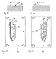
- FIG. 15 shows an upper part 84 of an injection molding tool for producing the profile arrangement according to the invention.
- a cavity 86 of the upper part 84 has a portion 88 for forming the carrier part and a groove 90 for inserting the switching strip profile.
- Channels 92 are provided for supplying the flowable plastic during spraying.
- the presentation of the Fig. 16 shows a view on the cutting plane AA of Fig. 15 , Good to recognize the groove 90 for inserting the switching strip profile and the channels 92nd
- FIG. 17 shows a lower part 94 of an injection mold for producing the profile arrangement 70 according to the invention.
- a cavity 96 has recesses 98 for forming the ribs 80 and also channels 100 for feeding the plastic material.
- Fig. 18 The view of Fig. 18 on the cutting plane BB the Fig. 17 illustrates the design of the cavity 96, even if the recesses 98 for forming the ribs 80 in Fig. 18 are not recognizable.
- Fig. 19 the contact strip profile 76 is shown after the extrusion process and before it is inserted into the injection mold.
- Fig. 20 then shows the top 84 of the injection mold, wherein in the groove 90, the in Fig. 19 shown contact strip profile 76 is inserted.
- Fig. 21 shows the upper part 84 after the injection of the plastic for the support part 72 and after removing the lower part 94 of the injection mold, which in Fig. 17 is shown.
- the complete profile arrangement 70 according to the invention is now arranged in the upper part 84 and can be completely removed therefrom. Only the plastic material from the spray channels 92 still has to be removed from the carrier part 72.
- the carrier part 72 after removal from the injection mold but a substantially ready to install component, only the wire strands in the conductors of the switching strip must still be contacted electrically.
- the wire strands can be contacted before inserting the contact strip profile in the groove 90. Together with the injection of the plastic for the support member 72 can then be made a seal of the two ends of the switching strip profile, which would otherwise have to be made after contacting. Surprisingly, it has been found that such automatic sealing of the ends of the switching strip profile is possible together with the injection of the plastic for the carrier part 72. As a result, a further step can be saved.
Landscapes
- Engineering & Computer Science (AREA)
- Mechanical Engineering (AREA)
- Manufacturing & Machinery (AREA)
- Injection Moulding Of Plastics Or The Like (AREA)
- Moulds For Moulding Plastics Or The Like (AREA)
- Seal Device For Vehicle (AREA)
- Manufacture Of Switches (AREA)
Applications Claiming Priority (1)
| Application Number | Priority Date | Filing Date | Title |
|---|---|---|---|
| DE102007050352A DE102007050352A1 (de) | 2007-10-10 | 2007-10-10 | Profilanordnung und Verfahren zum Herstellen einer Profilanordnung |
Publications (3)
| Publication Number | Publication Date |
|---|---|
| EP2048014A2 true EP2048014A2 (fr) | 2009-04-15 |
| EP2048014A3 EP2048014A3 (fr) | 2009-08-19 |
| EP2048014B1 EP2048014B1 (fr) | 2016-08-17 |
Family
ID=39885240
Family Applications (1)
| Application Number | Title | Priority Date | Filing Date |
|---|---|---|---|
| EP08016345.4A Not-in-force EP2048014B1 (fr) | 2007-10-10 | 2008-09-17 | Agencement de profilé et procédé de fabrication d'un agencement de profilé |
Country Status (5)
| Country | Link |
|---|---|
| US (1) | US20090136716A1 (fr) |
| EP (1) | EP2048014B1 (fr) |
| JP (1) | JP2009090667A (fr) |
| KR (1) | KR20090037335A (fr) |
| DE (1) | DE102007050352A1 (fr) |
Cited By (5)
| Publication number | Priority date | Publication date | Assignee | Title |
|---|---|---|---|---|
| US8493081B2 (en) | 2009-12-08 | 2013-07-23 | Magna Closures Inc. | Wide activation angle pinch sensor section and sensor hook-on attachment principle |
| EP2620577A1 (fr) * | 2012-01-27 | 2013-07-31 | Mayser GmbH & Co. KG | méthode de fixation d'un profilé anti-pincement sur un support, profilé et système anti-pincement |
| CN104228983A (zh) * | 2013-06-13 | 2014-12-24 | 通用汽车环球科技运作有限责任公司 | 机动车的侧扰流板装置 |
| US9234979B2 (en) | 2009-12-08 | 2016-01-12 | Magna Closures Inc. | Wide activation angle pinch sensor section |
| DE102012214289B4 (de) * | 2012-08-10 | 2016-03-31 | Mayser Gmbh & Co. Kg | Elektrische Schaltleiste und Verfahren zum Anspritzen einer Endkappe an ein elastisches Schaltleistenprofil |
Families Citing this family (2)
| Publication number | Priority date | Publication date | Assignee | Title |
|---|---|---|---|---|
| DE202009009028U1 (de) * | 2009-07-01 | 2010-12-30 | Brose Fahrzeugteile Gmbh & Co. Kommanditgesellschaft, Hallstadt | Kapazitive Sensoreinheit |
| CN110682495B (zh) * | 2019-09-20 | 2025-01-03 | 长春富维安道拓汽车饰件系统有限公司 | 一种用于镶嵌注塑的面料定位输送设备及面料定位方法 |
Citations (1)
| Publication number | Priority date | Publication date | Assignee | Title |
|---|---|---|---|---|
| DE10349650A1 (de) | 2003-10-20 | 2005-05-19 | Mayser Gmbh & Co. Kg | Profilanordnung für Einklemmschutz und Spritzgusswerkzeug |
Family Cites Families (9)
| Publication number | Priority date | Publication date | Assignee | Title |
|---|---|---|---|---|
| DE4339688A1 (de) * | 1993-11-22 | 1995-05-24 | Karlheinz Beckhausen | Nadelkontaktelement einer Sicherheitskontaktschiene |
| US6103168A (en) * | 1995-03-22 | 2000-08-15 | Gencorp Inc. | Method for manufacturing an integrally molded applique article for a vehicle with integral cosmetic and functional material |
| DE19602744C2 (de) * | 1996-01-19 | 1999-04-29 | Mayser Gmbh & Co | Sicherheitsschaltleistenanordnung |
| JP3472526B2 (ja) * | 2000-04-27 | 2003-12-02 | 日本圧着端子製造株式会社 | 集積回路素子用接続モジュールおよび接続モジュール付き集積回路素子 |
| US6782759B2 (en) * | 2001-07-09 | 2004-08-31 | Nartron Corporation | Anti-entrapment system |
| DE20207992U1 (de) * | 2002-05-23 | 2002-08-08 | Schüco International KG, 33609 Bielefeld | Sicherheitsdichtung und Fenster-, Tür-, Fassaden- oder Lichtdachkonstruktion |
| US20050117270A1 (en) * | 2003-10-20 | 2005-06-02 | Mayser Gmbh & Co. Kg | Profile arrangement for jamming protection and injection mould |
| DE102005059275B4 (de) * | 2005-12-12 | 2008-03-13 | Webasto Ag | Verblendungsvorrichtung für Fahrzeugdachsysteme mit öffnungsfähigem Deckel |
| DE202007004037U1 (de) * | 2007-03-22 | 2008-07-24 | Brose Fahrzeugteile Gmbh & Co. Kommanditgesellschaft, Hallstadt | Verkleidungselement |
-
2007
- 2007-10-10 DE DE102007050352A patent/DE102007050352A1/de not_active Ceased
-
2008
- 2008-09-17 EP EP08016345.4A patent/EP2048014B1/fr not_active Not-in-force
- 2008-09-30 JP JP2008253991A patent/JP2009090667A/ja active Pending
- 2008-10-09 KR KR1020080099241A patent/KR20090037335A/ko not_active Withdrawn
- 2008-10-10 US US12/287,693 patent/US20090136716A1/en not_active Abandoned
Patent Citations (1)
| Publication number | Priority date | Publication date | Assignee | Title |
|---|---|---|---|---|
| DE10349650A1 (de) | 2003-10-20 | 2005-05-19 | Mayser Gmbh & Co. Kg | Profilanordnung für Einklemmschutz und Spritzgusswerkzeug |
Cited By (6)
| Publication number | Priority date | Publication date | Assignee | Title |
|---|---|---|---|---|
| US8493081B2 (en) | 2009-12-08 | 2013-07-23 | Magna Closures Inc. | Wide activation angle pinch sensor section and sensor hook-on attachment principle |
| US9234979B2 (en) | 2009-12-08 | 2016-01-12 | Magna Closures Inc. | Wide activation angle pinch sensor section |
| US9417099B2 (en) | 2009-12-08 | 2016-08-16 | Magna Closures Inc. | Wide activation angle pinch sensor section |
| EP2620577A1 (fr) * | 2012-01-27 | 2013-07-31 | Mayser GmbH & Co. KG | méthode de fixation d'un profilé anti-pincement sur un support, profilé et système anti-pincement |
| DE102012214289B4 (de) * | 2012-08-10 | 2016-03-31 | Mayser Gmbh & Co. Kg | Elektrische Schaltleiste und Verfahren zum Anspritzen einer Endkappe an ein elastisches Schaltleistenprofil |
| CN104228983A (zh) * | 2013-06-13 | 2014-12-24 | 通用汽车环球科技运作有限责任公司 | 机动车的侧扰流板装置 |
Also Published As
| Publication number | Publication date |
|---|---|
| EP2048014B1 (fr) | 2016-08-17 |
| EP2048014A3 (fr) | 2009-08-19 |
| KR20090037335A (ko) | 2009-04-15 |
| DE102007050352A1 (de) | 2009-04-16 |
| JP2009090667A (ja) | 2009-04-30 |
| US20090136716A1 (en) | 2009-05-28 |
Similar Documents
| Publication | Publication Date | Title |
|---|---|---|
| EP2048014B1 (fr) | Agencement de profilé et procédé de fabrication d'un agencement de profilé | |
| DE102009021225B4 (de) | Öffnungs- und Schliessvorrichtung und Verfahren zum Herstellen eines Sensorstützelements | |
| EP1370436B1 (fr) | Ensemble joint | |
| EP2142394B1 (fr) | Système de guidage pour vitre mobile d'un véhicule automobile | |
| DE10158401B4 (de) | Moduldach für ein Kraftfahrzeug und Verfahren zu seiner Montage | |
| EP2304751A1 (fr) | Baguette de commutation pour la détection d'obstacles et dispositif pour la détection d'obstacles | |
| EP2620577B1 (fr) | méthode de fixation d'un profilé anti-pincement sur un support, profilé et système anti-pincement | |
| DE10017169A1 (de) | Deckel eines Fahrzeugdaches mit Kunststoffrahmen und Randspaltdichtung sowie Verfahren zur Herstellung eines solchen Deckels | |
| EP2799650B1 (fr) | Composants électriques de véhicule automobile | |
| DE102019130581A1 (de) | Kopplungsstruktur und Verfahren zum Herstellen eines Berührungssensors | |
| DE10220187B4 (de) | Vorrichtung zum Erkennen eines Hindernisses in dem Öffnungsbereich eines bewegbaren Schließelements eines Kraftfahrzeugs | |
| AT503044A4 (de) | Fixierelement für elektrische leiter, leiterstruktur-bauteil und verfahren zu dessen herstellung | |
| DE102008010547B3 (de) | Abdeckleiste für Kraftfahrzeuge | |
| EP1526241B1 (fr) | Arrangement anti-pincement et moule d'injection | |
| DE19725777A1 (de) | Befestigungsanordnung an dem Rand einer Scheibe, insbesondere Kraftfahrzeugfenster-Scheibe | |
| DE19747942C2 (de) | Türabdichtungsvorrichtung | |
| DE102004055476B3 (de) | Verfahren zum Herstellen eines elastisch verformbaren Hohlprofils und Vorrichtung zum Erkennen eines Hindernisses in dem Öffnungsbereich eines kraftbetätigten Schliesselements, die ein solches Hohlprofil aufweist | |
| DE102006015687A1 (de) | Profil für Sensoren | |
| EP1080969A2 (fr) | Panneau de toit pour véhicule avec cadre en matière plastique et joint d'étanchéité de fente périphérique et procédé de fabrication d'un tel panneau | |
| WO2015040013A1 (fr) | Barre électrode pour un système de capteur capacitif d'un véhicule automobile | |
| DE102015219094A1 (de) | Kraftfahrzeug-Fensterscheibe sowie Verfahren zu deren Herstellung | |
| DE10046975B4 (de) | Elastisches Hohlprofil und Verfahren zu seiner Herstellung | |
| DE202006009247U1 (de) | Gehäuse für ein Türschloss mit Anschlussadapter | |
| DE102017004456A1 (de) | Dichtungsanordnung für eine Fahrzeugsäule und Verfahren zum Herstellen einer solchen Dichtungsanordnung | |
| EP2947229A1 (fr) | Fenêtre de toit et procédé de montage d'une fenêtre de toit |
Legal Events
| Date | Code | Title | Description |
|---|---|---|---|
| PUAI | Public reference made under article 153(3) epc to a published international application that has entered the european phase |
Free format text: ORIGINAL CODE: 0009012 |
|
| AK | Designated contracting states |
Kind code of ref document: A2 Designated state(s): AT BE BG CH CY CZ DE DK EE ES FI FR GB GR HR HU IE IS IT LI LT LU LV MC MT NL NO PL PT RO SE SI SK TR |
|
| AX | Request for extension of the european patent |
Extension state: AL BA MK RS |
|
| PUAL | Search report despatched |
Free format text: ORIGINAL CODE: 0009013 |
|
| AK | Designated contracting states |
Kind code of ref document: A3 Designated state(s): AT BE BG CH CY CZ DE DK EE ES FI FR GB GR HR HU IE IS IT LI LT LU LV MC MT NL NO PL PT RO SE SI SK TR |
|
| AX | Request for extension of the european patent |
Extension state: AL BA MK RS |
|
| RIC1 | Information provided on ipc code assigned before grant |
Ipc: B60J 10/08 20060101ALI20090716BHEP Ipc: B29C 45/14 20060101ALI20090716BHEP Ipc: B60J 10/00 20060101AFI20081219BHEP |
|
| 17P | Request for examination filed |
Effective date: 20100119 |
|
| AKX | Designation fees paid |
Designated state(s): AT BE BG CH CY CZ DE DK EE ES FI FR GB GR HR HU IE IS IT LI LT LU LV MC MT NL NO PL PT RO SE SI SK TR |
|
| 17Q | First examination report despatched |
Effective date: 20140912 |
|
| GRAP | Despatch of communication of intention to grant a patent |
Free format text: ORIGINAL CODE: EPIDOSNIGR1 |
|
| INTG | Intention to grant announced |
Effective date: 20150928 |
|
| GRAS | Grant fee paid |
Free format text: ORIGINAL CODE: EPIDOSNIGR3 |
|
| REG | Reference to a national code |
Ref country code: DE Ref legal event code: R079 Ref document number: 502008014511 Country of ref document: DE Free format text: PREVIOUS MAIN CLASS: B60J0010000000 Ipc: B60J0010800000 |
|
| INTG | Intention to grant announced |
Effective date: 20160121 |
|
| RIC1 | Information provided on ipc code assigned before grant |
Ipc: B60J 10/80 20160101AFI20160112BHEP |
|
| GRAA | (expected) grant |
Free format text: ORIGINAL CODE: 0009210 |
|
| AK | Designated contracting states |
Kind code of ref document: B1 Designated state(s): AT BE BG CH CY CZ DE DK EE ES FI FR GB GR HR HU IE IS IT LI LT LU LV MC MT NL NO PL PT RO SE SI SK TR |
|
| REG | Reference to a national code |
Ref country code: GB Ref legal event code: FG4D Free format text: NOT ENGLISH |
|
| REG | Reference to a national code |
Ref country code: CH Ref legal event code: EP |
|
| REG | Reference to a national code |
Ref country code: IE Ref legal event code: FG4D Free format text: LANGUAGE OF EP DOCUMENT: GERMAN |
|
| REG | Reference to a national code |
Ref country code: AT Ref legal event code: REF Ref document number: 820683 Country of ref document: AT Kind code of ref document: T Effective date: 20160915 |
|
| REG | Reference to a national code |
Ref country code: DE Ref legal event code: R096 Ref document number: 502008014511 Country of ref document: DE Ref country code: FR Ref legal event code: PLFP Year of fee payment: 9 |
|
| REG | Reference to a national code |
Ref country code: NL Ref legal event code: MP Effective date: 20160817 |
|
| REG | Reference to a national code |
Ref country code: LT Ref legal event code: MG4D |
|
| PG25 | Lapsed in a contracting state [announced via postgrant information from national office to epo] |
Ref country code: NL Free format text: LAPSE BECAUSE OF FAILURE TO SUBMIT A TRANSLATION OF THE DESCRIPTION OR TO PAY THE FEE WITHIN THE PRESCRIBED TIME-LIMIT Effective date: 20160817 Ref country code: LT Free format text: LAPSE BECAUSE OF FAILURE TO SUBMIT A TRANSLATION OF THE DESCRIPTION OR TO PAY THE FEE WITHIN THE PRESCRIBED TIME-LIMIT Effective date: 20160817 Ref country code: IT Free format text: LAPSE BECAUSE OF FAILURE TO SUBMIT A TRANSLATION OF THE DESCRIPTION OR TO PAY THE FEE WITHIN THE PRESCRIBED TIME-LIMIT Effective date: 20160817 Ref country code: FI Free format text: LAPSE BECAUSE OF FAILURE TO SUBMIT A TRANSLATION OF THE DESCRIPTION OR TO PAY THE FEE WITHIN THE PRESCRIBED TIME-LIMIT Effective date: 20160817 Ref country code: NO Free format text: LAPSE BECAUSE OF FAILURE TO SUBMIT A TRANSLATION OF THE DESCRIPTION OR TO PAY THE FEE WITHIN THE PRESCRIBED TIME-LIMIT Effective date: 20161117 Ref country code: HR Free format text: LAPSE BECAUSE OF FAILURE TO SUBMIT A TRANSLATION OF THE DESCRIPTION OR TO PAY THE FEE WITHIN THE PRESCRIBED TIME-LIMIT Effective date: 20160817 |
|
| PG25 | Lapsed in a contracting state [announced via postgrant information from national office to epo] |
Ref country code: PT Free format text: LAPSE BECAUSE OF FAILURE TO SUBMIT A TRANSLATION OF THE DESCRIPTION OR TO PAY THE FEE WITHIN THE PRESCRIBED TIME-LIMIT Effective date: 20161219 Ref country code: BE Free format text: LAPSE BECAUSE OF NON-PAYMENT OF DUE FEES Effective date: 20160930 Ref country code: SE Free format text: LAPSE BECAUSE OF FAILURE TO SUBMIT A TRANSLATION OF THE DESCRIPTION OR TO PAY THE FEE WITHIN THE PRESCRIBED TIME-LIMIT Effective date: 20160817 Ref country code: ES Free format text: LAPSE BECAUSE OF FAILURE TO SUBMIT A TRANSLATION OF THE DESCRIPTION OR TO PAY THE FEE WITHIN THE PRESCRIBED TIME-LIMIT Effective date: 20160817 Ref country code: GR Free format text: LAPSE BECAUSE OF FAILURE TO SUBMIT A TRANSLATION OF THE DESCRIPTION OR TO PAY THE FEE WITHIN THE PRESCRIBED TIME-LIMIT Effective date: 20161118 Ref country code: LV Free format text: LAPSE BECAUSE OF FAILURE TO SUBMIT A TRANSLATION OF THE DESCRIPTION OR TO PAY THE FEE WITHIN THE PRESCRIBED TIME-LIMIT Effective date: 20160817 Ref country code: PL Free format text: LAPSE BECAUSE OF FAILURE TO SUBMIT A TRANSLATION OF THE DESCRIPTION OR TO PAY THE FEE WITHIN THE PRESCRIBED TIME-LIMIT Effective date: 20160817 |
|
| PG25 | Lapsed in a contracting state [announced via postgrant information from national office to epo] |
Ref country code: EE Free format text: LAPSE BECAUSE OF FAILURE TO SUBMIT A TRANSLATION OF THE DESCRIPTION OR TO PAY THE FEE WITHIN THE PRESCRIBED TIME-LIMIT Effective date: 20160817 Ref country code: RO Free format text: LAPSE BECAUSE OF FAILURE TO SUBMIT A TRANSLATION OF THE DESCRIPTION OR TO PAY THE FEE WITHIN THE PRESCRIBED TIME-LIMIT Effective date: 20160817 |
|
| REG | Reference to a national code |
Ref country code: CH Ref legal event code: PL |
|
| REG | Reference to a national code |
Ref country code: DE Ref legal event code: R097 Ref document number: 502008014511 Country of ref document: DE |
|
| PG25 | Lapsed in a contracting state [announced via postgrant information from national office to epo] |
Ref country code: SK Free format text: LAPSE BECAUSE OF FAILURE TO SUBMIT A TRANSLATION OF THE DESCRIPTION OR TO PAY THE FEE WITHIN THE PRESCRIBED TIME-LIMIT Effective date: 20160817 Ref country code: BG Free format text: LAPSE BECAUSE OF FAILURE TO SUBMIT A TRANSLATION OF THE DESCRIPTION OR TO PAY THE FEE WITHIN THE PRESCRIBED TIME-LIMIT Effective date: 20161117 Ref country code: CZ Free format text: LAPSE BECAUSE OF FAILURE TO SUBMIT A TRANSLATION OF THE DESCRIPTION OR TO PAY THE FEE WITHIN THE PRESCRIBED TIME-LIMIT Effective date: 20160817 Ref country code: DK Free format text: LAPSE BECAUSE OF FAILURE TO SUBMIT A TRANSLATION OF THE DESCRIPTION OR TO PAY THE FEE WITHIN THE PRESCRIBED TIME-LIMIT Effective date: 20160817 |
|
| PLBE | No opposition filed within time limit |
Free format text: ORIGINAL CODE: 0009261 |
|
| STAA | Information on the status of an ep patent application or granted ep patent |
Free format text: STATUS: NO OPPOSITION FILED WITHIN TIME LIMIT |
|
| REG | Reference to a national code |
Ref country code: IE Ref legal event code: MM4A |
|
| PG25 | Lapsed in a contracting state [announced via postgrant information from national office to epo] |
Ref country code: MC Free format text: LAPSE BECAUSE OF FAILURE TO SUBMIT A TRANSLATION OF THE DESCRIPTION OR TO PAY THE FEE WITHIN THE PRESCRIBED TIME-LIMIT Effective date: 20160817 |
|
| 26N | No opposition filed |
Effective date: 20170518 |
|
| PG25 | Lapsed in a contracting state [announced via postgrant information from national office to epo] |
Ref country code: CH Free format text: LAPSE BECAUSE OF NON-PAYMENT OF DUE FEES Effective date: 20160930 Ref country code: LI Free format text: LAPSE BECAUSE OF NON-PAYMENT OF DUE FEES Effective date: 20160930 Ref country code: IE Free format text: LAPSE BECAUSE OF NON-PAYMENT OF DUE FEES Effective date: 20160917 |
|
| PG25 | Lapsed in a contracting state [announced via postgrant information from national office to epo] |
Ref country code: SI Free format text: LAPSE BECAUSE OF FAILURE TO SUBMIT A TRANSLATION OF THE DESCRIPTION OR TO PAY THE FEE WITHIN THE PRESCRIBED TIME-LIMIT Effective date: 20160817 Ref country code: LU Free format text: LAPSE BECAUSE OF NON-PAYMENT OF DUE FEES Effective date: 20160917 |
|
| REG | Reference to a national code |
Ref country code: FR Ref legal event code: PLFP Year of fee payment: 10 |
|
| REG | Reference to a national code |
Ref country code: AT Ref legal event code: MM01 Ref document number: 820683 Country of ref document: AT Kind code of ref document: T Effective date: 20160917 |
|
| REG | Reference to a national code |
Ref country code: BE Ref legal event code: MM Effective date: 20160930 |
|
| PG25 | Lapsed in a contracting state [announced via postgrant information from national office to epo] |
Ref country code: AT Free format text: LAPSE BECAUSE OF NON-PAYMENT OF DUE FEES Effective date: 20160917 |
|
| PG25 | Lapsed in a contracting state [announced via postgrant information from national office to epo] |
Ref country code: HU Free format text: LAPSE BECAUSE OF FAILURE TO SUBMIT A TRANSLATION OF THE DESCRIPTION OR TO PAY THE FEE WITHIN THE PRESCRIBED TIME-LIMIT; INVALID AB INITIO Effective date: 20080917 Ref country code: CY Free format text: LAPSE BECAUSE OF FAILURE TO SUBMIT A TRANSLATION OF THE DESCRIPTION OR TO PAY THE FEE WITHIN THE PRESCRIBED TIME-LIMIT Effective date: 20160817 |
|
| PG25 | Lapsed in a contracting state [announced via postgrant information from national office to epo] |
Ref country code: IS Free format text: LAPSE BECAUSE OF FAILURE TO SUBMIT A TRANSLATION OF THE DESCRIPTION OR TO PAY THE FEE WITHIN THE PRESCRIBED TIME-LIMIT Effective date: 20160817 Ref country code: MT Free format text: LAPSE BECAUSE OF FAILURE TO SUBMIT A TRANSLATION OF THE DESCRIPTION OR TO PAY THE FEE WITHIN THE PRESCRIBED TIME-LIMIT Effective date: 20160817 Ref country code: TR Free format text: LAPSE BECAUSE OF FAILURE TO SUBMIT A TRANSLATION OF THE DESCRIPTION OR TO PAY THE FEE WITHIN THE PRESCRIBED TIME-LIMIT Effective date: 20160817 |
|
| REG | Reference to a national code |
Ref country code: FR Ref legal event code: PLFP Year of fee payment: 11 |
|
| PGFP | Annual fee paid to national office [announced via postgrant information from national office to epo] |
Ref country code: DE Payment date: 20190924 Year of fee payment: 12 Ref country code: FR Payment date: 20190924 Year of fee payment: 12 |
|
| PGFP | Annual fee paid to national office [announced via postgrant information from national office to epo] |
Ref country code: GB Payment date: 20190924 Year of fee payment: 12 |
|
| REG | Reference to a national code |
Ref country code: DE Ref legal event code: R119 Ref document number: 502008014511 Country of ref document: DE |
|
| GBPC | Gb: european patent ceased through non-payment of renewal fee |
Effective date: 20200917 |
|
| PG25 | Lapsed in a contracting state [announced via postgrant information from national office to epo] |
Ref country code: DE Free format text: LAPSE BECAUSE OF NON-PAYMENT OF DUE FEES Effective date: 20210401 Ref country code: FR Free format text: LAPSE BECAUSE OF NON-PAYMENT OF DUE FEES Effective date: 20200930 |
|
| PG25 | Lapsed in a contracting state [announced via postgrant information from national office to epo] |
Ref country code: GB Free format text: LAPSE BECAUSE OF NON-PAYMENT OF DUE FEES Effective date: 20200917 |