EP2048033A1 - Hebelgesteuertes, versenkbares Dachgepäckträgersystem für Kraftfahrzeug und entsprechendes Fahrzeug - Google Patents
Hebelgesteuertes, versenkbares Dachgepäckträgersystem für Kraftfahrzeug und entsprechendes Fahrzeug Download PDFInfo
- Publication number
- EP2048033A1 EP2048033A1 EP08166404A EP08166404A EP2048033A1 EP 2048033 A1 EP2048033 A1 EP 2048033A1 EP 08166404 A EP08166404 A EP 08166404A EP 08166404 A EP08166404 A EP 08166404A EP 2048033 A1 EP2048033 A1 EP 2048033A1
- Authority
- EP
- European Patent Office
- Prior art keywords
- lever
- vehicle
- axis
- gallery system
- gallery
- Prior art date
- Legal status (The legal status is an assumption and is not a legal conclusion. Google has not performed a legal analysis and makes no representation as to the accuracy of the status listed.)
- Withdrawn
Links
- 238000000034 method Methods 0.000 description 11
- 230000008901 benefit Effects 0.000 description 6
- 239000000446 fuel Substances 0.000 description 2
- 230000006978 adaptation Effects 0.000 description 1
- 238000005452 bending Methods 0.000 description 1
- 239000000470 constituent Substances 0.000 description 1
- 230000002452 interceptive effect Effects 0.000 description 1
- 230000035515 penetration Effects 0.000 description 1
Images



Classifications
-
- B—PERFORMING OPERATIONS; TRANSPORTING
- B60—VEHICLES IN GENERAL
- B60R—VEHICLES, VEHICLE FITTINGS, OR VEHICLE PARTS, NOT OTHERWISE PROVIDED FOR
- B60R9/00—Supplementary fittings on vehicle exterior for carrying loads, e.g. luggage, sports gear or the like
- B60R9/04—Carriers associated with vehicle roof
- B60R9/045—Carriers being adjustable or transformable, e.g. expansible, collapsible
Definitions
- the field of the invention is that of automotive equipment, and more specifically galleries for such vehicles.
- Galleries have long been known, allowing objects to be transported outside the vehicle, and in particular on the pavilion of the vehicle. At first, these galleries were in the form of a fixed assembly defining a storage area on the pavilion. Depending on the case, this gallery was fixed or removable.
- Another improvement has been to equip some vehicles, including minivan, utility or station wagon, fixed spars, extending substantially parallel to the main axis of the vehicle. It is then easier to fix ties on these spars, if necessary, to form a gallery.
- the invention particularly aims to overcome these disadvantages of the prior art.
- an object of the invention is to provide a gallery technique for a motor vehicle that is simple to use and to manipulate by a user, without particular tools.
- the invention also aims to provide such a technique, which is reliable, inexpensive and simple to produce and mount.
- Another object of the invention is to provide such a gallery technique solving the problem of storage sleepers, when they are not used.
- Yet another object of the invention is to provide such a gallery technique, having good aesthetic and ergonomic qualities.
- a gallery system for a motor vehicle comprising at least two cross members integral with two longitudinal members.
- a lever acting respectively on at least one of the longitudinal members (and thus on the end of at least two crosspieces), is provided to change the position of the gallery.
- the mass of the beams and the sleepers associated with them is supported by four feet (or more, if the spacing between the sleepers or the maximum load justifies it) that can tilt simultaneously to allow the passage between the retracted and portage positions.
- said lever is secured by a pivot joint to said spar.
- the spar can remain substantially horizontal when moving from the retracted position to the carrying position and vice versa.
- said pivot joint has as axis said second axis.
- the gallery system advantageously comprises, in addition, means for guiding an end of said lever intended to cooperate with at least one slide formed and / or fixed on said vehicle.
- such a gallery system comprises means for locking said guide means in at least one predetermined position of said slideway.
- said locking means comprise means for locking said guide means in said predetermined position.
- said longitudinal members can be rotatably mounted on said vehicle.
- said sleepers slide relative to securing means carried by the longitudinal members during the passage of said retracted position to said carrying position or vice versa.
- the sleepers are not forced to switch to follow the movement of the rails and can maintain a horizontal position. Moreover, such sliding makes it possible to simply catch the variation in distance between the means for securing the crosspieces to the side members, due to the tilting of the latter. It is therefore not necessary to provide sleepers of variable length (which is however possible in other embodiments).
- At least one of said securing means has a fork forming said lever, between the branches of which is inserted an end of one of said sleepers.
- a gallery system as described above comprises at least one gripping element secured to at least a first branch of one of said forks.
- said gripping element is secured to the two branches of said fork.
- said gripping element connects the ends of said fork.
- At least one end of each of said crosspieces has at least one guide rail cooperating with at least one protrusion integral with at least one of said branches of said fork.
- Two symmetrical slides, and two corresponding projections, may in particular be provided.
- the crosspieces in said retracted position, at least partially penetrate into housings provided for this purpose in the roof.
- these housings are designed so that the cross members are flush with the roof in the retracted position.
- the crossmembers may also only be placed on the roof in the retracted position.
- the invention also relates to motor vehicles equipped with a gallery system as described above.
- the general principle of the invention is therefore based on the implementation of articulated gallery feet and one (or more) lever (s) to allow a user to deploy in a carrying position, or to fold, manually, quickly and in a simple way a retractable gallery for roof of vehicle according to its needs.
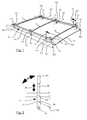
- the figure 1 illustrates a first embodiment of the invention in a carrying position.
- the gallery system 13 is mounted on the roof 12 of a motor vehicle (utility type in this example implementation). It comprises two longitudinal members 14 secured to three cross members 15 forming a rigid assembly. The longitudinal members 14 are arranged substantially in the direction of movement of the vehicle and the cross members 15 transversely.
- the longitudinal members 14 are each supported by three substantially identical feet 16, integral with the "V" 121 side corners of the roof and spaced regularly.
- Each foot 16 is articulated in rotation along a first axis of articulation 161 with respect to the angle 121 and along a second axis of articulation 162 with the corresponding spar 14, the distance between the axes 161 and 162 being constant for all the feet .
- each section of spar between two feet forms with them a deformable parallelogram allowing the passage of the carrying position as shown to a retracted position by rotation in the direction of the arrow 110.
- Two levers 17 are each secured respectively to one of the angles 121 in the vicinity of one of the feet 16.
- the axis 171 of these levers is separate but aligned with the axes 161 of the feet 16.
- Each lever 17 comprises a hinge axis 172 with the spar on which it acts, separated from the axis 171 by a distance equal to the distance between the axes 161 and 162, of to also form a side of a parallelogram with the spar and feet.
- the lever 17 when pivoting about its axis therefore drives the beam up or down because of the pivot joint between them.
- lever 17 is integrated with, or formed by, one of the legs 16.
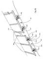
- the figure 2 specifies in a detailed view the constituent elements of the lever 17.
- the body 21 of the lever is extended by an arm 22 of variable length in the direction of the arrow 24 at the end of which is fixed a handle 23 including ergonomic areas to facilitate its grip.
- the arm 22 can be retracted to facilitate storage or deployed to a working length so as to benefit from a greater "lever arm” to change the position of the gallery.
- latching locking means 25 make it possible to lock the lever in three predetermined positions by being inserted into a blind hole 26 provided for this purpose in the body 21 of the lever 17.
- a movable ring secured to the pawl may be mounted on the handle of the lever to disengage or engage the pawl on the wheel.
- the figure 10 schematically illustrates a second embodiment of the invention in a carrying position.
- the gallery system is in the form of two identical modules 1001 and 1002 respectively mounted on the front and rear of the roof of the vehicle. These modules are connected to each other by fasteners 1010 provided for this purpose, to form from the two modules a gallery covering substantially the entire surface of the flag in the carrying position.
- Each of these modules comprises three cross members 1003 secured to two longitudinal members 1004.
- Each spar 1004 is supported by two rocking feet 1005 articulated in rotation about an axis 1005A to the spar and about an axis 1005B to the flag.
- the feet 1005 are equipped with levers 1006 actuated by a handle 1007, in the form of a handle in this embodiment.
- each lever 1006 having the general shape of a "8"
- the fastening elements 1010 also lock the gallery in the carrying position, preventing the modules from moving away from each other, and thus the feet from tilting to the retracted position.
- the foot 1005 has a central recess to allow the passage of fingers with one hand.
- the handle 1007 of the lever 1006 can thus be easily grasped from above, to raise the gallery to the carrying position.
- the lever 1006 is pivotally mounted on the axis 1005A on two bearings 1102.
- the end of the lever 1006 opposite the handle 1007 comprises a rod 1103. parallel to the axis 1005A, a protruding portion 1103A enters a horizontal slide 1104 formed in the support 1101 to guide the lever 1006 along the support when actuated.
- Legs 1105 and 1106 formed in the support 1101 also make it possible to keep the lever 1006 stationary.
- the rod 1103 When the rod 1103 reaches a predetermined position opposite the slide, after passing under the body of the hook 1109, it is housed in a groove 1108 formed in the support 1101, provided to block its progression, and a hook 1109 is placed on the projecting portion 1103A, under the action of a spring 1111 connected eccentrically to the axis 1110 of the hook, to lock the rod 1103 in this predetermined position.
- the crossbar 34 is placed on the flag 91 in the retracted position.
- at least one of the longitudinal members 33 can be articulated on a support 92 secured to the roof 91 allowing the hinge axis 331 of the spar 33 to be substantially in the plane of the roof.
- Another approach may involve an intermediate technique where the cross is only partially embedded, its upper part protruding from the flag.
- the vehicle concerned by the invention may in particular be a passenger vehicle type sedan, station wagon or minivan, a utility vehicle, a coach ...
- the gallery system 31 mounted on a roof 32 of the vehicle, comprises two movable spars 33, of which only one is shown on the figure 3 , carrying solidarity means hinged together with three cross members 34.
- the spar 33 can swing about the axis 331 (as shown by the arrow 35) relative to the flag 32 to allow the passage of the carrying position, as illustrated on the figure 3 , in a retracted position. It carries securing means comprising three forks 332 with two branches 333 between which is inserted one end of one of the cross members 34. Each fork 332 constitutes a lever 331 axis coincident with that of the spar on which one can act to make rotate the spar 33. A gripping handle 334 connecting the end of the branches 333 allows to actuate this lever.
- the handle of the lever 51 is attached to a single leg 53 of the lever fork 51.
- each end of the crosspieces 34 comprises, in this particular embodiment, a guiding slide 41 in the form of a through opening lumen.
- each cross member is provided with a first groove on a lateral face vis-à-vis a second groove on its opposite side face.
- a projecting element 42 in the form of a dovetail, integral with one of the branches of the lever fork, is slidably mounted in the slideway 41 to drive the crosshead downwards as it moves from its carrying position to its position. retracted or upward when reversing.
- the lever pivots in the direction of the arrow 43, and the projecting element 42 slides towards the center of the crossbar, driving it towards the bottom
- securing means such as rings or strapping hooks 36 are also provided on the spar 33 to allow stowing objects transported on the gallery.
- the end of the sleepers may also include additional securement means 61, as shown in the detail view of the figure 6 .
- a roller 37 is mounted on the crossbar located at the rear of the gallery.
Landscapes
- Engineering & Computer Science (AREA)
- Mechanical Engineering (AREA)
- Fittings On The Vehicle Exterior For Carrying Loads, And Devices For Holding Or Mounting Articles (AREA)
Applications Claiming Priority (2)
| Application Number | Priority Date | Filing Date | Title |
|---|---|---|---|
| FR0707121A FR2922169A1 (fr) | 2007-10-10 | 2007-10-10 | Systeme de galerie escamotable pour vehicule automobile, commande par un levier, et vehicule correspondant |
| FR0850825A FR2922170A1 (fr) | 2007-10-10 | 2008-02-08 | Systeme de galerie escamotable pour vehicule automobile, commande par un levier, et vehicule correspondant |
Publications (1)
| Publication Number | Publication Date |
|---|---|
| EP2048033A1 true EP2048033A1 (de) | 2009-04-15 |
Family
ID=40230006
Family Applications (1)
| Application Number | Title | Priority Date | Filing Date |
|---|---|---|---|
| EP08166404A Withdrawn EP2048033A1 (de) | 2007-10-10 | 2008-10-10 | Hebelgesteuertes, versenkbares Dachgepäckträgersystem für Kraftfahrzeug und entsprechendes Fahrzeug |
Country Status (1)
| Country | Link |
|---|---|
| EP (1) | EP2048033A1 (de) |
Cited By (6)
| Publication number | Priority date | Publication date | Assignee | Title |
|---|---|---|---|---|
| DE102009022590A1 (de) * | 2009-05-26 | 2010-12-16 | GM Global Technology Operations, Inc., Detroit | Kraftfahrzeug-Dachgepäckträger |
| FR2946595A1 (fr) * | 2009-06-15 | 2010-12-17 | Peugeot Citroen Automobiles Sa | Systeme de verrouillage d'une barre escamotable de toit. |
| US8100306B2 (en) * | 2009-03-13 | 2012-01-24 | Ford Global Technologies | Roof bar for a motor vehicle |
| US8978946B2 (en) * | 2009-03-13 | 2015-03-17 | Ford Global Technologies | Roof bar for a motor vehicle |
| WO2017075123A1 (en) * | 2015-10-27 | 2017-05-04 | Horizon Global Corporation | Load support system for vehicle roof |
| US10953807B2 (en) | 2018-09-12 | 2021-03-23 | Toyota Motor Engineering & Manufacturing North America, Inc. | Hideaway roof rack for fuel economy |
Citations (7)
| Publication number | Priority date | Publication date | Assignee | Title |
|---|---|---|---|---|
| DE3719974A1 (de) * | 1986-06-20 | 1987-12-23 | Volkswagen Ag | Dachgepaecktraegersystem |
| US5096106A (en) * | 1990-06-13 | 1992-03-17 | Huron/St. Clair Incorporated | Luggage carrier with pop-up frame |
| FR2828854A1 (fr) * | 2001-08-21 | 2003-02-28 | Renault | Ensemble de barres de toit pour un vehicule automobile |
| US20030141735A1 (en) * | 2002-01-04 | 2003-07-31 | Nissan Design America Inc. | Pop-up roof rack |
| DE10222161A1 (de) * | 2002-05-17 | 2003-11-27 | Bosch Gmbh Robert | Integrierter Lastträger für ein Kraftfahrzeug |
| DE202004004302U1 (de) * | 2003-04-01 | 2004-08-12 | ArvinMeritor Technology, LLC, Troy | Modulares Fahrzeugdach mit versenkbarem Dachgepäckträger |
| US20070102466A1 (en) * | 2005-10-12 | 2007-05-10 | Magna Car Top Systems Gmbh | Vehicle having a roof rack |
-
2008
- 2008-10-10 EP EP08166404A patent/EP2048033A1/de not_active Withdrawn
Patent Citations (7)
| Publication number | Priority date | Publication date | Assignee | Title |
|---|---|---|---|---|
| DE3719974A1 (de) * | 1986-06-20 | 1987-12-23 | Volkswagen Ag | Dachgepaecktraegersystem |
| US5096106A (en) * | 1990-06-13 | 1992-03-17 | Huron/St. Clair Incorporated | Luggage carrier with pop-up frame |
| FR2828854A1 (fr) * | 2001-08-21 | 2003-02-28 | Renault | Ensemble de barres de toit pour un vehicule automobile |
| US20030141735A1 (en) * | 2002-01-04 | 2003-07-31 | Nissan Design America Inc. | Pop-up roof rack |
| DE10222161A1 (de) * | 2002-05-17 | 2003-11-27 | Bosch Gmbh Robert | Integrierter Lastträger für ein Kraftfahrzeug |
| DE202004004302U1 (de) * | 2003-04-01 | 2004-08-12 | ArvinMeritor Technology, LLC, Troy | Modulares Fahrzeugdach mit versenkbarem Dachgepäckträger |
| US20070102466A1 (en) * | 2005-10-12 | 2007-05-10 | Magna Car Top Systems Gmbh | Vehicle having a roof rack |
Cited By (8)
| Publication number | Priority date | Publication date | Assignee | Title |
|---|---|---|---|---|
| US8100306B2 (en) * | 2009-03-13 | 2012-01-24 | Ford Global Technologies | Roof bar for a motor vehicle |
| US8978946B2 (en) * | 2009-03-13 | 2015-03-17 | Ford Global Technologies | Roof bar for a motor vehicle |
| DE102009022590A1 (de) * | 2009-05-26 | 2010-12-16 | GM Global Technology Operations, Inc., Detroit | Kraftfahrzeug-Dachgepäckträger |
| FR2946595A1 (fr) * | 2009-06-15 | 2010-12-17 | Peugeot Citroen Automobiles Sa | Systeme de verrouillage d'une barre escamotable de toit. |
| WO2010146286A3 (fr) * | 2009-06-15 | 2011-02-24 | Peugeot Citroën Automobiles SA | Système de verrouillage d'une barre escamotable de toit |
| WO2017075123A1 (en) * | 2015-10-27 | 2017-05-04 | Horizon Global Corporation | Load support system for vehicle roof |
| US20180326915A1 (en) * | 2015-10-27 | 2018-11-15 | Horizon Global Americas Inc. | Load support system for vehicle roof |
| US10953807B2 (en) | 2018-09-12 | 2021-03-23 | Toyota Motor Engineering & Manufacturing North America, Inc. | Hideaway roof rack for fuel economy |
Similar Documents
| Publication | Publication Date | Title |
|---|---|---|
| FR2990167A1 (fr) | Siege, notamment pour vehicule automobile | |
| EP2178484B1 (de) | Hebevorrichtung für einen rollstuhl | |
| FR2916390A1 (fr) | Nacelle pour siege de vehicule militaire | |
| EP2138353A1 (de) | Vorrichtung zum Versenken der hinteren Ablage eines Kraftfahrzeugs durch Dreh- und Schwenkantrieb | |
| WO2005007435A2 (fr) | Véhicule à toit ouvrant escamotable et procédé de rangement d'un tel toit, avec basculement horizontal. | |
| EP1597101A1 (de) | Versenkbares dach für ein fahrzeug | |
| EP1547856A1 (de) | Fahrzeugsitz | |
| EP2010405A1 (de) | Vorrichtung zum verriegeln eines versenkbaren dachs und mit solch einem system ausgestattetes fahrzeug | |
| FR2922170A1 (fr) | Systeme de galerie escamotable pour vehicule automobile, commande par un levier, et vehicule correspondant | |
| WO2004009387A2 (fr) | Dispositif adapte a faciliter l'introduction d'objets sous un toit replie dans un coffre de vehicule automobile | |
| FR2878433A1 (fr) | Dispositif de transfert et de chargement de fauteuil roulant a bord d'un vehicule | |
| FR2896207A1 (fr) | Vide poche escamotable pour planche de bord de vehicule automobile. | |
| FR2746059A1 (fr) | Porte laterale de vehicule automobile a cinematique d'ouverture perfectionnee | |
| EP1808330A2 (de) | Sitz für Kraftfahrzeug, der entlang einer ersten Achse x und einer zweiten Achse y beweglich ist, und Kraftfahrzeug, das einen solchen Sitz umfasst | |
| FR2936981A1 (fr) | Dispositif de toit ouvrant a commande manuelle pour vehicule notamment de type automobile | |
| FR2902724A1 (fr) | Agencement d'une tablette dans un caisson, notamment pour un vehicule automobile | |
| FR2908092A1 (fr) | Dispositif de chargement et/ou dechargement d'un vehicule de transport, module de plancher d'un vehicule de transport et vehicule de transport | |
| FR2881387A1 (fr) | Plancher mobile pour coffre a bagages d'automobile | |
| WO2016030639A1 (fr) | Siège pour véhicule comprenant un plancher de chargement | |
| FR2946595A1 (fr) | Systeme de verrouillage d'une barre escamotable de toit. | |
| FR2785579A1 (fr) | Agencement d'un siege, notamment pliable, dans un habitacle de vehicule automobile | |
| FR2820798A1 (fr) | Systeme d'entrainement en deplacement d'un panneau pour passagers arriere d'un vehicule | |
| FR3024680A1 (fr) | Siege de vehicule automobile et vehicule automobile equipe d’un tel siege | |
| FR2991927A1 (fr) | Siege escamotable | |
| FR2845950A1 (fr) | Toit escamotable pour vehicule |
Legal Events
| Date | Code | Title | Description |
|---|---|---|---|
| PUAI | Public reference made under article 153(3) epc to a published international application that has entered the european phase |
Free format text: ORIGINAL CODE: 0009012 |
|
| AK | Designated contracting states |
Kind code of ref document: A1 Designated state(s): AT BE BG CH CY CZ DE DK EE ES FI FR GB GR HR HU IE IS IT LI LT LU LV MC MT NL NO PL PT RO SE SI SK TR |
|
| AX | Request for extension of the european patent |
Extension state: AL BA MK RS |
|
| AKX | Designation fees paid | ||
| REG | Reference to a national code |
Ref country code: DE Ref legal event code: 8566 |
|
| STAA | Information on the status of an ep patent application or granted ep patent |
Free format text: STATUS: THE APPLICATION IS DEEMED TO BE WITHDRAWN |
|
| 18D | Application deemed to be withdrawn |
Effective date: 20091016 |