EP2048062A2 - Verbesserungen bei oder im Zusammenhang mit Fahrzeuglenkungen - Google Patents
Verbesserungen bei oder im Zusammenhang mit Fahrzeuglenkungen Download PDFInfo
- Publication number
- EP2048062A2 EP2048062A2 EP08166044A EP08166044A EP2048062A2 EP 2048062 A2 EP2048062 A2 EP 2048062A2 EP 08166044 A EP08166044 A EP 08166044A EP 08166044 A EP08166044 A EP 08166044A EP 2048062 A2 EP2048062 A2 EP 2048062A2
- Authority
- EP
- European Patent Office
- Prior art keywords
- drag link
- adjustment tube
- adjustment
- length
- drag
- Prior art date
- Legal status (The legal status is an assumption and is not a legal conclusion. Google has not performed a legal analysis and makes no representation as to the accuracy of the status listed.)
- Granted
Links
Images


Classifications
-
- B—PERFORMING OPERATIONS; TRANSPORTING
- B62—LAND VEHICLES FOR TRAVELLING OTHERWISE THAN ON RAILS
- B62D—MOTOR VEHICLES; TRAILERS
- B62D7/00—Steering linkage; Stub axles or their mountings
- B62D7/20—Links, e.g. track rods
-
- B—PERFORMING OPERATIONS; TRANSPORTING
- B62—LAND VEHICLES FOR TRAVELLING OTHERWISE THAN ON RAILS
- B62D—MOTOR VEHICLES; TRAILERS
- B62D9/00—Steering deflectable wheels not otherwise provided for
Definitions
- the present invention relates to a drag link for the steering mechanism of a vehicle and, more particularly, to a drag link for the steering mechanism of a truck.
- Figure 1 shows a standard steering mechanism 100 for use in a Light Commercial Vehicle (LCV) or a Heavy Goods Vehicle (HGV).
- LCV Light Commercial Vehicle
- HGV Heavy Goods Vehicle
- Figure 1 shows vehicle chassis rails 101, road wheels 102, front axle 103 and tie rod 104.
- the steering mechanism includes a steering wheel 105, steering column 106, a steering box 107, a Pitman arm or crank 108, a steering arm 108a and a drag link 109.
- the drag link 109 is mounted in the longitudinal or fore/aft direction, substantially parallel to the chassis rails 101.
- the drag link should be straight in order to maximise the efficiency of the system. However, it is rare to reach this ideal as the drag link must be shaped to allow the front left road wheel to turn right without fouling the drag link.
- the drag link 109 shown in Figure 1 is shaped in order to enable it to conform to the packaging constraints placed on it.
- the rotational motion is transmitted by the steering column 106 to the steering box 107.
- the crank 108 translates the rotational motion into substantially linear motion.
- the linear motion is then transmitted by the drag link 109 to the steering arm 108a which is perpendicular to the road wheel 102.
- the tie rod 104 connects the turning force applied to the wheels 102 in response to the turning of the steering wheel 105.
- the central position of the steering wheel 105 equates to the situation wherein the wheels 102 are pointing straight ahead.
- this situation cannot be attained without adjustment of the steering system.
- Figure 2 shows a steering system 110 incorporating an adjustable length drag link 111.
- the steering system 110 includes an adjustable length drag link 111; a fixed ball joint 112 adjacent the wheel 102 and an adjustable ball joint 113 adjacent the crank 108.
- the adjustable ball joint 113 is mounted to the crank using a standard pin connector 114.
- the adjustable ball joint 113 is mounted to the drag link 111 using a screw threaded connection.
- An internal surface of the drag link 111 adjacent the ball joint 113 is screw threaded and the adjustable ball joint 113 has a male connector that is also screw-threaded.
- the adjustable ball joint 113 can be rotated relative to the drag link 110.
- the pin connector 114 In order to re-engage with the crank 108, the pin connector 114 must be aligned with the crank 108. Therefore the minimum adjustment of the length of the drag link 111 is limited to the pitch of the thread provided on the internal surface of the drag link 111 because the adjustable ball joint must be rotated in multiples of 360° in order to re-engage with the crank 108.
- a further problem that is encountered with steering systems used in trucks in which the drag link lies substantially parallel to the chassis rails, is that, in the case of an impact occurring in the vicinity of the drag link, the drag link may transmit forces from the impact through the steering mechanism to the steering column. In this event, undesirable forces may be transmitted from the drag link to the steering column, which may diminish the energy management performance of the steering system.
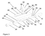
- a drag link for the steering system of a vehicle, the drag link comprising: a first drag link portion and a second drag link portion, an adjustment tube for connecting the first portion to the second portion to provide continuous variation in the length of the drag link; and at least one stopper ring configured to maintain the length of the drag link under normal load conditions and to allow the first and/or second portion to move relative to the adjustment tube under excessive axial load in order to manage the energy of the excessive load.
- the modified drag link provides two improved functions in comparison with a standard drag link. It enables the length of the drag link to be modified and/or adjusted without a minimum increment dependent upon the pitch of the screwthread. This allows a much more accurate alignment to be carried out between the wheel positioning and the steering wheel of the vehicle.
- the drag link is collapsible under excessive load conditions such as those that can arise during an impact. By providing a drag link that is collapsible the energy of the impact can be managed locally and the transmission of forces through the steering system to the steering wheel can be substantially reduced.
- the system can be adjusted on the vehicle without requiring a cycle of disassembly, adjustment, reassembly and checking. Both of these additional features are provided with little or no change to the overall packaging envelope of the drag link. As packaging space for the drag link can be limited, minimising the change in the packaging envelope of the drag link is important.
- the first drag link portion may further comprise a left-handed threaded pin and the second drag link portion may further comprise a right-handed threaded pin.
- the adjustment tube may have a left-handed threaded section and a right handed threaded section.
- the combination of opposing threads enables the continuous variation in length of the drag link.
- the adjustment tube As the adjustment tube is turned it either draws both threaded pins into the adjustment tube and thereby reduces the overall length of the drag link, or it gradually expels the threaded pins from the adjustment tube and thereby increases the overall length of the drag link.
- the drag link may further comprise a second stopper ring.
- the drag link system is symmetrical and therefore a second stopper ring is provided in order to enable the second threaded pin 40 to move relative to the second portion of the drag link under excessive load conditions.
- Each stopper ring may be configured to abut the respective threaded pin. Each stopper ring may also be sized to contact an inner surface of the respective drag link portion and to allow sliding contact with the inner surface of the respective drag link portion under excessive load conditions.
- the stopper rings are provided inside the respective first and second portions of the drag link so that their functionality cannot be compromised by inadvertent interplay with other vehicle components that are packaged adjacent the drag link. This configuration also ensures that changes to the envelope of the drag link itself are minimised. This enables the drag link to be retrofitted into any suitable vehicle steering system.
- the drag link may further comprise a protective sleeve and a clamp configured locally to deform or clamp the adjustment tube to prevent relative movement between the threaded pins and the adjustment tube.
- the protective sleeve and clamp are applied to the drag link once the length of the drag link has been optimised by turning the adjustment tube. Once the length of the drag link has been set, the protective sleeve and clamp are applied in order to prevent further unwanted changes in the length of the drag link.
- the protective sleeve may closely interface with the adjustment tube. Furthermore, the protective sleeve closely interfaces with the first and second drag link portions. By providing the close fittings between the various parts of the system, changes to the overall envelope of the drag link are minimised.
- the adjustment tube has an outer surface that may be configured to accommodate a tool to rotate the adjustment tube to adjust the length of the drag link.
- the provision of multiple faces for interfacing with, for example, a spanner or wrench facilitates the rotation of the adjustment tube with ease and accuracy.
- castellations or indentations may be provided around the periphery of the adjustment tube to op-operate with a tool such as a crescent wrench.
- the drag link may further comprise means for indicating the position of the first drag link portion relative to the adjustment tube.
- This indicating means may comprise a gauge on the first portion configured so that the edge of the adjustment tube overlaps the gauge and thereby indicates their relative position. The provision of a gauge allows the operative to confirm the extent of the adjustment in the length of the drag link.
- the drag link may be provided in a vehicle having chassis rails.
- the drag link may be configured to lie substantially parallel to the vehicle chassis rails.
- the drag link may be configured to lie substantially perpendicular to the vehicle chassis rails.
- the provision of a collapsible drag link mitigate against kick-back forces which are perpendicular to the chassis rails.
Landscapes
- Engineering & Computer Science (AREA)
- Chemical & Material Sciences (AREA)
- Combustion & Propulsion (AREA)
- Transportation (AREA)
- Mechanical Engineering (AREA)
- Steering-Linkage Mechanisms And Four-Wheel Steering (AREA)
- Steering Controls (AREA)
Applications Claiming Priority (1)
| Application Number | Priority Date | Filing Date | Title |
|---|---|---|---|
| GB0719585.2A GB2453538B (en) | 2007-10-08 | 2007-10-08 | Improvements in or relating to vehicle steering mechanisms |
Publications (3)
| Publication Number | Publication Date |
|---|---|
| EP2048062A2 true EP2048062A2 (de) | 2009-04-15 |
| EP2048062A3 EP2048062A3 (de) | 2012-05-02 |
| EP2048062B1 EP2048062B1 (de) | 2013-06-19 |
Family
ID=38787831
Family Applications (1)
| Application Number | Title | Priority Date | Filing Date |
|---|---|---|---|
| EP08166044.1A Not-in-force EP2048062B1 (de) | 2007-10-08 | 2008-10-07 | Verbesserungen bei oder im Zusammenhang mit Fahrzeuglenkungen |
Country Status (2)
| Country | Link |
|---|---|
| EP (1) | EP2048062B1 (de) |
| GB (1) | GB2453538B (de) |
Cited By (3)
| Publication number | Priority date | Publication date | Assignee | Title |
|---|---|---|---|---|
| CN107323526A (zh) * | 2017-07-26 | 2017-11-07 | 胡建 | 一种卡丁车转向节与车身连接机构 |
| CN109278856A (zh) * | 2018-09-21 | 2019-01-29 | 威马智慧出行科技(上海)有限公司 | 外拉杆保护装置和汽车转向器总成保护装置 |
| CN109398480A (zh) * | 2018-12-12 | 2019-03-01 | 中国重汽集团济南动力有限公司 | 一种客车转向系统 |
Families Citing this family (1)
| Publication number | Priority date | Publication date | Assignee | Title |
|---|---|---|---|---|
| CN109017986A (zh) * | 2018-05-07 | 2018-12-18 | 安徽迪尔荣机械有限公司 | 一种防护性能高的汽车转向拉杆 |
Citations (3)
| Publication number | Priority date | Publication date | Assignee | Title |
|---|---|---|---|---|
| US3801207A (en) | 1972-02-10 | 1974-04-02 | Trw Inc | Fail-safe turnbuckle |
| JPH11270549A (ja) | 1998-03-24 | 1999-10-05 | Rhythm Corp | リンク部材の長さ調整装置 |
| US6074125A (en) | 1998-06-26 | 2000-06-13 | Chrysler Corporation | Tie rod assemble for a motor vehicle and related method |
Family Cites Families (2)
| Publication number | Priority date | Publication date | Assignee | Title |
|---|---|---|---|---|
| DE3820642A1 (de) * | 1988-06-18 | 1989-12-28 | Audi Ag | Laengenverstellbare stange |
| DE19911121A1 (de) * | 1998-03-13 | 1999-09-16 | Tokai Rubber Ind Ltd | Lenkerarm, insbesondere für ein Kraftfahrzeug |
-
2007
- 2007-10-08 GB GB0719585.2A patent/GB2453538B/en not_active Expired - Fee Related
-
2008
- 2008-10-07 EP EP08166044.1A patent/EP2048062B1/de not_active Not-in-force
Patent Citations (3)
| Publication number | Priority date | Publication date | Assignee | Title |
|---|---|---|---|---|
| US3801207A (en) | 1972-02-10 | 1974-04-02 | Trw Inc | Fail-safe turnbuckle |
| JPH11270549A (ja) | 1998-03-24 | 1999-10-05 | Rhythm Corp | リンク部材の長さ調整装置 |
| US6074125A (en) | 1998-06-26 | 2000-06-13 | Chrysler Corporation | Tie rod assemble for a motor vehicle and related method |
Cited By (4)
| Publication number | Priority date | Publication date | Assignee | Title |
|---|---|---|---|---|
| CN107323526A (zh) * | 2017-07-26 | 2017-11-07 | 胡建 | 一种卡丁车转向节与车身连接机构 |
| CN109278856A (zh) * | 2018-09-21 | 2019-01-29 | 威马智慧出行科技(上海)有限公司 | 外拉杆保护装置和汽车转向器总成保护装置 |
| CN109278856B (zh) * | 2018-09-21 | 2025-01-21 | 威马智慧出行科技(上海)有限公司 | 外拉杆保护装置和汽车转向器总成保护装置 |
| CN109398480A (zh) * | 2018-12-12 | 2019-03-01 | 中国重汽集团济南动力有限公司 | 一种客车转向系统 |
Also Published As
| Publication number | Publication date |
|---|---|
| GB0719585D0 (en) | 2007-11-21 |
| GB2453538B (en) | 2012-04-04 |
| EP2048062B1 (de) | 2013-06-19 |
| EP2048062A3 (de) | 2012-05-02 |
| GB2453538A (en) | 2009-04-15 |
Similar Documents
| Publication | Publication Date | Title |
|---|---|---|
| US5603583A (en) | Tie rod assembly for vehicle steering linkages | |
| DE69205262T2 (de) | Antriebsbuchse für Propeller. | |
| EP2048062B1 (de) | Verbesserungen bei oder im Zusammenhang mit Fahrzeuglenkungen | |
| US9598104B1 (en) | Steering knuckle assembly having a stop bolt assembly and method of manufacture | |
| US20170355226A1 (en) | Connecting Structure Mounting Wheel To Half Shaft | |
| EP3085603A1 (de) | Lenkung eines teleskopschafts und lenkvorrichtung | |
| WO2013083443A1 (de) | Fahrzeug-rad aus faserverstärktem kunststoff | |
| US9346482B2 (en) | Steering-column device | |
| US20140042722A1 (en) | Axle Assembly | |
| EP2927023B1 (de) | Lagerungskasten für ein Ausgleichsgetriebe einer Achse und Spurstangenanordnung | |
| DE102022131767A1 (de) | Bremsträger für Fahrräder | |
| US20140137682A1 (en) | Steering pinion for a steering system and method for the production thereof | |
| US7296487B2 (en) | Linkage and sensor assembly | |
| EP0227276B1 (de) | Drehgesicherte Schnelle für Kraftfahrzeuglenkgestänge | |
| EP2876022A1 (de) | Lenksäulenvorrichtung | |
| US7163217B2 (en) | Device for steerable suspension of a vehicle wheel | |
| US20090058060A1 (en) | Steering shock absorbing apparatus for motor vehicle | |
| US20090026748A1 (en) | Shock absorbing steering apparatus for motor vehicle | |
| US11840114B2 (en) | Wheel bearing unit for a motor vehicle as well as method for producing a wheel bearing unit | |
| DE102017204729B4 (de) | Überlasterkennung bei einem Fahrwerksbauteil | |
| KR20150146165A (ko) | 좌굴유도구조를 가지는 타이로드 | |
| EP3378732A1 (de) | Servolenkvorrichtung und damit ausgestattete lenkvorrichtung | |
| US8266980B2 (en) | Steering apparatus | |
| EP2871114B1 (de) | Lenkachse | |
| EP2821263B1 (de) | Achse für ein Nutzfahrzeug, Achsaggregat und Nutzfahrzeug mit einer derartigen Achse |
Legal Events
| Date | Code | Title | Description |
|---|---|---|---|
| PUAI | Public reference made under article 153(3) epc to a published international application that has entered the european phase |
Free format text: ORIGINAL CODE: 0009012 |
|
| AK | Designated contracting states |
Kind code of ref document: A2 Designated state(s): AT BE BG CH CY CZ DE DK EE ES FI FR GB GR HR HU IE IS IT LI LT LU LV MC MT NL NO PL PT RO SE SI SK TR |
|
| AX | Request for extension of the european patent |
Extension state: AL BA MK RS |
|
| PUAL | Search report despatched |
Free format text: ORIGINAL CODE: 0009013 |
|
| AK | Designated contracting states |
Kind code of ref document: A3 Designated state(s): AT BE BG CH CY CZ DE DK EE ES FI FR GB GR HR HU IE IS IT LI LT LU LV MC MT NL NO PL PT RO SE SI SK TR |
|
| AX | Request for extension of the european patent |
Extension state: AL BA MK RS |
|
| RIC1 | Information provided on ipc code assigned before grant |
Ipc: B62D 9/00 20060101ALI20120329BHEP Ipc: B62D 7/20 20060101ALI20120329BHEP Ipc: B62D 7/16 20060101AFI20120329BHEP |
|
| 17P | Request for examination filed |
Effective date: 20121102 |
|
| AKX | Designation fees paid |
Designated state(s): DE ES FR GB |
|
| GRAP | Despatch of communication of intention to grant a patent |
Free format text: ORIGINAL CODE: EPIDOSNIGR1 |
|
| GRAS | Grant fee paid |
Free format text: ORIGINAL CODE: EPIDOSNIGR3 |
|
| GRAA | (expected) grant |
Free format text: ORIGINAL CODE: 0009210 |
|
| AK | Designated contracting states |
Kind code of ref document: B1 Designated state(s): DE ES FR GB |
|
| REG | Reference to a national code |
Ref country code: GB Ref legal event code: FG4D |
|
| REG | Reference to a national code |
Ref country code: DE Ref legal event code: R096 Ref document number: 602008025398 Country of ref document: DE Effective date: 20130814 |
|
| PG25 | Lapsed in a contracting state [announced via postgrant information from national office to epo] |
Ref country code: ES Free format text: LAPSE BECAUSE OF FAILURE TO SUBMIT A TRANSLATION OF THE DESCRIPTION OR TO PAY THE FEE WITHIN THE PRESCRIBED TIME-LIMIT Effective date: 20130930 |
|
| PLBE | No opposition filed within time limit |
Free format text: ORIGINAL CODE: 0009261 |
|
| STAA | Information on the status of an ep patent application or granted ep patent |
Free format text: STATUS: NO OPPOSITION FILED WITHIN TIME LIMIT |
|
| 26N | No opposition filed |
Effective date: 20140320 |
|
| GBPC | Gb: european patent ceased through non-payment of renewal fee |
Effective date: 20131007 |
|
| REG | Reference to a national code |
Ref country code: DE Ref legal event code: R097 Ref document number: 602008025398 Country of ref document: DE Effective date: 20140320 |
|
| PG25 | Lapsed in a contracting state [announced via postgrant information from national office to epo] |
Ref country code: GB Free format text: LAPSE BECAUSE OF NON-PAYMENT OF DUE FEES Effective date: 20131007 |
|
| PGFP | Annual fee paid to national office [announced via postgrant information from national office to epo] |
Ref country code: FR Payment date: 20140929 Year of fee payment: 7 Ref country code: DE Payment date: 20140929 Year of fee payment: 7 |
|
| REG | Reference to a national code |
Ref country code: DE Ref legal event code: R119 Ref document number: 602008025398 Country of ref document: DE |
|
| PG25 | Lapsed in a contracting state [announced via postgrant information from national office to epo] |
Ref country code: DE Free format text: LAPSE BECAUSE OF NON-PAYMENT OF DUE FEES Effective date: 20160503 |
|
| REG | Reference to a national code |
Ref country code: FR Ref legal event code: ST Effective date: 20160630 |
|
| PG25 | Lapsed in a contracting state [announced via postgrant information from national office to epo] |
Ref country code: FR Free format text: LAPSE BECAUSE OF NON-PAYMENT OF DUE FEES Effective date: 20151102 |