EP2048100A1 - Enrouleur pour une bande de matériau en matériau flexible - Google Patents
Enrouleur pour une bande de matériau en matériau flexible Download PDFInfo
- Publication number
- EP2048100A1 EP2048100A1 EP08166307A EP08166307A EP2048100A1 EP 2048100 A1 EP2048100 A1 EP 2048100A1 EP 08166307 A EP08166307 A EP 08166307A EP 08166307 A EP08166307 A EP 08166307A EP 2048100 A1 EP2048100 A1 EP 2048100A1
- Authority
- EP
- European Patent Office
- Prior art keywords
- winding
- contact roller
- radius
- desired position
- contact
- Prior art date
- Legal status (The legal status is an assumption and is not a legal conclusion. Google has not performed a legal analysis and makes no representation as to the accuracy of the status listed.)
- Granted
Links
- 239000000463 material Substances 0.000 title claims description 31
- 238000000034 method Methods 0.000 claims abstract description 18
- 238000004519 manufacturing process Methods 0.000 claims abstract description 12
- 238000004804 winding Methods 0.000 claims description 149
- 238000006073 displacement reaction Methods 0.000 claims description 17
- 238000012937 correction Methods 0.000 claims description 7
- 230000006978 adaptation Effects 0.000 claims description 4
- 230000009897 systematic effect Effects 0.000 claims description 4
- 238000013459 approach Methods 0.000 claims description 3
- 230000007423 decrease Effects 0.000 claims description 3
- 238000003825 pressing Methods 0.000 abstract 1
- 230000000717 retained effect Effects 0.000 abstract 1
- 238000013461 design Methods 0.000 description 9
- 230000003068 static effect Effects 0.000 description 9
- 230000008859 change Effects 0.000 description 8
- 230000033001 locomotion Effects 0.000 description 8
- 230000033228 biological regulation Effects 0.000 description 5
- 238000003860 storage Methods 0.000 description 5
- 238000005520 cutting process Methods 0.000 description 4
- 230000008901 benefit Effects 0.000 description 3
- 239000000203 mixture Substances 0.000 description 3
- 239000002985 plastic film Substances 0.000 description 3
- 229920006255 plastic film Polymers 0.000 description 3
- 230000010349 pulsation Effects 0.000 description 3
- 238000010276 construction Methods 0.000 description 2
- 230000000694 effects Effects 0.000 description 2
- 238000009472 formulation Methods 0.000 description 2
- 239000000314 lubricant Substances 0.000 description 2
- 230000007246 mechanism Effects 0.000 description 2
- 230000008569 process Effects 0.000 description 2
- 239000000725 suspension Substances 0.000 description 2
- 241000283153 Cetacea Species 0.000 description 1
- 240000006829 Ficus sundaica Species 0.000 description 1
- 241001295925 Gegenes Species 0.000 description 1
- 230000001133 acceleration Effects 0.000 description 1
- 230000004888 barrier function Effects 0.000 description 1
- 125000004122 cyclic group Chemical group 0.000 description 1
- 230000003247 decreasing effect Effects 0.000 description 1
- 230000007547 defect Effects 0.000 description 1
- 230000001419 dependent effect Effects 0.000 description 1
- 230000002349 favourable effect Effects 0.000 description 1
- 238000009499 grossing Methods 0.000 description 1
- 230000002045 lasting effect Effects 0.000 description 1
- 238000005457 optimization Methods 0.000 description 1
- 238000004806 packaging method and process Methods 0.000 description 1
- 238000012545 processing Methods 0.000 description 1
- 230000000284 resting effect Effects 0.000 description 1
- 230000001360 synchronised effect Effects 0.000 description 1
Images
Classifications
-
- B—PERFORMING OPERATIONS; TRANSPORTING
- B65—CONVEYING; PACKING; STORING; HANDLING THIN OR FILAMENTARY MATERIAL
- B65H—HANDLING THIN OR FILAMENTARY MATERIAL, e.g. SHEETS, WEBS, CABLES
- B65H18/00—Winding webs
- B65H18/08—Web-winding mechanisms
- B65H18/26—Mechanisms for controlling contact pressure on winding-web package, e.g. for regulating the quantity of air between web layers
-
- B—PERFORMING OPERATIONS; TRANSPORTING
- B65—CONVEYING; PACKING; STORING; HANDLING THIN OR FILAMENTARY MATERIAL
- B65H—HANDLING THIN OR FILAMENTARY MATERIAL, e.g. SHEETS, WEBS, CABLES
- B65H2404/00—Parts for transporting or guiding the handled material
- B65H2404/40—Shafts, cylinders, drums, spindles
- B65H2404/43—Rider roll construction
-
- B—PERFORMING OPERATIONS; TRANSPORTING
- B65—CONVEYING; PACKING; STORING; HANDLING THIN OR FILAMENTARY MATERIAL
- B65H—HANDLING THIN OR FILAMENTARY MATERIAL, e.g. SHEETS, WEBS, CABLES
- B65H2511/00—Dimensions; Position; Numbers; Identification; Occurrences
- B65H2511/10—Size; Dimensions
- B65H2511/14—Diameter, e.g. of roll or package
-
- B—PERFORMING OPERATIONS; TRANSPORTING
- B65—CONVEYING; PACKING; STORING; HANDLING THIN OR FILAMENTARY MATERIAL
- B65H—HANDLING THIN OR FILAMENTARY MATERIAL, e.g. SHEETS, WEBS, CABLES
- B65H2513/00—Dynamic entities; Timing aspects
- B65H2513/10—Speed
Definitions
- the present invention relates to a winder according to the preamble of claim 1 and of claim 11.
- Such winder are known and wrap a usually freshly produced, endless, flexible material web on a winding core until a winding of predetermined size is wound. Then the web is cut and the finished roll preferably replaced by flying new through a hub, so that without distortion and possible without loss of material, a new roll can be produced.
- the flexible material web is often a plastic film, but may also consist of other materials.
- plastic films are produced in an extraordinary variety of compositions and correspondingly with a wide variety of properties, which then also influence the winding behavior and must be considered accordingly in the winding.
- the respective production speed and the number of coils to be produced in a production run are parameters which must be taken into account for a qualitatively sufficient production with at the same time reasonable costs.
- Typical processing speeds range from 2 to 1000 m / min, while the finished wound bales may have a diameter of 50 to 2000 mm and a width of 10 to 4000 mm, respectively.
- the thicknesses can range from a few ⁇ m down to the millimeter range. Depending on requirements, the production varies between the production of only a few identical wound bales to the mass production of the same wound bales.
- the winding itself is carried out, depending on the material properties of the flexible material web, for example as a contact winding, in which a contact roller makes contact with the developing winding bale in contact and thus exerts a contact force on it.
- a contact winding in which a contact roller makes contact with the developing winding bale in contact and thus exerts a contact force on it.
- Gap winding ie without a contact roller touches the winding bale during the winding.
- the flexible material web is guided in front of the winding bale around a contact roller which, in particular with a large diameter, helps to calm the material web in front of the winding.
- the contact pressure in addition to the web tension, is a critical parameter for the quality of the wrapping bale, and must be optimally adjusted with regard to the (varied, see above) material properties.
- the contact force is the contact force to choose properly depending on the friction of the material web or film layers with each other, as well as after the addition of lubricants in the material web formulation.
- the contact force must be varied during winding, e.g. depending on the diameter of the coil being built up.
- the web tension of the material web that wraps around the contact roller can now result in a force component that adds to the contact force already generated.
- the railway train in this respect has no influence or is taken into account accordingly by the expert in the design of the winder, so that it is unnecessary to consider in the description of the present invention by the web train conceivable interference of the contact force.
- the optimum contact pressure is of material properties such as friction, tack, content of lubricants and, last but not least, air introduction between the layers of the wound web, depending on the progress (diameter) of the resulting coil , dependent.
- material properties such as friction, tack, content of lubricants and, last but not least, air introduction between the layers of the wound web, depending on the progress (diameter) of the resulting coil , dependent.
- it is the formulation of the material web that shapes its winding properties; Often the recipe is trade secrets of the respective manufacturer. From the complexity of the influences on the winding properties of the material to be wound also follows, that only a slight change in the contact pressure changes the quality of the winding.
- Optimal contact pressure thus also means constant contact pressure, i. without fluctuations, which can negatively influence the quality of the roll.
- An important example of the quality of the roll is the poor design of the roll mirror (end faces of the roll), i. mutually shifted layers in the winding, which are visible on the sides of the roll, similar to a tree ring of a tree trunk.
- On the sides of the wrapping bale only slightly protruding edges of the material web or the film tend to fold at the latest when unwinding, with the result that then cracks can occur at the edges of the web, leading to rejects of the unwound film.
- the plastic film to be unwound multiple times during unwinding. The slightest winding defects then cause the film to break off, which results in a production interruption with the corresponding damage.
- Winding errors are in other words frowned upon, but a common problem that is not least caused by not optimal contact pressure.
- a winder generally has to be designed as a universal winder, which can be driven with reasonable changeover times for changing production. This includes that contact winding or gap winding can be carried out, further flying change of the coil, and the winding in the range of the above-mentioned, various parameters.
- a preferred embodiment is characterized in that in a method for producing a coil from a web of flexible material, which is guided over a contact roller of a winder and wound thereon onto a winding core to form a winding bale, during the winding, the contact roller with a contact pressure is pressed against the winding and thus keeps this constant contact, at the same time the winding core with a certain independent of the application pressure, only the increasing target radius of the building up winding corresponding Abguriques is continuously withdrawn from the contact roller, until a predetermined winding progress of the coil is achieved, wherein optionally at a deviating from the nominal radius of the winding actual radius, the contact roller is moved by the constant contact with the winding from its desired position out, and wherein in such a displacement of the contact roller from its target L age out the Abgur beauvidica is adjusted so that the contact roller returns to its desired position, after which the winding core is again moved away with the desired speed, and an optionally renewed displacement of the contact roller from its desired position out again by the then necessary Adjust
- a corresponding winder for carrying out this method is formed with a carrier arrangement, which has a winding core bearing for receiving a winding core of a winding to be wound, a contact roll, a Means for changing the relative position between the hub bearing and the contact roller during the winding, means for generating an applied during the winding application pressure between the winding and the contact roller, and with a machine control, and characterized in that the contact roller to a desired position in the direction of the Coil bearing is floatingly mounted to and from this, and sensors for detecting the actual position of the contact roller are provided, the means for generating the application pressure operatively cooperate with the contact roller, the device comprises a drive which is formed, the winding core bearing from a start position at the beginning of the winding away from the target position of the contact roller away until a predetermined winding progress is achieved, and the controller is configured to drive the drive operable such that the winding core bearing regardless of the effect of a through the contact whale ze transmitted contact force substantially continuously decreases at a speed of the target position of
- a closed loop for direct regulation of the application pressure is advantageously absent.
- Such a control loop behaves very susceptible to vibration due to the load surges (non-circular winding) which frequently occur during operation of a winder, due to the constant frequency changes due to the decreasing number of revolutions as the radius of the reel increases, and due to the large dead times of an electronic / hydraulic control loop.
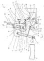
- the contact roller 4 is mounted in a bearing assembly 7, which is designed as a pendulum and in turn is suspended in the winder 1 via a relative to the machine frame set, schematically indicated in the figure swivel bearing 8. It has a pivoting frame 9, in which a shaft 10 of the contact roller 4 is mounted.
- the shaft 10 is optimally arranged so that it is located vertically below the Verschwenklager 8 when the bearing assembly 7 freely suspended in rest position; then the shaft 10 and the contact roller 4 are at their lowest point, which position corresponds to the desired position of the contact roller 4.
- the bearing arrangement 7 can be mounted, for example, via an axis 11 parallel to the shaft 10 in the swivel bearing 8. In any case, the bearing assembly 7 suspended so that the possible pivotal movement of the contact roller 4 about its desired position on the winding 6 to and from in the way (or on the winding core bearing 15 to and away from him, see below). Further, a sensor 13 for detecting the actual position of the contact roller 4 is connected to the swing frame 9.
- the contact roller 4 is floating around a target position in the direction of the winding core bearing 15 and away from it.
- the winding 6 is mounted with its winding core 5 in a winding core bearing 15 of a carrier assembly 16.
- the carrier assembly 16 preferably has a pair of support arms 17 for the winding core 5, which is pivotable about a Tragarmachse 18.
- the shaft 10 of the contact roller 4, the axis 11, the orientation of the hub bearing 15 and the Tragarmachse 18 are parallel.
- a device 21 for changing the relative position of the contact roller 4 and the winding core bearing 15 has a drive, here a hydraulic cylinder assembly 19 which is articulated on the one hand on schematically indicated machine frame M and on the other hand connected to the support arm 17.
- the support arm pair 17 can be pivoted, that is, the winding core bearing 15 is moved away from the contact roller 4 or pivoted away.
- means 23 are provided for generating a lasting during the winding application pressure between the winding 6 and the contact roller 4 having a preferably pneumatic cylinder assembly 24, which hinged on the one hand on schematically indicated machine frame M and on the other hand connected to the swing frame 9.
- FIG. 1 shows schematically a machine control 30, connected to a control line 31 of the sensor 13, and connected to a Control line 32 for the input of data by an operator or for data exchange with a line control.
- the machine control 30 is connected to a hydraulic unit 33 for the cylinder arrangement 19 and to a pneumatic unit 34 for the cylinder arrangement 24, wherein the hydraulic-pneumatic units 33, 34 in turn via hydraulic and pneumatic lines 35, 36 and 37, 38 with the cylinder arrangements 19 , 24 are connected.
- a motor 40 rotates the winding core 5 in rotation via a toothed belt indicated by the dot-dash line 41, so that the winder 1 can be moved with the so-called central winding.
- a motor 42 is provided which can drive the contact roller 4 for the conventional contact winding.
- a known per se delivery device 45 for hubs 5 is located above the swing frame 9.
- an auxiliary receiving device 46 is provided for freshly wound hubs 5; it has provided on both sides of the contact drum 4 forks 47th
- pneumatic cylinder arrangements can also be provided by the person skilled in the art, or other actuators of any design, as far as they can be actuated by the machine control 30, as described below. It is also conceivable, in place of the support arm pair 17 or the swing frame 12 back and forth slidably provided, etc., provided that then the functionally necessary range of motion is given.
- the necessary operating parameters are entered by the operator via the data line 32, including the information necessary for determining the desired radius of the roll 6.
- this preferably also includes the thickness d of the film to be wound.
- the length I The continuously wound film can be suitably removed via a length sensor, for example, via the number of revolutions of a guide roller 14, or can be continuously input to the controller 30 via the line control.
- the controller 30 calculates, starting from a starting position of the winding core bearing at the beginning of the winding, over the product I * d the current desired radius increase of the coil 6 and the consequent desired distance of the winding core 6 from the contact roller 4 and generates the associated control signal for the hydraulic unit 33.
- the deceleration speed of the winding core bearing 15 is determined independently of the application pressure.
- the machine controller 30 controls the cylinder assembly 24 via the pneumatic unit 34 in such a way that the contact roller 4 exerts the input pressure applied to the reel 6 and thereby keeps in constant contact with the reel 6.
- the winding core bearing 15 continuously moves away from the contact roller 4 with a desired deceleration speed corresponding to the increasing desired radius of the winding 6 that builds up. Its position remains unchanged as long as the desired radius of the developing coil 6 corresponds to the actual radius. Due to the continuous movement of Tragarmcrus 17 results in a highly constant contact pressure, without the known in the prior art disturbances, (i) due to the stepwise displacement of winding 6 and / or contact drum 4 and (ii) due to the regulation of the displacement movement on the basis of the Imprinting inevitably occur.
- the stepwise displacement is particularly disadvantageous that the necessary start / stop accelerations of the winding 6 and contact roller. 4 Inertia forces have the consequence that not only can not be compensated by the control or regulation, but also negatively affect them themselves. A not to be underestimated role also play the friction forces, in particular the static friction. At the beginning of a stepwise movement of the winding 6 and / or contact roller 4, the static friction force is overcome, which often assumes high values depending on the design of the winder, and then drops abruptly to the value of the sliding friction force.
- the minimum allowable apply pressure must be at least the value of the static frictional force, which is too high for certain applications; If a lower application pressure is permitted, it follows that after overcoming the static friction, an undesirable application pressure peak is to be accepted until the regulation has reduced the application pressure to the lower value.
- the pendulum-like design suspension (in contrast to about a linearly displaceable slide) of the contact roller 4 on the swing frame 12 is advantageous: shifts the contact roller from its the desired position addition, created by their weight a restoring force in the direction of the desired position, which helps to overcome the static friction forces that occur after a possibly short stoppage of the displacement movement.
- radius and actual radius of the coil 6 do not match, either by incorrect input of the thickness d, or by changing the thickness d during the production of the film, or by the drift of any other parameter, the floating contact roller 4 due the constant contact pressure by the cylinder assembly 24 of the actual contour of the coil 6 follow easily.
- the machine controller 30 continuously queries via the control line 31 from the actual position of the contact roller 4 and generates a correction for the calculated on the determination of the target radius Abgur nie.
- the Contact roller If the actual radius of the coil 6 is smaller than the calculated nominal radius, for example because the actual thickness of the film 3 is smaller than the value entered by the operator via the control line 32 (or eg drift of the thickness d), the Contact roller from its desired position out against the winding 6 forward, which is detected by the sensor 13. The machine control then adjusts the Abgurissus the actual radius, by slowing them, so that the contact roller 4 displaced over the further increasing actual radius of the coil 6, back to its desired position. Once this is the case, the deceleration rate is increased again.
- the adjustment of the Abrück Malawi stepwise so that is detected after a first Apassungsuze whether the contact roller (4) already moves back into its desired position (they could, for example, also come to rest only outside their desired position), in this case the adjustment has taken place or, if the contact roller (4) has not yet moved back against the desired position, a further adaptation step takes place, and then it is again detected whether the contact roller (4) moves back, and so on, until, until the contact roller (4) actually moves back to its desired position, so the desired correction effect is achieved.
- the above-described control mechanism is repeated several times and without delay, as soon as the contact roller 4 has reached its desired position again.
- corrected the machine control 30 preferably the thickness d, for example by 0.5, 1, 2 or more percent of the input thickness d, so that the calculated target radius corresponds to the actual radius improved and the control leaves the otherwise endless control loop by adjusting the Abschreib nie.
- the machine control recognizes a synchronous to the number of revolutions of the coil 6 pulsating displacement of the position of the contact roller 4.
- a displacement is created by a non-circular winding; a correction in the sense described above by continuous adjustment of Abgur für a is only conditionally meaningful. Therefore, the controller 30 determines the displacement interval of the position of the contact roller 4 given by the pulsation, and the middle of this interval.
- the deceleration rate is then adjusted so that the center of the interval is returned to the desired position of the shaft 10 of the contact roller 4. This correction may be performed by itself or in conjunction with the above-described correction of the deceleration rate (in the case of the drift of a parameter).
- the application pressure of the contact roller 4 can be temporarily increased slightly as the contact roller 4 is pressed by the non-round winding from the target position to the rear of the shift interval. This can counteract an increase in the non-round profile of the coil 6 and the smoothing of the profile can be supported.
- the deceleration rate is adjusted so smoothly in all of the control cases described above that no or only low pressure peaks occur.
- the adjustment may not be larger than the speed-resolving capability of the hydraulic system , Even if then the Abgur Mari temporarily to Standstill should occur, no application pressure peaks occur because the speed change, despite full winding speed as small as possible.
- the adjustment of the deceleration rate is made such that it is changed in a first step by a small amount. If the sensor 13 then detects a return movement of the contact roller 4 against its desired position, it remains with the adaptation made; if not, the deceleration rate is changed by a further step, and so on, until the contact roller 4 moves back towards its desired position.
- This allows the Abschreib horretti very finely adjusted (in terms of a given drive optimal) and worked with the minimum possible speed differences, so that the application pressure remains undisturbed.
- the system can be considered self-optimizing.
- a further optimization can be carried out in a further preferred embodiment in that the Abgur Vietnamese is no longer set to the original value when the contact roller 4 has reached its desired position, but to a value which in turn by a small amount from the original Value is different. If the contact roller 4 has therefore returned to its desired position from behind, the original deceleration speed was too low, and is now increased by one step; if the contact roller 4 has returned to its desired position from the front, the original deceleration speed was too high and is withdrawn by one step.
- the adjusted deceleration speed is reversed such that it is set to a value which is a speed interval below or above the calculated target deceleration speed, such that the desired radius corresponds to the actual radius improved. This can be counteracted above all a systematic error in the calculation of the desired radius.
- the machine controller 30 is thus configured to perform the functions described above and below; Based on the present functional description, the control software can easily be created by the person skilled in the art on the basis of the given, specific design of the winder. This also applies to the necessary parameters, e.g. the size of the steps to adjust the deceleration rate.
- a cross-cutting system not shown for the purpose of relieving the figure, cuts through the material web 3.
- Such cross-cutting systems for winders of the present type are known in the art.
- the support arm pair 17 is pivoted against the tray 2 for finished winding 6 and the finished winding 6 stored there by the machine control 30.
- the Tragarmport 17 is pivoted back to its starting position to wait for the wound winding core 5 and receive it in its hub bearing 15. The winding cycle then starts again.
- the feed device 45 lowers the next winding core 5 (see the double arrow 48 in the figure) and places it in the forks 47 of the auxiliary receiving device 46.
- the cross-cutting system cuts the cut, whereupon, on the one hand mentioned, the Tragarmcru swung away with the finished winding 6, and on the other hand, the new winding core 5 is brought for the Anwicklung with the resting on the contact roller 4 front end of the freshly cut material web 3 in contact.
- the auxiliary receiving device 46 pivots counterclockwise (s. FIG. 1 ) and transfers the wound winding core 5 into the winding core bearing 15 of the now pivoted-back support arm pair 17.
- This process of flying change of the roll per se is also known in the art.
- the winder according to the invention is designed in such a way that that the flying change can be carried out in the known manner.
- the winder 1 according to the invention is to be driven with gap winding, it is sufficient to input the desired gap dimension via the control line 32, whereupon the controller calculates the deceleration speed such that the gap is always maintained.
- the gap is sized so that in case of disturbances e.g. by incorrect specification of the thickness d of the film 3, the gap can not be closed until the desired winding progress (completely wound winding 6). This eliminates the need for light barriers, etc. according to the constructions known in the prior art.
- the inventive method in addition to the Konatktwicklung and the gap winding can be improved.
Landscapes
- Winding Of Webs (AREA)
- Laminated Bodies (AREA)
Applications Claiming Priority (1)
| Application Number | Priority Date | Filing Date | Title |
|---|---|---|---|
| CH15982007 | 2007-10-12 |
Publications (2)
| Publication Number | Publication Date |
|---|---|
| EP2048100A1 true EP2048100A1 (fr) | 2009-04-15 |
| EP2048100B1 EP2048100B1 (fr) | 2009-08-05 |
Family
ID=39277120
Family Applications (1)
| Application Number | Title | Priority Date | Filing Date |
|---|---|---|---|
| EP08166307A Not-in-force EP2048100B1 (fr) | 2007-10-12 | 2008-10-10 | Enrouleur pour une bande de matériau en matériau flexible |
Country Status (4)
| Country | Link |
|---|---|
| US (1) | US7959102B2 (fr) |
| EP (1) | EP2048100B1 (fr) |
| AT (1) | ATE438579T1 (fr) |
| DE (1) | DE502008000067D1 (fr) |
Cited By (2)
| Publication number | Priority date | Publication date | Assignee | Title |
|---|---|---|---|---|
| WO2011103695A1 (fr) | 2010-02-23 | 2011-09-01 | Swiss Winding Inventing Ag | Arbre d'enroulement pour une enrouleuse |
| DE102021110643A1 (de) | 2021-04-26 | 2022-10-27 | Sprick Gmbh Bielefelder Papier- Und Wellpappenwerke & Co. | Polsterwickler und Polsterwickelverfahren |
Families Citing this family (13)
| Publication number | Priority date | Publication date | Assignee | Title |
|---|---|---|---|---|
| AT508289B1 (de) * | 2009-05-22 | 2011-02-15 | Andritz Ag Maschf | Vorrichtung zum kontinuierlichen aufwickeln einer faserstoffbahn |
| US8733686B2 (en) | 2010-10-25 | 2014-05-27 | The Procter & Gamble Company | Alternative apparatus for reducing web feed rate variations induced by parent roll geometry variations |
| US9434572B2 (en) | 2010-10-25 | 2016-09-06 | The Procter & Gamble Company | Alternative method for reducing web feed rate variations induced by parent roll geometry variations |
| US8757535B2 (en) | 2010-10-25 | 2014-06-24 | The Procter & Gamble Company | Method for reducing web feed rate variations induced by parent roll geometry variations |
| US8733685B2 (en) | 2010-10-25 | 2014-05-27 | The Procter & Gamble Company | Apparatus for reducing web feed rate variations induced by parent roll geometry variations |
| US9434573B2 (en) | 2010-10-25 | 2016-09-06 | The Procter & Gamble Company | Alternative method for reducing web feed rate variations induced by parent roll geometry variations |
| US8733687B2 (en) | 2010-10-25 | 2014-05-27 | The Procter & Gamble Company | Alternative apparatus for reducing web feed rate variations induced by parent roll geometry variations |
| US8740130B2 (en) | 2010-10-25 | 2014-06-03 | The Procter & Gamble Company | Alternative method for reducing web feed rate variations induced by parent roll geometry variations |
| CN102874627A (zh) * | 2012-10-12 | 2013-01-16 | 无锡市张泾宇钢机械厂 | 一种钢带收卷机的双铰压臂机构 |
| CN104192605B (zh) * | 2014-08-29 | 2016-08-24 | 山东天阳纸业有限公司 | 卷纸辊加压装置 |
| DE102017108496B4 (de) * | 2017-04-21 | 2023-06-29 | Windmöller & Hölscher Kg | Verfahren und Vorrichtungen sowie System zum Auf- und Abwickeln eines Wickels |
| CN110642049A (zh) * | 2019-09-26 | 2020-01-03 | 仙鹤股份有限公司 | 用于纸张卷绕的防断纸结构 |
| CN113788363B (zh) * | 2021-11-16 | 2022-02-01 | 山东大业股份有限公司 | 一种胎圈钢丝收线张紧装置 |
Citations (7)
| Publication number | Priority date | Publication date | Assignee | Title |
|---|---|---|---|---|
| DE2037979A1 (de) | 1969-07-30 | 1971-02-11 | Nishimura Seisakusho Co. Ltd., Kyoto (Japan) | Wickeleinrichtung |
| DE2214350A1 (de) * | 1972-03-24 | 1973-10-04 | Kampf Maschf Erwin | Aufwickelvorrichtung fuer baender und folien |
| DE2264587A1 (de) * | 1972-03-24 | 1974-05-16 | Kampf Maschf Erwin | Aufwickelvorrichtung fuer baender oder folien |
| DE3308059A1 (de) | 1983-03-08 | 1984-09-20 | Erwin Kampf Gmbh & Co Maschinenfabrik, 5276 Wiehl | Rollenschneid- und wickelmaschine |
| CH678419A5 (fr) | 1989-04-21 | 1991-09-13 | Gottlieb Looser | |
| EP0561128A1 (fr) | 1992-03-18 | 1993-09-22 | Anton Rüegg | Procédé et dispositif destiné à l'enroulement d'un matériau |
| WO2003076320A1 (fr) * | 2002-03-08 | 2003-09-18 | Metso Paper Karlstad Ab | Installation et procede d'enroulement d'une bande de papier et dispositif de commande de la charge de contact |
Family Cites Families (26)
| Publication number | Priority date | Publication date | Assignee | Title |
|---|---|---|---|---|
| US561128A (en) * | 1896-06-02 | Trolley-switch | ||
| US17277A (en) * | 1857-05-12 | Improvement in harvesters | ||
| US666014A (en) * | 1900-01-27 | 1901-01-15 | Arthur M Kauffman | Wagon-jack. |
| US686885A (en) * | 1901-08-31 | 1901-11-19 | William Schimper & Company | Chatelaine. |
| US1099750A (en) * | 1913-05-21 | 1914-06-09 | Mary Haines Jayne | Collar fastener and support. |
| US1167256A (en) * | 1915-05-18 | 1916-01-04 | Charlotte Bergman | Vibrator. |
| US2037979A (en) * | 1935-04-04 | 1936-04-21 | Int Harvester Co | Disk removing tool for cream separators |
| US2214350A (en) * | 1939-02-20 | 1940-09-10 | Grant John | Well cleaning tool |
| US2264587A (en) * | 1940-01-09 | 1941-12-02 | Ibm | Character displaying control apparatus |
| US3035521A (en) * | 1955-06-30 | 1962-05-22 | Stewart Warner Corp | Hydraulically timed electrical switch |
| US3076320A (en) * | 1960-01-04 | 1963-02-05 | Conradi Henrik | Air cooling system for cold storage rooms |
| GB1082188A (en) * | 1965-03-31 | 1967-09-06 | Shell Int Research | Process for the separation of a mixture containing hydrocarbons |
| GB1099750A (en) | 1966-07-29 | 1968-01-17 | Hobbs Mfg Company | Density control apparatus for web winding machine |
| SE331333B (fr) * | 1969-01-14 | 1970-12-21 | K Boij | |
| US3736696A (en) * | 1971-12-13 | 1973-06-05 | Mattel Inc | Construction toy utilizing real or simulated household tools and simulating a real or imagined living thing |
| US4191341A (en) * | 1979-04-03 | 1980-03-04 | Gottlieb Looser | Winding apparatus and method |
| DE3335713C2 (de) | 1983-10-01 | 1986-09-04 | Reifenhäuser GmbH & Co Maschinenfabrik, 5210 Troisdorf | Vorrichtung zum Aufwickeln von Folienbahnen |
| DE3627463A1 (de) | 1986-08-13 | 1988-02-18 | Smg Stahlkontor Maschinenbau G | Vorrichtung zum regeln bzw. steuern einer kontaktwalze |
| DE3736696A1 (de) | 1987-03-09 | 1988-09-29 | Windmoeller & Hoelscher | Verfahren zur regelung des anpressdruckes zwischen einer kontaktwalze und einer von dieser angetriebenen wickelrolle |
| DE8808823U1 (de) * | 1988-07-08 | 1988-08-25 | Sulzer-Escher Wyss Gmbh, 88212 Ravensburg | Vorrichtung für das kontinuierliche Aufwickeln einer Bahn aus blattförmigem Material, insbesondere einer Papierbahn |
| CH686885A5 (de) | 1993-11-26 | 1996-07-31 | Anton Ruegg | Verfahren und Vorrichtung zum Aufwickeln von bahnfoermigem Material. |
| US6325232B1 (en) * | 1996-07-19 | 2001-12-04 | Effem Gmbh | Process for producing a filled container and filled container |
| ATE234254T1 (de) | 1997-05-16 | 2003-03-15 | Voith Paper Patent Gmbh | Verfahren und wickelmaschine zum kontinuierlichen aufwickeln einer materialbahn |
| US6834824B1 (en) * | 1999-03-16 | 2004-12-28 | Black Clawson Converting Machinery, Inc. | Continuous winder and method of winding slit rolls of large diameter on small diameter cores |
| DE10030199A1 (de) | 2000-06-20 | 2002-01-03 | Voith Paper Patent Gmbh | Verfahren und Wickelmaschine zum kontinuierlichen Aufwickeln einer Materialbahn |
| DE10202687B4 (de) | 2001-10-24 | 2005-09-08 | Windmöller & Hölscher Kg | Vorrichtung zum kontinuierlichen Aufwickeln von Bahnen |
-
2008
- 2008-10-09 US US12/287,484 patent/US7959102B2/en not_active Expired - Fee Related
- 2008-10-10 EP EP08166307A patent/EP2048100B1/fr not_active Not-in-force
- 2008-10-10 DE DE502008000067T patent/DE502008000067D1/de active Active
- 2008-10-10 AT AT08166307T patent/ATE438579T1/de not_active IP Right Cessation
Patent Citations (7)
| Publication number | Priority date | Publication date | Assignee | Title |
|---|---|---|---|---|
| DE2037979A1 (de) | 1969-07-30 | 1971-02-11 | Nishimura Seisakusho Co. Ltd., Kyoto (Japan) | Wickeleinrichtung |
| DE2214350A1 (de) * | 1972-03-24 | 1973-10-04 | Kampf Maschf Erwin | Aufwickelvorrichtung fuer baender und folien |
| DE2264587A1 (de) * | 1972-03-24 | 1974-05-16 | Kampf Maschf Erwin | Aufwickelvorrichtung fuer baender oder folien |
| DE3308059A1 (de) | 1983-03-08 | 1984-09-20 | Erwin Kampf Gmbh & Co Maschinenfabrik, 5276 Wiehl | Rollenschneid- und wickelmaschine |
| CH678419A5 (fr) | 1989-04-21 | 1991-09-13 | Gottlieb Looser | |
| EP0561128A1 (fr) | 1992-03-18 | 1993-09-22 | Anton Rüegg | Procédé et dispositif destiné à l'enroulement d'un matériau |
| WO2003076320A1 (fr) * | 2002-03-08 | 2003-09-18 | Metso Paper Karlstad Ab | Installation et procede d'enroulement d'une bande de papier et dispositif de commande de la charge de contact |
Cited By (3)
| Publication number | Priority date | Publication date | Assignee | Title |
|---|---|---|---|---|
| WO2011103695A1 (fr) | 2010-02-23 | 2011-09-01 | Swiss Winding Inventing Ag | Arbre d'enroulement pour une enrouleuse |
| WO2011103696A1 (fr) | 2010-02-23 | 2011-09-01 | Swiss Winding Inventing Ag | Manchon d'enroulement pour une bande continue de film en plastique |
| DE102021110643A1 (de) | 2021-04-26 | 2022-10-27 | Sprick Gmbh Bielefelder Papier- Und Wellpappenwerke & Co. | Polsterwickler und Polsterwickelverfahren |
Also Published As
| Publication number | Publication date |
|---|---|
| EP2048100B1 (fr) | 2009-08-05 |
| ATE438579T1 (de) | 2009-08-15 |
| DE502008000067D1 (de) | 2009-09-17 |
| US20090101746A1 (en) | 2009-04-23 |
| US7959102B2 (en) | 2011-06-14 |
Similar Documents
| Publication | Publication Date | Title |
|---|---|---|
| EP2048100B1 (fr) | Enrouleur pour une bande de matériau en matériau flexible | |
| DE69305274T2 (de) | Maschine und Verfahren zur Fertigung von kernlosen Rollen von Bahnmaterial | |
| EP0941955B1 (fr) | Méthode et dispositif pour continuellement enrouler une bande de matériau | |
| DE60214304T2 (de) | Vorrichtung zur laufenden Spannungskontrolle einer Papierbahn für Rotationsdruckmaschine | |
| EP2815857B1 (fr) | Ciseaux | |
| EP0799337B1 (fr) | Dispositif d'enroulement | |
| EP1314668B1 (fr) | Dispositif pour transporter materiau en bande | |
| EP0912435A1 (fr) | Procede de bobinage continu d'une bande de materiau et bobineuse correspondante | |
| DE2644298A1 (de) | Vorrichtung zum anschliessen einer bobine aus papier oder einem anderen material an eine andere bobine | |
| DE2335294A1 (de) | Wickelspannung-steuersystem | |
| DE2905988A1 (de) | Pneumatische bogenzufuehrvorrichtung | |
| DE69510848T2 (de) | Übertragungsvorrichtung für Klebstoff in einer Filterzigarettenherstellungsmaschine | |
| EP2782858B1 (fr) | Enrouleur pour une bande de matière continue | |
| EP0893252B1 (fr) | Dispositif pour ajuster la tension de la bande après un dispositif refroidisseur dans une machine à imprimer | |
| DE3702702C2 (fr) | ||
| EP0160165B1 (fr) | Procédé et dispositif pour la formation d'un enroulement d'ouate | |
| EP1647509B1 (fr) | Dispositif de raccordement des extrémités de deux bandes de matériau | |
| DE69814853T2 (de) | Verfahren sowie Vorrichtung zum Bewegen des Kreismessers einer Maschine zum Schneiden von Papierrollen oder dergleichen | |
| EP3424854B1 (fr) | Fourniture de matériau de feuille intermédiaire en forme de bande à une zone de coupe | |
| DE202014103124U1 (de) | Slitter zum Schneiden eines Cordbandes | |
| DE602005001693T2 (de) | Aufwickelvorrichtung mit zwei antriebsrollen für durchlaufaufwickelmaschine mit gesteuerter anlegelast der antriebsrollen | |
| EP2808281B1 (fr) | Dispositif d'épissurage pour l'épissurage de cordages | |
| CH662547A5 (en) | Device for winding and unwinding an imbricated stream of flat articles, such as paper sheets | |
| EP2965896B1 (fr) | Découpeur d'une bande de corde | |
| DE2035291C3 (de) | Hydrostatischer Antrieb mit Bahnspannungsregelung für eine als Doppeltragwalzenroller ausgebildete schnelaufende Umrollmaschine |
Legal Events
| Date | Code | Title | Description |
|---|---|---|---|
| GRAP | Despatch of communication of intention to grant a patent |
Free format text: ORIGINAL CODE: EPIDOSNIGR1 |
|
| PUAI | Public reference made under article 153(3) epc to a published international application that has entered the european phase |
Free format text: ORIGINAL CODE: 0009012 |
|
| 17P | Request for examination filed |
Effective date: 20081014 |
|
| AK | Designated contracting states |
Kind code of ref document: A1 Designated state(s): AT BE BG CH CY CZ DE DK EE ES FI FR GB GR HR HU IE IS IT LI LT LU LV MC MT NL NO PL PT RO SE SI SK TR |
|
| AX | Request for extension of the european patent |
Extension state: AL BA MK RS |
|
| GRAS | Grant fee paid |
Free format text: ORIGINAL CODE: EPIDOSNIGR3 |
|
| GRAA | (expected) grant |
Free format text: ORIGINAL CODE: 0009210 |
|
| AK | Designated contracting states |
Kind code of ref document: B1 Designated state(s): AT BE BG CH CY CZ DE DK EE ES FI FR GB GR HR HU IE IS IT LI LT LU LV MC MT NL NO PL PT RO SE SI SK TR |
|
| REG | Reference to a national code |
Ref country code: GB Ref legal event code: FG4D Free format text: NOT ENGLISH |
|
| REG | Reference to a national code |
Ref country code: CH Ref legal event code: EP |
|
| REG | Reference to a national code |
Ref country code: IE Ref legal event code: FG4D |
|
| REF | Corresponds to: |
Ref document number: 502008000067 Country of ref document: DE Date of ref document: 20090917 Kind code of ref document: P |
|
| AKX | Designation fees paid |
Designated state(s): AT BE BG CH CY CZ DE DK EE ES FI FR GB GR HR HU IE IS IT LI LT LU LV MC MT NL NO PL PT RO SE SI SK TR |
|
| LTIE | Lt: invalidation of european patent or patent extension |
Effective date: 20090805 |
|
| PG25 | Lapsed in a contracting state [announced via postgrant information from national office to epo] |
Ref country code: NO Free format text: LAPSE BECAUSE OF FAILURE TO SUBMIT A TRANSLATION OF THE DESCRIPTION OR TO PAY THE FEE WITHIN THE PRESCRIBED TIME-LIMIT Effective date: 20091105 Ref country code: FI Free format text: LAPSE BECAUSE OF FAILURE TO SUBMIT A TRANSLATION OF THE DESCRIPTION OR TO PAY THE FEE WITHIN THE PRESCRIBED TIME-LIMIT Effective date: 20090805 Ref country code: ES Free format text: LAPSE BECAUSE OF FAILURE TO SUBMIT A TRANSLATION OF THE DESCRIPTION OR TO PAY THE FEE WITHIN THE PRESCRIBED TIME-LIMIT Effective date: 20091116 Ref country code: SE Free format text: LAPSE BECAUSE OF FAILURE TO SUBMIT A TRANSLATION OF THE DESCRIPTION OR TO PAY THE FEE WITHIN THE PRESCRIBED TIME-LIMIT Effective date: 20090805 Ref country code: IS Free format text: LAPSE BECAUSE OF FAILURE TO SUBMIT A TRANSLATION OF THE DESCRIPTION OR TO PAY THE FEE WITHIN THE PRESCRIBED TIME-LIMIT Effective date: 20091205 Ref country code: LT Free format text: LAPSE BECAUSE OF FAILURE TO SUBMIT A TRANSLATION OF THE DESCRIPTION OR TO PAY THE FEE WITHIN THE PRESCRIBED TIME-LIMIT Effective date: 20090805 |
|
| NLV1 | Nl: lapsed or annulled due to failure to fulfill the requirements of art. 29p and 29m of the patents act | ||
| REG | Reference to a national code |
Ref country code: CH Ref legal event code: NV Representative=s name: STUMP UND PARTNER PATENTANWAELTE AG |
|
| PG25 | Lapsed in a contracting state [announced via postgrant information from national office to epo] |
Ref country code: LV Free format text: LAPSE BECAUSE OF FAILURE TO SUBMIT A TRANSLATION OF THE DESCRIPTION OR TO PAY THE FEE WITHIN THE PRESCRIBED TIME-LIMIT Effective date: 20090805 Ref country code: PL Free format text: LAPSE BECAUSE OF FAILURE TO SUBMIT A TRANSLATION OF THE DESCRIPTION OR TO PAY THE FEE WITHIN THE PRESCRIBED TIME-LIMIT Effective date: 20090805 Ref country code: NL Free format text: LAPSE BECAUSE OF FAILURE TO SUBMIT A TRANSLATION OF THE DESCRIPTION OR TO PAY THE FEE WITHIN THE PRESCRIBED TIME-LIMIT Effective date: 20090805 Ref country code: SI Free format text: LAPSE BECAUSE OF FAILURE TO SUBMIT A TRANSLATION OF THE DESCRIPTION OR TO PAY THE FEE WITHIN THE PRESCRIBED TIME-LIMIT Effective date: 20090805 Ref country code: HR Free format text: LAPSE BECAUSE OF FAILURE TO SUBMIT A TRANSLATION OF THE DESCRIPTION OR TO PAY THE FEE WITHIN THE PRESCRIBED TIME-LIMIT Effective date: 20090805 |
|
| REG | Reference to a national code |
Ref country code: IE Ref legal event code: FD4D |
|
| PG25 | Lapsed in a contracting state [announced via postgrant information from national office to epo] |
Ref country code: BG Free format text: LAPSE BECAUSE OF FAILURE TO SUBMIT A TRANSLATION OF THE DESCRIPTION OR TO PAY THE FEE WITHIN THE PRESCRIBED TIME-LIMIT Effective date: 20091105 |
|
| PG25 | Lapsed in a contracting state [announced via postgrant information from national office to epo] |
Ref country code: CZ Free format text: LAPSE BECAUSE OF FAILURE TO SUBMIT A TRANSLATION OF THE DESCRIPTION OR TO PAY THE FEE WITHIN THE PRESCRIBED TIME-LIMIT Effective date: 20090805 Ref country code: DK Free format text: LAPSE BECAUSE OF FAILURE TO SUBMIT A TRANSLATION OF THE DESCRIPTION OR TO PAY THE FEE WITHIN THE PRESCRIBED TIME-LIMIT Effective date: 20090805 Ref country code: RO Free format text: LAPSE BECAUSE OF FAILURE TO SUBMIT A TRANSLATION OF THE DESCRIPTION OR TO PAY THE FEE WITHIN THE PRESCRIBED TIME-LIMIT Effective date: 20090805 Ref country code: IE Free format text: LAPSE BECAUSE OF FAILURE TO SUBMIT A TRANSLATION OF THE DESCRIPTION OR TO PAY THE FEE WITHIN THE PRESCRIBED TIME-LIMIT Effective date: 20090805 Ref country code: EE Free format text: LAPSE BECAUSE OF FAILURE TO SUBMIT A TRANSLATION OF THE DESCRIPTION OR TO PAY THE FEE WITHIN THE PRESCRIBED TIME-LIMIT Effective date: 20090805 |
|
| PG25 | Lapsed in a contracting state [announced via postgrant information from national office to epo] |
Ref country code: SK Free format text: LAPSE BECAUSE OF FAILURE TO SUBMIT A TRANSLATION OF THE DESCRIPTION OR TO PAY THE FEE WITHIN THE PRESCRIBED TIME-LIMIT Effective date: 20090805 Ref country code: MC Free format text: LAPSE BECAUSE OF NON-PAYMENT OF DUE FEES Effective date: 20091031 |
|
| PLBE | No opposition filed within time limit |
Free format text: ORIGINAL CODE: 0009261 |
|
| STAA | Information on the status of an ep patent application or granted ep patent |
Free format text: STATUS: NO OPPOSITION FILED WITHIN TIME LIMIT |
|
| 26N | No opposition filed |
Effective date: 20100507 |
|
| REG | Reference to a national code |
Ref country code: FR Ref legal event code: ST Effective date: 20100630 |
|
| PG25 | Lapsed in a contracting state [announced via postgrant information from national office to epo] |
Ref country code: FR Free format text: LAPSE BECAUSE OF NON-PAYMENT OF DUE FEES Effective date: 20091102 |
|
| REG | Reference to a national code |
Ref country code: FR Ref legal event code: RN |
|
| PG25 | Lapsed in a contracting state [announced via postgrant information from national office to epo] |
Ref country code: GR Free format text: LAPSE BECAUSE OF FAILURE TO SUBMIT A TRANSLATION OF THE DESCRIPTION OR TO PAY THE FEE WITHIN THE PRESCRIBED TIME-LIMIT Effective date: 20091106 |
|
| REG | Reference to a national code |
Ref country code: FR Ref legal event code: FC |
|
| PGRI | Patent reinstated in contracting state [announced from national office to epo] |
Ref country code: FR Effective date: 20101026 |
|
| PG25 | Lapsed in a contracting state [announced via postgrant information from national office to epo] |
Ref country code: IT Free format text: LAPSE BECAUSE OF FAILURE TO SUBMIT A TRANSLATION OF THE DESCRIPTION OR TO PAY THE FEE WITHIN THE PRESCRIBED TIME-LIMIT Effective date: 20090805 |
|
| BERE | Be: lapsed |
Owner name: SWISS WINDING PERFORMANCE A.G. Effective date: 20101031 |
|
| PG25 | Lapsed in a contracting state [announced via postgrant information from national office to epo] |
Ref country code: HU Free format text: LAPSE BECAUSE OF FAILURE TO SUBMIT A TRANSLATION OF THE DESCRIPTION OR TO PAY THE FEE WITHIN THE PRESCRIBED TIME-LIMIT Effective date: 20100206 |
|
| PG25 | Lapsed in a contracting state [announced via postgrant information from national office to epo] |
Ref country code: BE Free format text: LAPSE BECAUSE OF NON-PAYMENT OF DUE FEES Effective date: 20101031 Ref country code: TR Free format text: LAPSE BECAUSE OF FAILURE TO SUBMIT A TRANSLATION OF THE DESCRIPTION OR TO PAY THE FEE WITHIN THE PRESCRIBED TIME-LIMIT Effective date: 20090805 |
|
| PG25 | Lapsed in a contracting state [announced via postgrant information from national office to epo] |
Ref country code: MT Free format text: LAPSE BECAUSE OF FAILURE TO SUBMIT A TRANSLATION OF THE DESCRIPTION OR TO PAY THE FEE WITHIN THE PRESCRIBED TIME-LIMIT Effective date: 20090805 |
|
| PG25 | Lapsed in a contracting state [announced via postgrant information from national office to epo] |
Ref country code: CY Free format text: LAPSE BECAUSE OF FAILURE TO SUBMIT A TRANSLATION OF THE DESCRIPTION OR TO PAY THE FEE WITHIN THE PRESCRIBED TIME-LIMIT Effective date: 20090805 |
|
| PG25 | Lapsed in a contracting state [announced via postgrant information from national office to epo] |
Ref country code: PT Free format text: LAPSE BECAUSE OF FAILURE TO SUBMIT A TRANSLATION OF THE DESCRIPTION OR TO PAY THE FEE WITHIN THE PRESCRIBED TIME-LIMIT Effective date: 20100105 |
|
| REG | Reference to a national code |
Ref country code: CH Ref legal event code: PCAR Free format text: NEW ADDRESS: ZIMMERGASSE 16, 8008 ZUERICH (CH) |
|
| REG | Reference to a national code |
Ref country code: FR Ref legal event code: PLFP Year of fee payment: 7 |
|
| PG25 | Lapsed in a contracting state [announced via postgrant information from national office to epo] |
Ref country code: LU Free format text: LAPSE BECAUSE OF NON-PAYMENT OF DUE FEES Effective date: 20141010 |
|
| PGFP | Annual fee paid to national office [announced via postgrant information from national office to epo] |
Ref country code: LU Payment date: 20150507 Year of fee payment: 7 |
|
| PGFP | Annual fee paid to national office [announced via postgrant information from national office to epo] |
Ref country code: DE Payment date: 20150430 Year of fee payment: 7 Ref country code: CH Payment date: 20150424 Year of fee payment: 7 Ref country code: GB Payment date: 20150429 Year of fee payment: 7 |
|
| PGFP | Annual fee paid to national office [announced via postgrant information from national office to epo] |
Ref country code: FR Payment date: 20150429 Year of fee payment: 7 Ref country code: AT Payment date: 20150430 Year of fee payment: 7 |
|
| REG | Reference to a national code |
Ref country code: DE Ref legal event code: R119 Ref document number: 502008000067 Country of ref document: DE |
|
| REG | Reference to a national code |
Ref country code: CH Ref legal event code: PL |
|
| REG | Reference to a national code |
Ref country code: AT Ref legal event code: MM01 Ref document number: 438579 Country of ref document: AT Kind code of ref document: T Effective date: 20151010 |
|
| GBPC | Gb: european patent ceased through non-payment of renewal fee |
Effective date: 20151010 |
|
| PG25 | Lapsed in a contracting state [announced via postgrant information from national office to epo] |
Ref country code: GB Free format text: LAPSE BECAUSE OF NON-PAYMENT OF DUE FEES Effective date: 20151010 Ref country code: DE Free format text: LAPSE BECAUSE OF NON-PAYMENT OF DUE FEES Effective date: 20160503 Ref country code: LI Free format text: LAPSE BECAUSE OF NON-PAYMENT OF DUE FEES Effective date: 20151031 Ref country code: CH Free format text: LAPSE BECAUSE OF NON-PAYMENT OF DUE FEES Effective date: 20151031 Ref country code: AT Free format text: THE PATENT HAS BEEN ANNULLED BY A DECISION OF A NATIONAL AUTHORITY Effective date: 20091010 |
|
| REG | Reference to a national code |
Ref country code: FR Ref legal event code: ST Effective date: 20160630 |
|
| PG25 | Lapsed in a contracting state [announced via postgrant information from national office to epo] |
Ref country code: FR Free format text: LAPSE BECAUSE OF NON-PAYMENT OF DUE FEES Effective date: 20151102 Ref country code: AT Free format text: THE PATENT HAS BEEN ANNULLED BY A DECISION OF A NATIONAL AUTHORITY Effective date: 20151010 |
|
| PG25 | Lapsed in a contracting state [announced via postgrant information from national office to epo] |
Ref country code: LU Free format text: LAPSE BECAUSE OF NON-PAYMENT OF DUE FEES Effective date: 20151010 |