EP2048310A2 - Charnière de porte de véhicule automobile - Google Patents
Charnière de porte de véhicule automobile Download PDFInfo
- Publication number
- EP2048310A2 EP2048310A2 EP08016431A EP08016431A EP2048310A2 EP 2048310 A2 EP2048310 A2 EP 2048310A2 EP 08016431 A EP08016431 A EP 08016431A EP 08016431 A EP08016431 A EP 08016431A EP 2048310 A2 EP2048310 A2 EP 2048310A2
- Authority
- EP
- European Patent Office
- Prior art keywords
- vehicle door
- motor vehicle
- door hinge
- hinge according
- control unit
- Prior art date
- Legal status (The legal status is an assumption and is not a legal conclusion. Google has not performed a legal analysis and makes no representation as to the accuracy of the status listed.)
- Withdrawn
Links
- 230000008878 coupling Effects 0.000 claims abstract description 44
- 238000010168 coupling process Methods 0.000 claims abstract description 44
- 238000005859 coupling reaction Methods 0.000 claims abstract description 44
- 230000005540 biological transmission Effects 0.000 claims abstract description 30
- 230000006835 compression Effects 0.000 claims description 7
- 238000007906 compression Methods 0.000 claims description 7
- 230000008859 change Effects 0.000 claims description 6
- 238000006073 displacement reaction Methods 0.000 claims description 5
- 238000000926 separation method Methods 0.000 abstract description 4
- 241000446313 Lamella Species 0.000 abstract 1
- 230000000295 complement effect Effects 0.000 description 4
- 230000008901 benefit Effects 0.000 description 2
- 230000001419 dependent effect Effects 0.000 description 2
- 238000011161 development Methods 0.000 description 2
- 230000018109 developmental process Effects 0.000 description 2
- 238000004519 manufacturing process Methods 0.000 description 2
- 238000006243 chemical reaction Methods 0.000 description 1
- 230000007423 decrease Effects 0.000 description 1
- 230000000694 effects Effects 0.000 description 1
- 210000003746 feather Anatomy 0.000 description 1
- 238000012423 maintenance Methods 0.000 description 1
- 230000036316 preload Effects 0.000 description 1
- 230000009467 reduction Effects 0.000 description 1
- 230000007704 transition Effects 0.000 description 1
Images



Classifications
-
- E—FIXED CONSTRUCTIONS
- E05—LOCKS; KEYS; WINDOW OR DOOR FITTINGS; SAFES
- E05D—HINGES OR SUSPENSION DEVICES FOR DOORS, WINDOWS OR WINGS
- E05D11/00—Additional features or accessories of hinges
- E05D11/10—Devices for preventing movement between relatively-movable hinge parts
- E05D11/1028—Devices for preventing movement between relatively-movable hinge parts for maintaining the hinge in two or more positions, e.g. intermediate or fully open
- E05D11/1078—Devices for preventing movement between relatively-movable hinge parts for maintaining the hinge in two or more positions, e.g. intermediate or fully open the maintaining means acting parallel to the pivot
- E05D11/1085—Devices for preventing movement between relatively-movable hinge parts for maintaining the hinge in two or more positions, e.g. intermediate or fully open the maintaining means acting parallel to the pivot specially adapted for vehicles
-
- E—FIXED CONSTRUCTIONS
- E05—LOCKS; KEYS; WINDOW OR DOOR FITTINGS; SAFES
- E05D—HINGES OR SUSPENSION DEVICES FOR DOORS, WINDOWS OR WINGS
- E05D11/00—Additional features or accessories of hinges
- E05D11/08—Friction devices between relatively-movable hinge parts
- E05D11/087—Friction devices between relatively-movable hinge parts with substantially axial friction, e.g. friction disks
-
- E—FIXED CONSTRUCTIONS
- E05—LOCKS; KEYS; WINDOW OR DOOR FITTINGS; SAFES
- E05D—HINGES OR SUSPENSION DEVICES FOR DOORS, WINDOWS OR WINGS
- E05D11/00—Additional features or accessories of hinges
- E05D11/08—Friction devices between relatively-movable hinge parts
- E05D2011/088—Friction devices between relatively-movable hinge parts with automatic disengagement
-
- E—FIXED CONSTRUCTIONS
- E05—LOCKS; KEYS; WINDOW OR DOOR FITTINGS; SAFES
- E05Y—INDEXING SCHEME ASSOCIATED WITH SUBCLASSES E05D AND E05F, RELATING TO CONSTRUCTION ELEMENTS, ELECTRIC CONTROL, POWER SUPPLY, POWER SIGNAL OR TRANSMISSION, USER INTERFACES, MOUNTING OR COUPLING, DETAILS, ACCESSORIES, AUXILIARY OPERATIONS NOT OTHERWISE PROVIDED FOR, APPLICATION THEREOF
- E05Y2201/00—Constructional elements; Accessories therefor
- E05Y2201/20—Brakes; Disengaging means; Holders; Stops; Valves; Accessories therefor
- E05Y2201/21—Brakes
-
- E—FIXED CONSTRUCTIONS
- E05—LOCKS; KEYS; WINDOW OR DOOR FITTINGS; SAFES
- E05Y—INDEXING SCHEME ASSOCIATED WITH SUBCLASSES E05D AND E05F, RELATING TO CONSTRUCTION ELEMENTS, ELECTRIC CONTROL, POWER SUPPLY, POWER SIGNAL OR TRANSMISSION, USER INTERFACES, MOUNTING OR COUPLING, DETAILS, ACCESSORIES, AUXILIARY OPERATIONS NOT OTHERWISE PROVIDED FOR, APPLICATION THEREOF
- E05Y2900/00—Application of doors, windows, wings or fittings thereof
- E05Y2900/50—Application of doors, windows, wings or fittings thereof for vehicles
- E05Y2900/53—Type of wing
- E05Y2900/531—Doors
Definitions
- motor vehicle door hinges that are used to connect a vehicle door to a vehicle body.
- a fundamental problem with the connection of the vehicle door to the vehicle body is to lock the vehicle door in the set by a user opening angle relative to the vehicle body, so that the vehicle door is protected against accidental closing or swinging.
- Known motor vehicle door hinges usually provide only two or three fixed opening angle, in which the vehicle door is secured against accidental pivoting. There is therefore a need for motor vehicle door hinges in which the vehicle door is secured against further pivoting in any, adjustable by the user opening angle of the door.
- a motor vehicle door hinge of the type mentioned, which is substantially infinitely lockable, is, for example.
- the points from the EP 1144 786 B1 known motor vehicle door hinge the disadvantage that the control unit is designed very complex, which has high production costs.
- the invention has for its object to provide a motor vehicle door hinge, in which the switching between the disconnected position and the coupling position of the disk set is achieved reliably in a simple manner.
- Characteristic of the motor vehicle door hinge according to the invention is the use of a transmission unit which converts a pivoting movement of the door bracket into a rotational movement of the control unit.
- the control unit according to the invention is designed such that the centrifugal forces acting on the control unit during rotation causes the locking unit to be switched over from the coupling position into the disconnected position.
- the gear unit serves to implement already a small pivoting movement of the vehicle door connected to the door console opposite the column connected to the vehicle body console in a rotation of the control unit, which is sufficient that the centrifugal forces acting causes a switching of the locking unit from the coupling position to the release position ,
- a user can conveniently pivot the vehicle door with a force that is considerably reduced in relation to the coupling position.
- the force acting on the disk set is such that the vehicle door is secured against unintentional closing or striking, for example, as a result of an inclination of the vehicle or acting on the vehicle door wind load.
- the arrangement of the gear unit on the motor vehicle door hinge is basically arbitrary. According to a development of the invention, however, a drive shaft of the gear unit is arranged on the door bracket and / or column console such that a pivoting movement of the door bracket causes a rotation of the drive shaft.
- This embodiment of the invention allows a substantially free design of the gear unit in dependence on the required gear ratios. Prerequisite for the operation is merely that a drive shaft of the transmission unit is so connected to the motor vehicle door hinge, that a pivoting movement of the door bracket causes a drive of the gear unit, namely a rotation of the drive shaft.
- the arrangement of the gear unit on the motor vehicle door hinge can be chosen freely according to the design specifications. According to a particularly advantageous embodiment of the invention, however, the gear unit is arranged parallel to the pivot axis of the door bracket and column console.
- This embodiment of the invention in which the pivot axis and the drive shaft axis are not aligned, already makes it possible to design the transmission of the pivoting movement from the pivot axis to the drive shaft of the transmission unit such that there already takes place a translation of the pivoting movement. This translation allows the transmission unit extremely small in size to achieve the final required transmission ratio.
- the drive shaft on a gear formed with a toothed ring gear cantilever of the door bracket engaged gear.
- This embodiment of the invention makes it possible to achieve a translation of the pivoting movement on the gear unit without significant structural changes of the door console and the column console of the motor vehicle door hinge.
- this embodiment of the invention while the already existing distance between the column bracket and the door bracket can be used for translation, so that the additional space for the transmission unit can be reduced in a complementary manner.
- this embodiment of the invention has the advantage that the transmission of the pivoting movement to the gear unit is particularly low maintenance and specializedsunan courses, which increases the reliability of the motor vehicle door hinge in a complementary manner.
- the design of the gear unit to achieve the required translation can in principle be done in any way, with all conventional types can be used. According to a particularly advantageous embodiment of the invention, however, the gear unit is designed as a planetary gear. A correspondingly designed gear unit has the advantage that it can be made extremely compact and has the required for the rotation of the control unit translation.
- the choice of the transmission ratio of the transmission unit can be freely selected according to the design specifications and the choice and design of the control unit, the locking unit, or the entire motor vehicle door hinge.
- the gear unit has a transmission ratio greater than 1: 120, preferably greater than 1: 160, more preferably greater than 1: 200. These ratios are characterized in particular by the fact that they allow the possibility of producing a particularly small gear unit, while ensuring the necessary for the functioning of the motor vehicle door hinge centrifugal forces.
- the arrangement of the locking unit on the motor vehicle door hinge can basically take place in any way, provided that it is ensured that as a result of a pivoting movement of the vehicle door relative to the vehicle body, a relative movement of the inner disk relative to the outer disk of the disk set is achieved.
- the inner disks of the disk set of the locking unit are arranged rotationally fixed on a transmission output shaft of the gear unit and the outer disks are arranged against rotation on a housing of the arrester, wherein the housing itself is arranged rotationally relative to the column console.
- the inner disks of the disk set are arranged on the transmission output shaft such that an anti-rotation is provided. This can be achieved, for example, by a corresponding design of the connection region of the transmission output shaft with the inner disk.
- the arranged in alternation with the inner disks outer disks are in turn arranged against rotation in a housing of the arrester, which in turn is arranged rotationally relative to the column console, so that they remain in a pivotal movement of the vehicle door relative to the column console in position.
- the inner disks are twisted against the outer disks.
- the condition of the disk pack, d. H. in the disconnected position or the coupling position thereby determines the resistance that a user feels when pivoting the vehicle door relative to the vehicle body. This is u. a. also dependent on the number of slats used and the pressure acting on the slat pack.
- the switchover is effected by an adjustment of the pressure element, wherein the pressure acting on the plate pack pressure is changed.
- This embodiment of the invention makes it possible, in a very simple manner, to switch the disk set between the states required for the functioning of the motor vehicle door hinge, namely the disconnected position and the coupling position.
- the design of the printing element is basically freely selectable.
- the pressure element is designed as a parallel to the pivot axis axially displaceable slider. Depending on the position of the slider, the pressure acting on the disk pack is determined.
- the axial displaceability ensures a high degree of functional reliability, wherein an uneven loading of the disk pack is prevented by the slider particularly reliable because tilting of the slider and thus a non-uniform contact with the disk set is prevented.
- the disk pack is located on at least one supported on the slider spring element, preferably on a compression spring.
- the interposition of spring elements, in particular of compression springs between the disk set and the slide, allows a particularly accurate adjustment of the forces acting on the disk set forces. A sudden increase in pressure on the disk pack is as effectively avoided as a sudden pressure drop.
- compression springs are used, which allow a particularly cost-effective production of the motor vehicle door hinge.
- four compression springs are used, which rest at a uniform distance to the disk pack.
- the slider is arranged displaceably on the control unit in the longitudinal direction of the transmission output shaft.
- centrifugal forces acting on the control unit during a rotation effect a switching over of the locking unit.
- the use of centrifugal forces is a particularly simple way to produce the necessary to switch the locking unit adjusting forces.
- a corresponding embodiment of the control unit can basically be done in any way.
- the control unit has at least one, preferably two associated with the pressure element centrifugal weights, which are arranged and connected to the pressure element that they change their radial position relative to the axis of rotation during a rotation of the control unit, wherein the movement the centrifugal weights causes an adjustment of the control unit.
- the control unit wherein the cooperating with the locking unit, or the disk pack pressure element is moved, the locking unit between the coupling position and the disconnected position is switched. Due to the coupling of the centrifugal weights with the pressure element, the displacement of the pressure element is achieved in that the flyweights change their relative position relative to the rotation axis during rotation, namely, are displaced outwards. In this case, the force exerted by the pressure element on the disk set pressure is reduced so that the disk set switches from its coupling position to the disconnected position in which the vehicle door can be pivoted with only a slight resistance to the vehicle body.
- the switching torque d. H. the moment in which the locking unit, namely the disk set switches from the coupling position to the disconnected position, thereby determined in dependence on the change in position of the flyweights and thus of the rotational speed of the control unit, or the flyweights of the control unit.
- This embodiment of the invention represents a particularly simple and at the same time functionally reliable configuration in which it is possible to switch over in a particularly reliable manner between the coupling and disconnected position of the locking unit.
- the design of the flyweights is possible in a structurally particularly simple way a determination of the rotational speed at which the switching operation takes place.
- the gear unit which is formed in its simplest form by only two gears, one of which is arranged on the pivot axis of the motor vehicle door hinge and one connected to the disk pack axis, thus a motor vehicle door hinge can be provided that meets the most diverse requirements becomes.
- the number of centrifugal weights as well as their arrangement is basically arbitrary. According to an advantageous embodiment of the invention, however, two flyweights are arranged diametrically. In a particularly advantageous manner, the flyweights are biased towards each other in the direction of their coupling position of the disk set associated position. This embodiment of the invention ensures a particularly trouble-free operation in a rotation, as arise due to the symmetrical structure almost no Umwuchten.
- Characteristic of the door hinge according to the invention is that a switchover from the coupling position into the release position as a result of rotation of the control unit takes place.
- the switchover from the disconnected position to the coupling position is basically freely selectable. It is conceivable, for example, embodiments of the motor vehicle door hinge according to the invention in which the motor vehicle door hinge switches back into the coupling position by an active actuation of the user. According to a particularly advantageous embodiment of the invention, however, the flyweights are biased toward each other in the direction of their coupling position of the disk set associated position. This embodiment of the invention, in which the centrifugal weights can be directly or indirectly connected to each other, for example.
- tension springs ensures that the motor vehicle door hinge automatically reaches the coupling position after completion of the pivoting operation, in which the vehicle door is locked relative to the vehicle body. An active, possibly erroneous locking by the user is not required in this case.
- this embodiment of the invention is further prevented that the door is inadvertently in an open position in a freely pivotable and unlocked position.
- the centrifugal weights are arranged displaceably on radially extending guide bodies.
- This embodiment of the invention ensures that the flyweights maintain their diametrical position relative to each other, which increases the reliability in a complementary manner. A tilting, twisting or against each other acting, impairing the operation distortion is thereby particularly effectively prevented.
- the flyweights are connected with such slidable along the guide body controls that an adjustment of the flyweights causes a shift of the controls.
- the controls are connected to the pressure element such that an adjustment of the control elements in turn causes an axial displacement of the pressure element, wherein the pressure acting on the plate pack pressure is changed.
- control elements are each connected to one another via an articulated lever connected at one end to the slider and at the other end to the control elements.
- This embodiment of the invention in particular the lever, thereby ensuring a conversion of the radially directed movement of the controls, or the flyweights in an axially directed movement of the slider.
- the design of the articulated connection, in particular of the lever while an additional translation of the radially directed movement of the flyweights, or the controls in an axially directed movement of the slide is possible.
- control elements additionally have a recess for limiting the displaceability.
- This recess can, for example, serve as a stop for the advantageously provided lever, so that in a simple manner, a movement restriction of the slider is achieved.
- the pressure acting on the disk pack is determined as a function of the rotational speed of the control unit, wherein the pressure may abruptly change when a critical rotational speed is exceeded or fallen short of.
- the control elements have a latching groove which can be brought into engagement with a latching body in a position assigned to the disconnected position.
- the locking body are arranged spring-biased in a base body of the control unit in the direction of the controls.
- This embodiment of the invention allows a particularly simple arrangement of the locking body.
- the spring preload is also adjustable to allow in a simple manner adjustability of the motor vehicle door hinge or possibly an adjustability.
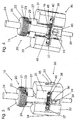
- Fig. 1 shows a perspective view of a motor vehicle door hinge 1.
- a door bracket 2 for connection to the vehicle door and a pillar bracket 4 for connection to the vehicle body.
- the door bracket 2 in this case has a door base plate 3, which has openings for receiving suitable fastening screws.
- a bracket 6 is arranged in a receptacle, via which the column bracket 4 is pivotally connected to a column bracket bracket 7, which in a column console base plate 5 of the column console 4 is attached.
- the pillar bracket 7 a pin receptacle 8, in which a pin 9 of the boom 6 is rotatably arranged.
- the arranged in the pin receiving 8 pin 9 thus forms a pivot axis 10 of the motor vehicle door hinge.
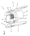
- a gear unit 14 Parallel to the pivot axis 10, a gear unit 14, a locking unit 16 and a control unit 30 is arranged along a common longitudinal axis.
- the control unit 30 and the locking unit 16 thereby form a detent 15 of the motor vehicle door hinge 1.
- the gear unit 14 has a drive shaft 12 on which a gear 11 is arranged rotationally fixed by a feather key 13.
- the gear 11 is engaged with the formed as a ring gear arm 6 into engagement, wherein the ring gear has an internal toothing.
- a pivoting of the door bracket 2 relative to the pillar bracket 4 thus causes via the gear formed as a ring gear 6 via the gear 11, a drive of the drive shaft 12 of the gear unit 14, which is arranged in a housing 17 (see. Fig. 2 ).
- a flange 25 and a receiving portion 26 adjoins the transmission output shaft 24, on which a disk set 20 consisting of inner disks 22 and outer disks 21 is arranged.
- the inner disks 22 have an inner profile with abutment surfaces 60 which ensure a rotationally secure arrangement of the inner disks 22 on the receiving portion 26 (cf. Fig. 3, 4 and 12 ).
- a pivoting movement of the door bracket 2 relative to the column console 4 thus causes via the gear unit 14, a rotation of the transmission output shaft 24, wherein the rotationally fixed to the transmission output shaft 24 connected to inner disks 22 relative to the rotationally fixed in the housing 18 of the lock 15 mounted outer plates 21 rotatable are.
- the force required for pivoting is determined as a function of the pressure acting on the disk pack 20, which rests at one end on the side facing away from the gear unit 14 of the flange 25.
- the pressure acting on the disk pack 20 is determined by a pressure element of the control unit 30 designed as a slide 27.
- the slider 27 is mounted axially displaceably on the control unit 30 along the common longitudinal axis.
- the slide 27 On its side facing the disk pack 20, the slide 27 has four openings 28 in which compression springs 29 are arranged, which abut with their ends facing away from the slide against the end of the disk pack 20 remote from the flange 25 (cf. Fig. 6 and Figure 13 ).
- a displacement of the slider 27 in the axial direction thus determines the state of the disk pack 20, namely whether this in the coupling state, in which a relative displaceability of the lamellae 21, 22 is possible only with increased effort, or in the disconnected state in which a relative pivotability easily is possible, since the lamellae 21, 22 can be rotated against each other.
- the position of the slider 27 is determined by the control unit 30.
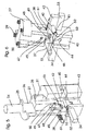
- the slider 27 is connected via two levers 48, of which only one is shown in the figures for simplicity, with controls 42, 55 which define the axial position of the slider 27 depending on their radial position relative to the longitudinal axis of the control unit 30 ( see. Fig. 7-11 ).
- the lever 48 is articulated to a projecting through a bore 50 of the slider 27 hinge pin 47, wherein the slider 27 has a recess 49 which allows a pivoting of the lever 48 relative to the slider 27.
- the lever 48 is articulated to the first control element 42 via a bolt 46 arranged in a bore 51 of the lever 48.
- a shift of the first Control element 42 is effected by a rotation of the control unit 30, wherein flyweights 31, 32 change their radial position relative to the longitudinal axis of the control unit 30, namely to be displaced outwards.
- the controls 42, 55 are biased towards each other by the flyweights 31, 32 arranged in bearing pin receivers 36, 54 bearing pins 37, 40, on which tension springs 38 are arranged.
- the tension springs 38 are arranged with their ends in a groove 41, which prevents slipping of the tension springs 38 of the bearing pin 37, 40. This bias ensures that at standstill of the control unit 30, the lever 48 is aligned substantially in the longitudinal axis direction of the control unit 30 and the slider 27 exerts the maximum pressure on the disk pack 20.
- a base body 43 of the control unit 30 has a pin 39 arranged in a pin receptacle 56, which is secured to the base body 43 by a screw 19 which can be screwed into a threaded bore 44.
- the control unit 30 is rotatably mounted in the housing 18 of the fastener 18.
- the main body also has two radially outwardly projecting guide body 33, 34, which are arranged in openings 35 of the flyweights 31, 32 and the movement of the flyweights 31, 32 in the case of rotation pretend.
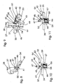
- a latch unit 57 is further arranged in the main body 43.
- the latching unit 57 has latching bodies 52 inserted in bores 53 of the main body 43, which are prestressed by compression springs 59 which, at their end facing away from the latching bodies 52, abut against adjusting screws 58 which can be screwed into the base body 43.
- the locking body 52 engage in the separation state associated with the positions of the controls 42, 55 in locking grooves 61, which at the control elements 42, 55 are arranged on the side facing the base body 43.
- the locking body 52 lock the controls 42, 55 after reaching the separation state and prevent a reduction in the rotational speed proportional restoring the controls 42, 55.
- the locking body 52 are designed such that they only at standstill of the rotation of the control unit 30, a transition of the controls 42, 55 in the coupling state associated position, as in Fig. 10 shown, allow.
- motor vehicle door hinge 1 The functioning of the in the Figures 1-13 shown motor vehicle door hinge 1 is due to the structure as follows.
- the slide 27 has the smallest distance to the disk pack 20.
- the lever 48 is arranged substantially in the longitudinal axis direction of the control unit 30.
- the flyweights 31, 32 are in their coupling position associated position.
- the door bracket 2 is thus locked relative to the pillar bracket 4 on the mutually acting inner and outer disks 21, 22.
- the transmission unit 14 converts the pivoting movement into a rotation of the control unit 30, wherein the centrifugal weights 31, 32 are displaced radially outwards with the control elements 42, 55.
- the slider 27 is pulled away from the disk pack 20, so that the pressure on the disk pack 20 decreases and this switches to the disconnected position, which allows easy pivoting.
Landscapes
- Engineering & Computer Science (AREA)
- Mechanical Engineering (AREA)
- Vehicle Step Arrangements And Article Storage (AREA)
- Hinges (AREA)
- Hinge Accessories (AREA)
Applications Claiming Priority (1)
| Application Number | Priority Date | Filing Date | Title |
|---|---|---|---|
| DE200710048791 DE102007048791B4 (de) | 2007-10-10 | 2007-10-10 | Kraftfahrzeugtürscharnier |
Publications (2)
| Publication Number | Publication Date |
|---|---|
| EP2048310A2 true EP2048310A2 (fr) | 2009-04-15 |
| EP2048310A3 EP2048310A3 (fr) | 2010-08-25 |
Family
ID=40193632
Family Applications (1)
| Application Number | Title | Priority Date | Filing Date |
|---|---|---|---|
| EP08016431A Withdrawn EP2048310A3 (fr) | 2007-10-10 | 2008-09-18 | Charnière de porte de véhicule automobile |
Country Status (2)
| Country | Link |
|---|---|
| EP (1) | EP2048310A3 (fr) |
| DE (1) | DE102007048791B4 (fr) |
Cited By (2)
| Publication number | Priority date | Publication date | Assignee | Title |
|---|---|---|---|---|
| WO2012013183A3 (fr) * | 2010-07-22 | 2012-06-14 | Kiekert Aktiengesellschaft | Unité de portière |
| CN107471977A (zh) * | 2017-07-03 | 2017-12-15 | 山东科技大学 | 一种带有防夹结构的公共交通车辆内翻式车门 |
Citations (1)
| Publication number | Priority date | Publication date | Assignee | Title |
|---|---|---|---|---|
| EP1144786B1 (fr) | 1999-01-15 | 2004-04-07 | ISE Industries GmbH | Joint d'articulation, notamment une charniere de porte, muni d'un dispositif permettant de fixer un premier element de mouvement |
Family Cites Families (3)
| Publication number | Priority date | Publication date | Assignee | Title |
|---|---|---|---|---|
| DE19854602A1 (de) * | 1998-11-26 | 2000-06-08 | Scharwaechter Ed Gmbh | An ein Türscharnier angeschlossener Türfeststeller für Kraftwagentüren |
| DE20200657U1 (de) * | 2002-01-16 | 2003-06-05 | Friedr. Fingscheidt GmbH, 42551 Velbert | Scharniertürhalter für Kraftfahrzeuge |
| DE10305977B4 (de) * | 2003-02-13 | 2005-06-16 | Edscha Ag | Scharnier |
-
2007
- 2007-10-10 DE DE200710048791 patent/DE102007048791B4/de not_active Expired - Fee Related
-
2008
- 2008-09-18 EP EP08016431A patent/EP2048310A3/fr not_active Withdrawn
Patent Citations (1)
| Publication number | Priority date | Publication date | Assignee | Title |
|---|---|---|---|---|
| EP1144786B1 (fr) | 1999-01-15 | 2004-04-07 | ISE Industries GmbH | Joint d'articulation, notamment une charniere de porte, muni d'un dispositif permettant de fixer un premier element de mouvement |
Cited By (3)
| Publication number | Priority date | Publication date | Assignee | Title |
|---|---|---|---|---|
| WO2012013183A3 (fr) * | 2010-07-22 | 2012-06-14 | Kiekert Aktiengesellschaft | Unité de portière |
| CN107471977A (zh) * | 2017-07-03 | 2017-12-15 | 山东科技大学 | 一种带有防夹结构的公共交通车辆内翻式车门 |
| CN107471977B (zh) * | 2017-07-03 | 2023-06-27 | 山东科技大学 | 一种带有防夹结构的公共交通车辆内翻式车门 |
Also Published As
| Publication number | Publication date |
|---|---|
| DE102007048791B4 (de) | 2009-11-05 |
| EP2048310A3 (fr) | 2010-08-25 |
| DE102007048791A1 (de) | 2009-04-16 |
Similar Documents
| Publication | Publication Date | Title |
|---|---|---|
| EP0751032B1 (fr) | Dispositif de réglage | |
| EP2122093B1 (fr) | Ferme-porte | |
| EP3708753B1 (fr) | Ferrure de couvercle destinée à la fixation pivotante d'un couvercle de meuble sur un corps de meuble | |
| EP2257682B1 (fr) | Bande pour la fixation pivotante d'un vantail, d'une porte, d'une fenetre ou similaires, sur un cadre fixe | |
| EP4244454A1 (fr) | Entraînement de meuble pour déplacer une partie de meuble montée mobile par rapport à un corps de meuble | |
| EP0962356B1 (fr) | Glissière de siège de véhicule à dispositif de verrouillage | |
| EP3211271A2 (fr) | Dispositif de réglage et systême de commande d'ouvrants comprenant le même | |
| EP1318926B1 (fr) | Dispositif de reglage de l'inclinaison d'un dossier | |
| WO2012076372A1 (fr) | Dispositif de fermeture et d'amortissement pour éléments de meuble mobiles | |
| EP3915829B1 (fr) | Ferrure de siège de véhicule et siège de véhicule | |
| DE102012212493A1 (de) | Drehsperre für Verstelleinrichtungen in Kraftfahrzeugen | |
| DE102016003992A1 (de) | Armlehne | |
| EP1659298B1 (fr) | Entraînement linéaire | |
| WO2025103541A1 (fr) | Dispositif d'ouverture pour porte de véhicule automobile | |
| DE102009004263A1 (de) | Parksperre für Automatikgetriebe und automatisierte Schaltgetriebe | |
| DE102007048791B4 (de) | Kraftfahrzeugtürscharnier | |
| EP1375803B1 (fr) | Charnière de porte notamment pour véhicules automobile | |
| WO2001017816A1 (fr) | Entrainement de dispositif de reglage de la hauteur pour un siege de vehicule | |
| DE3223707A1 (de) | Gelenkbeschlag fuer sitze mit verstellbarer rueckenlehne, insbesondere kraftfahrzeugsitze | |
| AT518634B1 (de) | Verstellturm für eine fernoptische Einrichtung | |
| DE10223460A1 (de) | Scharnier für eine Kraftfahrzeugtür | |
| DE102005038829B4 (de) | Vorrichtung zur Einstellung der Neigung eines Kraftfahrzeugscheinwerfers | |
| EP4047164B1 (fr) | Dispositif d'entraînement pour un appareil, agencement, ainsi qu'appareil électroménager | |
| DE102004036166B3 (de) | Kraftfahrzeugtürscharnier mit stufenloser Rastierung | |
| DE102006062127A1 (de) | Rastbeschlag für eine Verstellvorrichtung in einem Kraftfahrzeug |
Legal Events
| Date | Code | Title | Description |
|---|---|---|---|
| PUAI | Public reference made under article 153(3) epc to a published international application that has entered the european phase |
Free format text: ORIGINAL CODE: 0009012 |
|
| AK | Designated contracting states |
Kind code of ref document: A2 Designated state(s): AT BE BG CH CY CZ DE DK EE ES FI FR GB GR HR HU IE IS IT LI LT LU LV MC MT NL NO PL PT RO SE SI SK TR |
|
| AX | Request for extension of the european patent |
Extension state: AL BA MK RS |
|
| PUAL | Search report despatched |
Free format text: ORIGINAL CODE: 0009013 |
|
| AK | Designated contracting states |
Kind code of ref document: A3 Designated state(s): AT BE BG CH CY CZ DE DK EE ES FI FR GB GR HR HU IE IS IT LI LT LU LV MC MT NL NO PL PT RO SE SI SK TR |
|
| AX | Request for extension of the european patent |
Extension state: AL BA MK RS |
|
| AKY | No designation fees paid | ||
| STAA | Information on the status of an ep patent application or granted ep patent |
Free format text: STATUS: THE APPLICATION IS DEEMED TO BE WITHDRAWN |
|
| 18D | Application deemed to be withdrawn |
Effective date: 20110226 |