EP2048349A2 - Unité de moteur et véhicule doté de celle-ci - Google Patents
Unité de moteur et véhicule doté de celle-ci Download PDFInfo
- Publication number
- EP2048349A2 EP2048349A2 EP20080253291 EP08253291A EP2048349A2 EP 2048349 A2 EP2048349 A2 EP 2048349A2 EP 20080253291 EP20080253291 EP 20080253291 EP 08253291 A EP08253291 A EP 08253291A EP 2048349 A2 EP2048349 A2 EP 2048349A2
- Authority
- EP
- European Patent Office
- Prior art keywords
- throttle body
- throttle
- fuel
- supply pipe
- fuel supply
- Prior art date
- Legal status (The legal status is an assumption and is not a legal conclusion. Google has not performed a legal analysis and makes no representation as to the accuracy of the status listed.)
- Granted
Links
Images


Classifications
-
- F—MECHANICAL ENGINEERING; LIGHTING; HEATING; WEAPONS; BLASTING
- F02—COMBUSTION ENGINES; HOT-GAS OR COMBUSTION-PRODUCT ENGINE PLANTS
- F02D—CONTROLLING COMBUSTION ENGINES
- F02D9/00—Controlling engines by throttling air or fuel-and-air induction conduits or exhaust conduits
- F02D9/08—Throttle valves specially adapted therefor; Arrangements of such valves in conduits
- F02D9/10—Throttle valves specially adapted therefor; Arrangements of such valves in conduits having pivotally-mounted flaps
- F02D9/109—Throttle valves specially adapted therefor; Arrangements of such valves in conduits having pivotally-mounted flaps having two or more flaps
-
- F—MECHANICAL ENGINEERING; LIGHTING; HEATING; WEAPONS; BLASTING
- F02—COMBUSTION ENGINES; HOT-GAS OR COMBUSTION-PRODUCT ENGINE PLANTS
- F02D—CONTROLLING COMBUSTION ENGINES
- F02D11/00—Arrangements for, or adaptations to, non-automatic engine control initiation means, e.g. operator initiated
- F02D11/06—Arrangements for, or adaptations to, non-automatic engine control initiation means, e.g. operator initiated characterised by non-mechanical control linkages, e.g. fluid control linkages or by control linkages with power drive or assistance
- F02D11/10—Arrangements for, or adaptations to, non-automatic engine control initiation means, e.g. operator initiated characterised by non-mechanical control linkages, e.g. fluid control linkages or by control linkages with power drive or assistance of the electric type
-
- F—MECHANICAL ENGINEERING; LIGHTING; HEATING; WEAPONS; BLASTING
- F02—COMBUSTION ENGINES; HOT-GAS OR COMBUSTION-PRODUCT ENGINE PLANTS
- F02D—CONTROLLING COMBUSTION ENGINES
- F02D9/00—Controlling engines by throttling air or fuel-and-air induction conduits or exhaust conduits
- F02D9/08—Throttle valves specially adapted therefor; Arrangements of such valves in conduits
- F02D9/10—Throttle valves specially adapted therefor; Arrangements of such valves in conduits having pivotally-mounted flaps
- F02D9/1065—Mechanical control linkage between an actuator and the flap, e.g. including levers, gears, springs, clutches, limit stops of the like
-
- F—MECHANICAL ENGINEERING; LIGHTING; HEATING; WEAPONS; BLASTING
- F02—COMBUSTION ENGINES; HOT-GAS OR COMBUSTION-PRODUCT ENGINE PLANTS
- F02M—SUPPLYING COMBUSTION ENGINES IN GENERAL WITH COMBUSTIBLE MIXTURES OR CONSTITUENTS THEREOF
- F02M35/00—Combustion-air cleaners, air intakes, intake silencers, or induction systems specially adapted for, or arranged on, internal-combustion engines
- F02M35/10—Air intakes; Induction systems
- F02M35/10006—Air intakes; Induction systems characterised by the position of elements of the air intake system in direction of the air intake flow, i.e. between ambient air inlet and supply to the combustion chamber
- F02M35/10026—Plenum chambers
- F02M35/10032—Plenum chambers specially shaped or arranged connecting duct between carburettor or air inlet duct and the plenum chamber; specially positioned carburettors or throttle bodies with respect to the plenum chamber
-
- F—MECHANICAL ENGINEERING; LIGHTING; HEATING; WEAPONS; BLASTING
- F02—COMBUSTION ENGINES; HOT-GAS OR COMBUSTION-PRODUCT ENGINE PLANTS
- F02M—SUPPLYING COMBUSTION ENGINES IN GENERAL WITH COMBUSTIBLE MIXTURES OR CONSTITUENTS THEREOF
- F02M35/00—Combustion-air cleaners, air intakes, intake silencers, or induction systems specially adapted for, or arranged on, internal-combustion engines
- F02M35/10—Air intakes; Induction systems
- F02M35/104—Intake manifolds
- F02M35/116—Intake manifolds for engines with cylinders in V-arrangement or arranged oppositely relative to the main shaft
-
- F—MECHANICAL ENGINEERING; LIGHTING; HEATING; WEAPONS; BLASTING
- F02—COMBUSTION ENGINES; HOT-GAS OR COMBUSTION-PRODUCT ENGINE PLANTS
- F02M—SUPPLYING COMBUSTION ENGINES IN GENERAL WITH COMBUSTIBLE MIXTURES OR CONSTITUENTS THEREOF
- F02M35/00—Combustion-air cleaners, air intakes, intake silencers, or induction systems specially adapted for, or arranged on, internal-combustion engines
- F02M35/16—Combustion-air cleaners, air intakes, intake silencers, or induction systems specially adapted for, or arranged on, internal-combustion engines characterised by use in vehicles
- F02M35/162—Motorcycles; All-terrain vehicles, e.g. quads, snowmobiles; Small vehicles, e.g. forklifts
-
- F—MECHANICAL ENGINEERING; LIGHTING; HEATING; WEAPONS; BLASTING
- F02—COMBUSTION ENGINES; HOT-GAS OR COMBUSTION-PRODUCT ENGINE PLANTS
- F02B—INTERNAL-COMBUSTION PISTON ENGINES; COMBUSTION ENGINES IN GENERAL
- F02B61/00—Adaptations of engines for driving vehicles or for driving propellers; Combinations of engines with gearing
- F02B61/02—Adaptations of engines for driving vehicles or for driving propellers; Combinations of engines with gearing for driving cycles
-
- F—MECHANICAL ENGINEERING; LIGHTING; HEATING; WEAPONS; BLASTING
- F02—COMBUSTION ENGINES; HOT-GAS OR COMBUSTION-PRODUCT ENGINE PLANTS
- F02D—CONTROLLING COMBUSTION ENGINES
- F02D9/00—Controlling engines by throttling air or fuel-and-air induction conduits or exhaust conduits
- F02D9/08—Throttle valves specially adapted therefor; Arrangements of such valves in conduits
- F02D9/10—Throttle valves specially adapted therefor; Arrangements of such valves in conduits having pivotally-mounted flaps
- F02D9/1035—Details of the valve housing
- F02D9/105—Details of the valve housing having a throttle position sensor
Definitions
- the present invention relates to an engine unit and a vehicle provided with the same. More specifically, the invention relates to an engine unit comprising a V-type engine and a throttle body assembly and a vehicle provided with the same.
- Fig. 11 is a plan view showing a throttle body assembly 100 of a V-type engine described in JP-A-2002-256900 .
- Fig. 12 is a cross sectional view showing the throttle body assembly 100.
- a motor 102 is arranged in a region surrounded by throttle bodies 103, 104 as viewed in plan view.
- Throttle valves 101 are driven by the motor 102.
- a front fuel supply pipe 105 and a rear fuel supply pipe 106 are arranged above the motor 102 and between the throttle body 103 and the throttle body 104.
- a fuel is supplied to a front injector 107 from the front fuel supply pipe 105.
- the fuel is supplied to a rear injector 108 from the rear fuel supply pipe 106.
- the two fuel supply pipes 105, 106 are aligned on the throttle body assembly 100 in a longitudinal direction. Therefore, it is necessary to arrange the throttle body 103 and the throttle body 104 distant from each other. Also, the fuel supply pipes 105, 106 and the motor 102 are aligned in a vertical direction. Here, since the motor 102 vibrates due to vibrations of an engine, etc., it is necessary to provide some clearance between the fuel supply pipes 105, 106 and the motor 102. Therefore, the fuel supply pipes 105, 106 and the motor 102 must be arranged away from each other. Accordingly, the throttle body assembly 100 becomes large in height dimension. That is, with the construction shown in Figs. 11 and 12 , it is difficult to make the throttle body assembly sufficiently small in size. Accordingly, there is caused a problem that it is difficult to make an engine unit, which includes a throttle body assembly, small in size.
- the invention seeks provide an engine unit being small both in height dimension and longitudinal length.
- An embodiment of an engine unit according to the invention comprises a V-type engine and a throttle body assembly.
- the V-type engine is formed with a front cylinder, a rear cylinder, a front intake port, and a rear intake port.
- the front intake port is connected to the front cylinder.
- the rear intake port is connected to the rear cylinder.
- the throttle body assembly is mounted to the V-type engine.
- the throttle body assembly includes a front throttle body, a rear throttle body, a fuel supply pipe, and a motor.
- the front throttle body is formed with a front air cylinder.
- the front air cylinder is connected to the front intake port.
- the front throttle body includes a front throttle valve for opening and closing of the front air cylinder.
- the rear throttle body is formed with a rear air cylinder.
- the rear air cylinder is connected to the rear intake port.
- the rear throttle body includes a rear throttle valve for opening and closing of the rear air cylinder.
- the fuel supply pipe is arranged between a central axis of the front air cylinder and a central axis of the rear air cylinder in a longitudinal direction.
- the fuel supply pipe extends widthwise in a lower position than a higher one of an upper end of the front throttle body and an upper end of the rear throttle body.
- the fuel supply pipe supplies a fuel to the front air cylinder and the rear air cylinder.
- the motor includes a rotating shaft extending in a width direction.
- the motor is arranged between the central axis of the front air cylinder and the central axis of the rear air cylinder in a longitudinal direction.
- the motor drives the front throttle valve and the rear throttle valve.
- An axis of the rotating shaft of the motor is positioned forwardly or rearwardly of a central axis of the fuel supply pipe.
- An embodiment of the invention can provide an engine unit that is small both in a height dimension and longitudinal length.
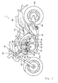
- a vehicle according to an embodiment of the invention is not limited to the motorcycle 1 shown in Fig. 1 .
- a vehicle according to an embodiment of the invention may be a four-wheel car or a straddle-type vehicle.
- "straddle-type vehicle” means a vehicle of a type, in which a rider straddles a seat (straddle).
- Straddle-type vehicles include ATV (All Terrain Vehicle), etc. in addition to a motorcycle.
- a motorcycle is not limited to a so-called American type shown in Fig. 1 .
- motorcycles can include any type of motorcycle and includes with this meaning a moped, scooter, off-road vehicle, etc.
- a motorcycle includes a vehicle comprising a plurality of wheels, of which at least one of a front wheel and a rear wheel rotates integrally, and inclined to change a traveling direction.
- longitudinal and left and right directions mean ones seen in a state of being seated on a seat 14.
- Fig. 1 is a schematic side view showing a motorcycle 1.
- the motorcycle 1 comprises a body frame 10, a body cover 13, and a seat 14.
- the body cover 13 covers a part of the body frame 10.
- the seat 14 is arranged on the body frame 10.
- the body frame 10 comprises a main frame 11 and a rear frame 12.
- the main frame 11 comprises a pair of left and right frame portions 11a, 11b extending rearward from a head pipe 15.
- the head pipe 15 is mounted to the main frame 11 to be able to turn.
- a handle 16 is fixed to an upper end of the head pipe 15 by a handle holder (not shown).
- a throttle grip 17 as a throttle operating element is provided on the handle 16.
- the throttle grip 17 is connected to an accelerator position sensor (APS) 51 by a throttle wire 18. Therefore, when the throttle grip 17 is operated by a rider, the throttle wire 18 is moved and a manipulated variable of the throttle grip 17 is detected as an accelerator position by the accelerator position sensor 51.
- APS accelerator position sensor
- a pair of left and right, front forks 20 are fixed to the head pipe 15.
- the front forks 20 are extended forward and obliquely downward.
- a front wheel 21 is mounted rotatably to lower ends of the front forks 20.
- a pivot shaft 22 is mounted to a rear end of the body frame 10.
- a rear arm 23 is mounted to the pivot shaft 22 to be able to swing.
- a rear wheel 24 is mounted rotatably to a rear end of the rear arm 23.
- the rear wheel 24 is connected to an output shaft of an engine unit 30 described later by a power transmission mechanism (not shown) of a drive shaft or the like. Thereby, power of the engine unit 30 is transmitted to the rear wheel 24 and the rear wheel 24 is rotated.
- the engine unit 30 is suspended from the main frame 11.
- the engine unit 30 comprises a V-type engine 31, a throttle body assembly 50, a clutch, and a transmission mechanism, which are not shown.
- the throttle body assembly 50 is arranged on the engine 31. As shown in Fig. 4 , the throttle body assembly 50 is arranged between the pair of left and right frame portions 11a, 11b as viewed in plan view.
- An insulator 48 is arranged between the engine unit 30 and the throttle body assembly 50.
- the insulator 48, the engine 31, and the throttle body assembly 50 are fixed to one another by X members 82a, 82b arranged on both sides in a vehicle width direction.
- the insulator 48 is formed with communication paths 48a, 48b.
- Intake ports 42a, 42b of the engine 31 and respective air cylinders 55, 56 of the throttle body assembly 50 are connected together by the communication paths 48a, 48b.
- an air cleaner 49 as an intake part is arranged above the throttle body assembly 50.
- An outside air is supplied to the throttle body assembly 50 through the air cleaner 49.
- an air chamber may be arranged as an intake part in place of the air cleaner 49.
- a fuel tank 19 is arranged rearwardly of the engine 31.
- the fuel tank 19 is connected to a fuel nipple 82 of the throttle body assembly 50, shown in Fig. 4 , by a fuel supply hose (not shown). Therefore, a fuel stored in the fuel tank 19 is supplied to the throttle body assembly 50 via the fuel supply hose.
- An air and a fuel supplied to the throttle body assembly 50 are mixed in the throttle body assembly 50 to create an air-fuel mixture.
- the air-fuel mixture is supplied to the engine 31 from the throttle body assembly 50.
- a battery 47 that supplies electricity to the engine unit 30 and the throttle body assembly 50 is mounted just rearwardly of the throttle body assembly 50 in a space surrounded by the main frame 11 as viewed in plan view.
- the engine 31 is a water-cooled four-stroke V-type four-cylinder engine. In an embodiment of the invention, however, the engine 31 can be any V-type engine.
- the engine 31 may be an air-cooled engine.
- the engine 31 may be a two-stroke engine.
- the engine 31 may be a V-type engine having three or less cylinders or five or more cylinders.
- V-type engine referred to here means an engine including front cylinders and rear cylinders, which are arranged to define a V bank.
- the matter “front cylinders and rear cylinders are arranged to define a V bank” means that front cylinders and rear cylinders are arranged so that central axes of the front cylinders and central axes of the rear cylinders intersect each other obliquely about an axis of a crank shaft.
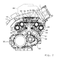
- the engine 31 comprises a crank case 32.
- a crank shaft (not shown) is received in the crank case 32.
- a front cylinder body 33 and a rear cylinder body 35 are mounted to the crank case 32.
- the front cylinder body 33 and the rear cylinder body 35 are arranged in a V-shaped manner about the crank shaft as viewed in side view.
- a front cylinder head 36 is mounted above the front cylinder body 33.
- a front head cover 38 is mounted further above the front cylinder head 36.
- a rear cylinder head 37 is mounted above the rear cylinder body 35.
- a rear head cover 39 is mounted above the rear cylinder head 37.
- substantially columnar-shaped front cylinders 34 are formed in the front cylinder body 33.
- substantially columnar-shaped rear cylinders 29 are formed in the rear cylinder body 35.
- the front cylinders 34 and the rear cylinders 29 are arranged to define a V bank. More specifically, while the front cylinders 34 are arranged upward and obliquely forward, the rear cylinders 29 are arranged upward and obliquely rearward.
- An angle ⁇ 0 formed between central axes of the front cylinders 34 and central axes of the rear cylinders 29 and shown in Fig.
- ⁇ 1 is set to a magnitude, which eliminates a positional interference between the front cylinders 34 and the rear cylinders 29, or more in view of engine sound generated from the engine 31 and characteristics of the engine 31 being obtained.
- ⁇ 0 is usually set to at least 10° and at most 170°, preferably, at least 30° and at most 150°, and more preferably, at least 45° and at most 100°.
- connecting rods 40a, 40b, respectively, connected to a crank shaft are received in the front cylinders 34 and the rear cylinders 29, respectively.
- Pistons 41a, 41b are mounted to tip ends of the connecting rods 40a, 40b.
- Combustion chambers 47a, 47b are compartmented and formed by the pistons 41a, 41b, the cylinders 34, 29, and the cylinder heads 36, 37.
- the intake ports 42a, 42b and exhaust ports 43a, 43b are formed in the front cylinder head 36 and the rear cylinder head 37, respectively.
- Intake valves 44a, 44b for opening and closing of the intake ports 42a, 42b are arranged on the intake ports 42a, 42b.
- the intake valves 44a, 44b are driven by intake cams 46a, 46b arranged on upper surfaces of the intake valves 44a, 44b.
- exhaust valves 45a, 45b for opening and closing of the exhaust ports 43 are arranged on the exhaust ports 43a, 43b.
- the exhaust valves 45a, 45b are driven by exhaust cams (not shown).
- the throttle body assembly 50 comprises a first, front throttle body 53a and a second, front throttle body 53b.
- first, front throttle body 53a and second, front throttle body 53b is generally referred to as “front throttle bodies 53" in the following some descriptions.
- the first, front throttle body 53a and the second, front throttle body 53b are arranged in a vehicle width direction.
- the first, front throttle body 53a is formed with a substantially columnar-shaped first, front air cylinder 55a.
- the second, front throttle body 53b is formed with a substantially columnar-shaped second front air cylinder 55b.
- the front air cylinder 55a and the rear air cylinder 55b, respectively, are extended vertically.
- the first, front air cylinder 55a and the second front air cylinder 55b are generally referred to as "front air cylinders 55" in some cases.
- the front throttle bodies 53a, 53b, respectively, include front throttle valves 57a, 57b.
- front throttle valves 57a, 57b is generally referred to as “front throttle valves 57” in the following some descriptions.
- the front throttle valve 57a and the front throttle valve 57b are connected to each other by a valve stem 65.
- the valve stem 65 is rotated by a motor 60 described later whereby the front throttle valve 57a and the front throttle valve 57b are moved simultaneously, so that the front air cylinders 55a, 55b are opened and closed.
- a first rear throttle body 54a and a second rear throttle body 54b are arranged rearwardly of the front throttle bodies 53a, 53b.
- first rear throttle body 54a and second rear throttle body 54b is generally referred to as “rear throttle bodies 54" in the following some descriptions.
- the first rear throttle body 54a and the second rear throttle body 54b are aligned in a vehicle width direction.
- the first rear throttle body 54a is arranged substantially rearwardly of the first, front throttle body 53a.
- the second rear throttle body 54b is arranged substantially rearwardly of the second, front throttle body 53b.
- the front throttle bodies 53a, 53b and the rear throttle bodies 54a, 54b are arranged a little offset from each other in the vehicle width direction.
- an upper end of the first, front throttle body 53a, an upper end of the second, front throttle body 53b, an upper end of the first rear throttle body 54a, and an upper end of the second rear throttle body 54b are positioned in the same level.
- the first rear throttle body 54a is formed with a first, rear air cylinder 56a substantially in the form of a column.
- the second rear throttle body 54b is formed with a second rear air cylinder 56b substantially in the form of a column.
- first rear air cylinder 56a and second rear air cylinder 56b is generally referred to as “rear air cylinders 56" in the following some descriptions.
- the rear throttle bodies 54a, 54b, respectively, include rear throttle valves 58a, 58b.
- "Rear throttle valves 58a, 58b” is generally referred to as “rear throttle valves 58" hereinbelow.
- the rear throttle valve 58a and the rear throttle valve 58b are connected to each other by a valve stem 66. Therefore, the valve stem 66 is rotated by the motor 60 described later whereby the rear throttle valves 58a, 58b are moved simultaneously, so that the rear air cylinders 56a, 56b are opened and closed.
- an upper end of the front air cylinder 55 and an upper end of the rear air cylinder 56 are connected to the air cleaner 49.
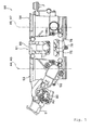
- a lower end of the front air cylinders 55 and a lower end of the rear air cylinders 56 are connected to intake ports 42a, 42b as shown in Fig. 3 .
- an air sucked from the air cleaner 49 is supplied to the engine 31 through the throttle body assembly 50.
- front injectors 75a, 75b are mounted to the front throttle bodies 53a, 53b, respectively.
- rear injectors 76a, 76b are mounted to the rear throttle bodies 54a, 54b, respectively.
- Front injectors 75a, 75b is generally referred to as “front injectors 75” hereinbelow in some cases.
- Front injectors 76a, 76b is generally referred to as “rear injectors 76" in some cases.
- the front injectors 75 and the rear injectors 76 are connected at respective upper ends to a fuel supply pipe 81.
- the fuel supply pipe 81 is extended between the front air cylinders 55 and the rear air cylinders 56 in the vehicle width direction. More specifically, the fuel supply pipe 81 is arranged so that its central axis A2 is positioned centrally between central axes A4, A5 of the front air cylinders 55 and central axes A6, A7 of the rear air cylinders 56 in a longitudinal direction.
- the fuel supply pipe 81 is arranged in a position lower than upper ends of the front throttle bodies 53 and upper ends of the rear throttle bodies 54 but higher than lower ends of the front throttle bodies 53 and lower ends of the rear throttle bodies 54 in a vertical direction.
- the fuel supply pipe 81 is preferably arranged in a position lower than higher ones of the upper ends of the front throttle bodies 53 and the upper ends of the rear throttle bodies 54.
- the fuel nipple 82 is connected to the fuel supply pipe 81.
- the fuel nipple 82 is extended rearwardly of the fuel supply pipe 81 between the first, rear air cylinder 56a and the second rear air cylinder 56b.
- the fuel nipple 82 is connected to the fuel tank 19 by a fuel supply pipe (not shown). Thereby, a fuel stored in the fuel tank 19 is supplied to the front injectors 75 and the rear injectors 76 through the fuel supply pipe, the fuel nipple 82 and the fuel supply pipe 81.
- a pulsation damper 83 is mounted to the fuel supply pipe 81.
- the pulsation damper 83 is positioned rearwardly of and a little obliquely downwardly of the fuel supply pipe 81.
- the pulsation damper 83 suppresses pulsation of a fuel supplied to the front injectors 75 and the rear injectors 76.
- nozzles 73 mounted to tip ends of the front injectors 75 and shown in Fig. 3 are regulated so that a fuel jetted from the front injectors 75 is jetted centering around directions along central axes of the front air cylinders 55.
- nozzles 74 mounted to tip ends of the rear injectors 76 are regulated so that a fuel is jetted centering around directions along central axes of the rear air cylinders 56.
- the front injectors 75a, 75b comprise injector bodies 68a, 68b and first front connectors 77a, 77b.
- the rear injectors 76a, 76b comprise injector bodies 69a, 69b and first rear connectors 78a, 78b.
- injector bodies 68a, 68b is generally referred to as “injector bodies 68" hereinbelow in some cases.
- First front connectors 77a, 77b” is generally referred to as “front connectors 77” in some cases.
- “Injector bodies 69a, 69b” is generally referred to as “injector bodies 69" in some cases.
- First rear connectors 78a, 78b” is generally referred to as “rear connectors 78" in some cases.
- the connectors 77, 78 are connected to ECU (Electronic Control Unit) 80. shown in Fig. 10 . Control signals are output to the front injectors 75 and the rear injectors 76 from the ECU 80 through the connectors 77, 78 whereby fuel injection from the front injectors 75 and the rear injectors 76 is controlled.
- Fig. 6 is a right side view showing the throttle body assembly 50 but depiction of a right fixing plate 88a shown in Fig. 4 is omitted for the convenience of showing a configuration of the connectors 77, 78.
- the injector bodies 68, 69 are extended in a longitudinal direction as viewed in plan view.
- the connectors 77, 78 are extended obliquely in the longitudinal direction as viewed in plan view.
- the first front connector 77a and the second front connector 77b are extended obliquely rearward in mutually opposite senses in the vehicle width direction. More specifically, the first front connector 77a and the second front connector 77b, respectively, are extended obliquely rearward and outward in the vehicle width direction.
- the first rear connector 78a and the second rear connector 78b are extended obliquely rearward in mutually opposite senses in the vehicle width direction. More specifically, the first rear connector 78a and the second rear connector 78b, respectively, are extended obliquely rearward and outward in the vehicle width direction.
- An angle formed, as viewed in plan view, between a central axis of the injector body 68a positioned outward in the vehicle width direction and a direction, in which the first front connector 77a is extended, and an angle formed, as viewed in plan view, between a central axis of the injector body 69b and a direction, in which the second rear connector 78b is extended, are equally set to ⁇ 1 .
- an angle formed, as viewed in plan view, between a central axis of the injector body 68b positioned inward in the vehicle width direction and a direction, in which the second front connector 77b is extended, and an angle formed, as viewed in plan view, between a central axis of the injector body 69a and a direction, in which the first rear connector 78a is extended, are equally set to ⁇ 2 .
- the same ⁇ 1 and ⁇ 2 are set in that range, in which the front connectors 77 and the rear connectors 78 do not positionally interfere with each other.
- ⁇ 1 and ⁇ 2 range preferably in 5° to 180°.
- the throttle body assembly 50 includes the motor 60. As shown in Fig. 9 , the motor 60 includes a rotating shaft 60a as a first rotating shaft. An axis A1 of the rotating shaft 60a extends in the vehicle width direction.
- a motor pinion gear 61 is mounted to the rotating shaft 60a.
- the motor pinion gear 61 meshes with a transmission gear mechanism 62.
- the transmission gear mechanism 62 comprises three idle gears 63a, 63b, 63c and two counter gears 64a, 64b.
- the counter gear 64a is fixed to the valve stem 65.
- the counter gear 64b is fixed to the valve stem 66.
- the motor pinion gear 61 meshes with the counter gear 64a through the single idle gear 63a.
- the motor pinion gear 61 and the counter gear 64b are relatively distant from each other, the motor pinion gear 61 meshes with the counter gear 64b through the two idle gears 63b, 63c.
- the motor 60 and the transmission gear mechanism 62 are generally referred to as a throttle valve driving mechanism 59.
- the motor 60 as an actuator is arranged in a region surrounded by the central axis A4 of the first, front air cylinder 55a, the central axis A5 of the second front air cylinder 55b, the central axis A6 of the first, rear air cylinder 56a, and the central axis A7 of the second rear air cylinder 56b as viewed in plan view.
- the motor 60 is arranged in a position lower than the upper ends of the front throttle bodies 53 and the rear throttle bodies 54 but higher than the lower ends thereof in the vertical direction. That is, the motor 60 is positioned in a space surrounded by four throttle bodies, that is, the front throttle bodies 53a, 53b and the rear throttle bodies 54a, 54b.
- the motor 60 is made offset from the fuel supply pipe 81 in the longitudinal direction.
- the axis A1 of the rotating shaft 60a as a first rotating shaft of the motor 60 and the central axis A2 of the fuel supply pipe 81 are positioned in different locations in the longitudinal direction. More specifically, the axis A1 is positioned forwardly of the central axis A2 of the fuel supply pipe 81. That is, as shown in Fig. 9 , the motor 60 is arranged so that the axis A1 is positioned between the central axis A2 of the fuel supply pipe 81 and the central axes A4, A5 of the front air cylinders 55 in the longitudinal direction.
- the motor 60 and the transmission gear mechanism 62 are received in a casing 70.
- the valve stems 65, 66 connected to the transmission gear mechanism 62 are inserted into the casing 70.
- the casing 70 comprises a first casing portion 71 and a second casing portion 72, which butt against each other in the vehicle width direction.
- the first casing portion 71 and the second casing portion 72 are fixed to each other by bolts, rivets, or the like.
- the first casing portion 71 is positioned on a side toward the transmission gear mechanism 62.
- the first casing portion 71 is formed from a metal.
- the first casing portion 71 can be formed from, for example, an alloy of iron, aluminum, stainless steel, etc.
- the first casing portion 71 is formed by aluminum die casting.
- the first casing portion 71 is fixed to the first, front throttle body 53a and the first rear throttle body 54a. Specifically, that portion of the casing 70, in which the transmission gear mechanism 62 is received and into which the valve stems 65, 66 are inserted, is fixed directly to the first, front throttle body 53a and the first rear throttle body 54a.
- the second casing portion 72 is positioned on a side toward the motor 60.
- the second casing portion 72 is formed from a resin.
- the second casing portion 72 can be formed from, for example, polybutylene terephthalate (PBT), etc.
- that resin, which forms the second casing portion 72 may contain, for example, glass fiber, etc.
- the second casing portion 72 may be formed from a metal.
- the second casing portion 72 is fixed to the second rear throttle body 54b.
- the second casing portion 72 is fixed to the second rear throttle body 54b through a metallic stay 67. More specifically, the stay 67 is bolted to a top of that portion of the second casing portion 72, in which the motor 60 is received, and also bolted to the second rear throttle body 54b whereby the second casing portion 72 is fixed to the second rear throttle body 54b.
- the connecting member 85 includes two inner connection pipes 86a, 86b, two outer connection pipes 87a, 87b, a right fixing plate 88a, and a left fixing plate 88b.
- the inner connection pipes 86a, 86b and the outer connection pipes 87a, 87b are extended in the vehicle width direction. As shown in Fig. 6 , the inner connection pipes 86a, 86b and the outer connection pipes 87a, 87b are arranged in positions different in level from each other. Specifically, the inner connection pipes 86a, 86b are arranged in substantially the same positions as upper ends of the throttle bodies 53, 54 in a height direction. On the other hand, the outer connection pipes 87a, 87b are arranged in substantially the same positions as central portions of the throttle bodies 53, 54 in the height direction.
- the inner connection pipes 86a, 86b are arranged between the central axes A4, A5 of the front air cylinders 55 and the central axes A6, A7 of the rear air cylinders 56.
- the inner connection pipe 86a is fixed to the first, front throttle body 53a and the second, front throttle body 53b rearwardly of the central axes A4, A5 of the front air cylinders 55.
- the inner connection pipe 86b is fixed to the first rear throttle body 54a and the second rear throttle body 54b forwardly of the central axes A6, A7 of the rear air cylinders 56.
- the inner connection pipe 86a and the inner connection pipe 86b are fixed to each other in two locations by two fixing members 89 in a width direction.
- the first and second connection pipes 86a, 86b and the two fixing members 89 are generally referred to as "inner connecting member 91" in the following descriptions.
- the outer connection pipe 87a is fixed to the first, front throttle body 53a and the second, front throttle body 53b forwardly of the central axes A4, A5 of the front air cylinders 55.
- the outer connection pipe 87b is fixed to the first rear throttle body 54a and the second rear throttle body 54b rearwardly of the central axes A6, A7 of the rear air cylinders 56.
- first, front throttle body 53a and the second, front throttle body 53b are firmly fixed and interposed by the inner connection pipe 86a and the outer connection pipe 87a.
- first rear throttle body 54a and the second rear throttle body 54b are firmly fixed and interposed by the inner connection pipe 86b and the outer connection pipe 87b.
- the front throttle bodies 53a, 53b and the rear throttle bodies 54a, 54b are fixed to each other by the right fixing plate 88a as a right fixing member and the left fixing plate 88b as a left fixing member.
- the left fixing plate 88b is fixed in four locations, that is, upper and lower portions of the second, front throttle body 53b and upper and lower portions of the second rear throttle body 54b.
- the right fixing plate 88a is fixed in four locations, that is, upper and lower portions of the first, front throttle body 53a and upper and lower portions of the first rear throttle body 54a.
- the front throttle bodies 53a, 53b and the rear throttle bodies 54a, 54b are fixed by the right fixing plate 88a, the left fixing plate 88b, and the inner connecting member 91.
- the inner connecting member 91 as a connecting member that fixes the front throttle bodies 53a, 53b and the rear throttle bodies 54a, 54b to each other is arranged in a region surrounded by the central axes A4, A5 and the central axes A6, A7. In the region surrounded by the central axes A4, A5 and the central axes A6, A7, any connecting member that fixes the front throttle bodies 53a, 53b and the rear throttle bodies 54a, 54b to each other is not arranged below the fuel supply pipe 81.
- the throttle body assembly 50 is provided with the accelerator position sensor 51 and a throttle position sensor 52.
- the throttle position sensor 52 is arranged on the left of the second, front throttle body 53b.
- the throttle position sensor 52 is connected to the valve stem 65.
- the throttle position sensor 52 detects rotation of the valve stem 65 to thereby detect a throttle position.
- the accelerator position sensor 51 is connected to a right end of an APS shaft 90 as a second rotating shaft.
- the APS shaft 90 is arranged so that an axis A3 of the APS shaft 90 is positioned in a lower position than the upper ends of the front throttle bodies 53 and the rear throttle bodies 54.
- the APS shaft 90 is preferably arranged so that the axis A3 is positioned in a lower position than higher ones of the upper ends of the front throttle bodies 53 and the upper ends of the rear throttle bodies 54.
- the motor 60 is arranged in a region surrounded by the central axes A4, A5 of the front air cylinders 55 and the central axes A6, A7 of the rear air cylinders 56 while the APS shaft 90 is arranged outside the region.
- the APS shaft 90 is arranged so that a central axis A3 of the APS shaft 90 is positioned forwardly of the central axes A4, A5 of the front air cylinders 55 in a longitudinal direction.
- the APS shaft 90 is arranged between the front head cover 38 and the air cleaner 49 as viewed in side view. In this manner, the APS shaft 90 and the motor 60 are made offset from each other in the longitudinal direction.
- a pulley 92 is mounted to the APS shaft 90.
- a throttle wire 18 shown in Fig. 1 is wound round the pulley 92. Therefore, the throttle grip 17 is manually operated whereby the APS shaft 90 rotates when the throttle wire 18 moves.
- the accelerator position sensor 51 detects rotation of the APS shaft 90 to thereby detect an accelerator position.
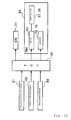
- the motorcycle 1 comprises an ECU (Electronic Control Unit) 80 as a control unit.
- ECU 80 Electronic Control Unit 80
- various sensors such as the accelerator position sensor 51, the throttle position sensor 52, a speed sensor 94, etc. described above.
- the accelerator position sensor 51 outputs an accelerator position to the ECU 80.
- the throttle position sensor 52 outputs a throttle position to the ECU 80.
- the speed sensor 94 outputs a car speed to the ECU 80.
- the engine 31 is connected to the ECU 80.
- the ECU 80 controls the engine 31 on the basis of accelerator position, throttle position, car speed, etc. as input.
- the throttle body assembly 50 is also connected to the ECU 80.
- the motor 60 and the injectors 75, 76 are connected to the ECU 80.
- the ECU 80 drives the motor 60 on the basis of accelerator position, throttle position, car speed, etc. as input.
- the motor 60 is driven whereby the valve stem 65 and the valve stem 66 are rotated.
- the throttle valves 57, 58 are moved to open and close the front air cylinders 55 and the rear air cylinders 56. Consequently, an air sucked from the air cleaner 49 is led into the air cylinders 55, 56.
- the ECU 80 controls the quantity of a fuel supplied from the injectors 75, 76 on the basis of accelerator position, throttle position, car speed, etc. as input.
- a fuel jetted from the injectors 75, 76 and an air supplied from the air cleaner 49 are mixed to create an air-fuel mixture.
- the air-fuel mixture as mixed is supplied to the intake ports 42a, 42b shown in Fig. 3 .
- the motor 60 and the fuel supply pipe 81 are made offset from each other in the longitudinal direction.
- the axis A1 of the rotating shaft 60a which is largest in height dimension in the motor 60
- the central axis A2 of the fuel supply pipe 81 are positionally shifted in the longitudinal direction. Therefore, it is possible to arrange the motor 60 and the fuel supply pipe 81 close to each other in a height direction. Accordingly, it is possible to make the throttle body assembly 50 small in height dimension. That is, by arranging the motor 60 between the front throttle bodies 53 and the rear throttle bodies 54 in the longitudinal direction and making the motor 60 and the fuel supply pipe 81 offset from each other in the longitudinal direction, it is possible to make the throttle body assembly 50 small both in longitudinal dimension and in height dimension. Accordingly, it is possible to make the engine unit 30 small both in longitudinal dimension and in height dimension.
- straddle-type vehicles in particular, motorcycles among various vehicles are strictly restricted in car width and car height. Therefore, a space, in which the throttle body assembly 50 and the engine unit 30 are arranged, is strictly restricted. In particular, a space, in which the throttle body assembly 50 and the engine unit 30 are arranged, is further strictly restricted on a motorcycle having the throttle body assembly 50 arranged between the pair of left and right frame portions 11a, 11b as viewed in plan view. Accordingly, the invention capable of making the engine unit 30 small in size is especially useful in straddle-type vehicles, in particular, motorcycles.
- the fuel supply pipe 81 is common to the front injectors 75 and the rear injectors 76. Therefore, as shown in Figs. 11 and 12 , the front injectors 75 and the rear injectors 76 can be arranged close to each other as compared with the case where exclusive fuel supply pipes are provided for the front injectors 75 and the rear injectors 76. Accordingly, it is possible to decrease the throttle body assembly 50 in length in the longitudinal direction. Consequently, it becomes possible to make a V bank angle ⁇ 0 of the engine 31 small.
- the motor 60 and the fuel nipple 82 are made offset from the fuel supply pipe 81 on separate sides from each other. Therefore, it is possible to prevent positional interference between the motor 60 and the fuel nipple 82. Accordingly, it becomes possible to make the throttle body assembly 50 and hence the engine unit 30 further small in size.
- the fuel nipple 82 is extended rearward. Therefore, as shown in Fig. 1 , the fuel tank 19 arranged rearwardly of the throttle body assembly 50 and the fuel nipple 82 are readily connected to each other. It is possible to shorten a fuel supply hose for connection of the fuel tank 19 and the fuel nipple 82.
- the motor 60 and the pulsation damper 83 are made offset from the fuel supply pipe 81 on separate sides from each other. Therefore, it is possible to prevent positional interference between the motor 60 and the pulsation damper 83. Accordingly, it becomes possible to make the throttle body assembly 50 and hence the engine unit 30 further small in size.
Landscapes
- Engineering & Computer Science (AREA)
- Chemical & Material Sciences (AREA)
- Combustion & Propulsion (AREA)
- Mechanical Engineering (AREA)
- General Engineering & Computer Science (AREA)
- Control Of Throttle Valves Provided In The Intake System Or In The Exhaust System (AREA)
- Automatic Cycles, And Cycles In General (AREA)
- Fuel-Injection Apparatus (AREA)
Applications Claiming Priority (1)
| Application Number | Priority Date | Filing Date | Title |
|---|---|---|---|
| JP2007264683A JP2009092020A (ja) | 2007-10-10 | 2007-10-10 | エンジンユニット及びそれを備えた車両 |
Publications (3)
| Publication Number | Publication Date |
|---|---|
| EP2048349A2 true EP2048349A2 (fr) | 2009-04-15 |
| EP2048349A3 EP2048349A3 (fr) | 2014-01-22 |
| EP2048349B1 EP2048349B1 (fr) | 2015-12-09 |
Family
ID=40119366
Family Applications (1)
| Application Number | Title | Priority Date | Filing Date |
|---|---|---|---|
| EP08253291.2A Active EP2048349B1 (fr) | 2007-10-10 | 2008-10-09 | Unité de moteur et véhicule doté de celle-ci |
Country Status (5)
| Country | Link |
|---|---|
| US (1) | US8042521B2 (fr) |
| EP (1) | EP2048349B1 (fr) |
| JP (1) | JP2009092020A (fr) |
| CN (1) | CN101408134B (fr) |
| ES (1) | ES2561487T3 (fr) |
Families Citing this family (4)
| Publication number | Priority date | Publication date | Assignee | Title |
|---|---|---|---|---|
| US8176881B2 (en) | 2005-02-07 | 2012-05-15 | Emerson Electric Co. | Systems and methods for controlling a water heater |
| JP2009092019A (ja) * | 2007-10-10 | 2009-04-30 | Yamaha Motor Co Ltd | エンジンユニット及びそれを有する車両 |
| KR101145630B1 (ko) * | 2009-12-03 | 2012-05-16 | 기아자동차주식회사 | 엔진의 흡기 시스템 |
| JP5577887B2 (ja) * | 2010-06-29 | 2014-08-27 | スズキ株式会社 | V型エンジンの燃料供給装置 |
Citations (1)
| Publication number | Priority date | Publication date | Assignee | Title |
|---|---|---|---|---|
| JP2002256900A (ja) | 2001-03-05 | 2002-09-11 | Yamaha Motor Co Ltd | V型エンジンのスロットル制御装置 |
Family Cites Families (7)
| Publication number | Priority date | Publication date | Assignee | Title |
|---|---|---|---|---|
| US2869527A (en) * | 1956-07-12 | 1959-01-20 | Gen Motors Corp | Charge forming means for an internal combustion engine |
| JP2002364467A (ja) * | 2001-06-08 | 2002-12-18 | Yamaha Motor Co Ltd | エンジンの吸気装置 |
| JP4341811B2 (ja) * | 2003-04-04 | 2009-10-14 | 本田技研工業株式会社 | スロットルバルブ開度制御装置 |
| JP4430552B2 (ja) * | 2005-01-18 | 2010-03-10 | 株式会社ケーヒン | V型機関用の吸気装置 |
| JP4600110B2 (ja) * | 2005-03-23 | 2010-12-15 | スズキ株式会社 | 自動二輪車におけるv型エンジンの吸気装置 |
| EP1884658B1 (fr) * | 2006-08-03 | 2011-06-08 | Keihin Corporation | Structure de conduit de distribution de carburant dans un corps à papillons multiples |
| JP4634355B2 (ja) * | 2006-09-26 | 2011-02-16 | 本田技研工業株式会社 | 自動二輪車用内燃機関のスロットル制御装置 |
-
2007
- 2007-10-10 JP JP2007264683A patent/JP2009092020A/ja active Pending
-
2008
- 2008-10-08 US US12/247,883 patent/US8042521B2/en active Active
- 2008-10-09 EP EP08253291.2A patent/EP2048349B1/fr active Active
- 2008-10-09 ES ES08253291.2T patent/ES2561487T3/es active Active
- 2008-10-10 CN CN200810167319.8A patent/CN101408134B/zh active Active
Patent Citations (1)
| Publication number | Priority date | Publication date | Assignee | Title |
|---|---|---|---|---|
| JP2002256900A (ja) | 2001-03-05 | 2002-09-11 | Yamaha Motor Co Ltd | V型エンジンのスロットル制御装置 |
Also Published As
| Publication number | Publication date |
|---|---|
| ES2561487T3 (es) | 2016-02-26 |
| US8042521B2 (en) | 2011-10-25 |
| US20090101088A1 (en) | 2009-04-23 |
| CN101408134B (zh) | 2012-12-26 |
| JP2009092020A (ja) | 2009-04-30 |
| EP2048349B1 (fr) | 2015-12-09 |
| EP2048349A3 (fr) | 2014-01-22 |
| CN101408134A (zh) | 2009-04-15 |
Similar Documents
| Publication | Publication Date | Title |
|---|---|---|
| EP2048351B1 (fr) | Unité de moteur et véhicule le comportant | |
| EP2048350B1 (fr) | Unité de moteur et véhicule le comportant | |
| US10526982B2 (en) | Internal combustion engine with supercharger for saddle-ride type vehicle | |
| US8047180B2 (en) | Intake air control system of V-type internal combustion engine | |
| EP2048349B1 (fr) | Unité de moteur et véhicule doté de celle-ci | |
| CA2604125A1 (fr) | Un dispositif d'admission de moteur a combustion interne en v | |
| EP1306296A1 (fr) | Structure de montage pour moteur de motocyclette | |
| US10151238B2 (en) | Internal combustion engine for saddle-ride type vehicle | |
| US7690356B2 (en) | Internal combustion engine | |
| JP3156172U (ja) | エンジンユニット及びそれを備えた車両 | |
| JP2009092021A (ja) | エンジンユニット及びそれを備えた車両 | |
| JP3158106U (ja) | エンジンユニット及びそれを備えた車両 | |
| JP2011025763A (ja) | 自動二輪車 | |
| JP2012207572A (ja) | スロットル制御装置 | |
| JP2009243303A (ja) | 内燃機関のスロットルボディ構造 | |
| EP3670877B1 (fr) | Moteur à combustion interne et véhicule du type à selle | |
| JP5757762B2 (ja) | エンジンのスロットル制御装置 | |
| JP2019019769A (ja) | エンジン及び自動二輪車 | |
| JPH01253521A (ja) | 自動2輪車用エンジン | |
| JP2002235551A (ja) | 車両用多気筒4サイクルエンジン |
Legal Events
| Date | Code | Title | Description |
|---|---|---|---|
| PUAI | Public reference made under article 153(3) epc to a published international application that has entered the european phase |
Free format text: ORIGINAL CODE: 0009012 |
|
| AK | Designated contracting states |
Kind code of ref document: A2 Designated state(s): AT BE BG CH CY CZ DE DK EE ES FI FR GB GR HR HU IE IS IT LI LT LU LV MC MT NL NO PL PT RO SE SI SK TR |
|
| AX | Request for extension of the european patent |
Extension state: AL BA MK RS |
|
| PUAL | Search report despatched |
Free format text: ORIGINAL CODE: 0009013 |
|
| AK | Designated contracting states |
Kind code of ref document: A3 Designated state(s): AT BE BG CH CY CZ DE DK EE ES FI FR GB GR HR HU IE IS IT LI LT LU LV MC MT NL NO PL PT RO SE SI SK TR |
|
| AX | Request for extension of the european patent |
Extension state: AL BA MK RS |
|
| RIC1 | Information provided on ipc code assigned before grant |
Ipc: F02D 11/02 20060101ALI20131218BHEP Ipc: F02M 35/104 20060101AFI20131218BHEP |
|
| 17P | Request for examination filed |
Effective date: 20140707 |
|
| RBV | Designated contracting states (corrected) |
Designated state(s): AT BE BG CH CY CZ DE DK EE ES FI FR GB GR HR HU IE IS IT LI LT LU LV MC MT NL NO PL PT RO SE SI SK TR |
|
| 17Q | First examination report despatched |
Effective date: 20140731 |
|
| AKX | Designation fees paid |
Designated state(s): AT BE BG CH CY CZ DE DK EE ES FI FR GB GR HR HU IE IS IT LI LT LU LV MC MT NL NO PL PT RO SE SI SK TR |
|
| GRAP | Despatch of communication of intention to grant a patent |
Free format text: ORIGINAL CODE: EPIDOSNIGR1 |
|
| INTG | Intention to grant announced |
Effective date: 20150610 |
|
| GRAS | Grant fee paid |
Free format text: ORIGINAL CODE: EPIDOSNIGR3 |
|
| GRAA | (expected) grant |
Free format text: ORIGINAL CODE: 0009210 |
|
| AK | Designated contracting states |
Kind code of ref document: B1 Designated state(s): AT BE BG CH CY CZ DE DK EE ES FI FR GB GR HR HU IE IS IT LI LT LU LV MC MT NL NO PL PT RO SE SI SK TR |
|
| REG | Reference to a national code |
Ref country code: GB Ref legal event code: FG4D |
|
| REG | Reference to a national code |
Ref country code: AT Ref legal event code: REF Ref document number: 764692 Country of ref document: AT Kind code of ref document: T Effective date: 20151215 Ref country code: CH Ref legal event code: EP |
|
| REG | Reference to a national code |
Ref country code: IE Ref legal event code: FG4D |
|
| REG | Reference to a national code |
Ref country code: DE Ref legal event code: R096 Ref document number: 602008041515 Country of ref document: DE |
|
| REG | Reference to a national code |
Ref country code: ES Ref legal event code: FG2A Ref document number: 2561487 Country of ref document: ES Kind code of ref document: T3 Effective date: 20160226 |
|
| REG | Reference to a national code |
Ref country code: LT Ref legal event code: MG4D |
|
| REG | Reference to a national code |
Ref country code: NL Ref legal event code: MP Effective date: 20151209 |
|
| PG25 | Lapsed in a contracting state [announced via postgrant information from national office to epo] |
Ref country code: NO Free format text: LAPSE BECAUSE OF FAILURE TO SUBMIT A TRANSLATION OF THE DESCRIPTION OR TO PAY THE FEE WITHIN THE PRESCRIBED TIME-LIMIT Effective date: 20160309 Ref country code: LT Free format text: LAPSE BECAUSE OF FAILURE TO SUBMIT A TRANSLATION OF THE DESCRIPTION OR TO PAY THE FEE WITHIN THE PRESCRIBED TIME-LIMIT Effective date: 20151209 |
|
| REG | Reference to a national code |
Ref country code: AT Ref legal event code: MK05 Ref document number: 764692 Country of ref document: AT Kind code of ref document: T Effective date: 20151209 |
|
| PG25 | Lapsed in a contracting state [announced via postgrant information from national office to epo] |
Ref country code: LV Free format text: LAPSE BECAUSE OF FAILURE TO SUBMIT A TRANSLATION OF THE DESCRIPTION OR TO PAY THE FEE WITHIN THE PRESCRIBED TIME-LIMIT Effective date: 20151209 Ref country code: NL Free format text: LAPSE BECAUSE OF FAILURE TO SUBMIT A TRANSLATION OF THE DESCRIPTION OR TO PAY THE FEE WITHIN THE PRESCRIBED TIME-LIMIT Effective date: 20151209 Ref country code: FI Free format text: LAPSE BECAUSE OF FAILURE TO SUBMIT A TRANSLATION OF THE DESCRIPTION OR TO PAY THE FEE WITHIN THE PRESCRIBED TIME-LIMIT Effective date: 20151209 Ref country code: SE Free format text: LAPSE BECAUSE OF FAILURE TO SUBMIT A TRANSLATION OF THE DESCRIPTION OR TO PAY THE FEE WITHIN THE PRESCRIBED TIME-LIMIT Effective date: 20151209 Ref country code: GR Free format text: LAPSE BECAUSE OF FAILURE TO SUBMIT A TRANSLATION OF THE DESCRIPTION OR TO PAY THE FEE WITHIN THE PRESCRIBED TIME-LIMIT Effective date: 20160310 |
|
| PG25 | Lapsed in a contracting state [announced via postgrant information from national office to epo] |
Ref country code: IS Free format text: LAPSE BECAUSE OF FAILURE TO SUBMIT A TRANSLATION OF THE DESCRIPTION OR TO PAY THE FEE WITHIN THE PRESCRIBED TIME-LIMIT Effective date: 20151209 |
|
| PG25 | Lapsed in a contracting state [announced via postgrant information from national office to epo] |
Ref country code: CZ Free format text: LAPSE BECAUSE OF FAILURE TO SUBMIT A TRANSLATION OF THE DESCRIPTION OR TO PAY THE FEE WITHIN THE PRESCRIBED TIME-LIMIT Effective date: 20151209 |
|
| PG25 | Lapsed in a contracting state [announced via postgrant information from national office to epo] |
Ref country code: IS Free format text: LAPSE BECAUSE OF FAILURE TO SUBMIT A TRANSLATION OF THE DESCRIPTION OR TO PAY THE FEE WITHIN THE PRESCRIBED TIME-LIMIT Effective date: 20160409 Ref country code: PT Free format text: LAPSE BECAUSE OF FAILURE TO SUBMIT A TRANSLATION OF THE DESCRIPTION OR TO PAY THE FEE WITHIN THE PRESCRIBED TIME-LIMIT Effective date: 20160411 Ref country code: SK Free format text: LAPSE BECAUSE OF FAILURE TO SUBMIT A TRANSLATION OF THE DESCRIPTION OR TO PAY THE FEE WITHIN THE PRESCRIBED TIME-LIMIT Effective date: 20151209 Ref country code: RO Free format text: LAPSE BECAUSE OF FAILURE TO SUBMIT A TRANSLATION OF THE DESCRIPTION OR TO PAY THE FEE WITHIN THE PRESCRIBED TIME-LIMIT Effective date: 20151209 Ref country code: EE Free format text: LAPSE BECAUSE OF FAILURE TO SUBMIT A TRANSLATION OF THE DESCRIPTION OR TO PAY THE FEE WITHIN THE PRESCRIBED TIME-LIMIT Effective date: 20151209 Ref country code: AT Free format text: LAPSE BECAUSE OF FAILURE TO SUBMIT A TRANSLATION OF THE DESCRIPTION OR TO PAY THE FEE WITHIN THE PRESCRIBED TIME-LIMIT Effective date: 20151209 |
|
| REG | Reference to a national code |
Ref country code: DE Ref legal event code: R097 Ref document number: 602008041515 Country of ref document: DE |
|
| PLBE | No opposition filed within time limit |
Free format text: ORIGINAL CODE: 0009261 |
|
| STAA | Information on the status of an ep patent application or granted ep patent |
Free format text: STATUS: NO OPPOSITION FILED WITHIN TIME LIMIT |
|
| REG | Reference to a national code |
Ref country code: FR Ref legal event code: PLFP Year of fee payment: 9 |
|
| PG25 | Lapsed in a contracting state [announced via postgrant information from national office to epo] |
Ref country code: PL Free format text: LAPSE BECAUSE OF FAILURE TO SUBMIT A TRANSLATION OF THE DESCRIPTION OR TO PAY THE FEE WITHIN THE PRESCRIBED TIME-LIMIT Effective date: 20151209 Ref country code: DK Free format text: LAPSE BECAUSE OF FAILURE TO SUBMIT A TRANSLATION OF THE DESCRIPTION OR TO PAY THE FEE WITHIN THE PRESCRIBED TIME-LIMIT Effective date: 20151209 |
|
| 26N | No opposition filed |
Effective date: 20160912 |
|
| PG25 | Lapsed in a contracting state [announced via postgrant information from national office to epo] |
Ref country code: SI Free format text: LAPSE BECAUSE OF FAILURE TO SUBMIT A TRANSLATION OF THE DESCRIPTION OR TO PAY THE FEE WITHIN THE PRESCRIBED TIME-LIMIT Effective date: 20151209 |
|
| PG25 | Lapsed in a contracting state [announced via postgrant information from national office to epo] |
Ref country code: BE Free format text: LAPSE BECAUSE OF FAILURE TO SUBMIT A TRANSLATION OF THE DESCRIPTION OR TO PAY THE FEE WITHIN THE PRESCRIBED TIME-LIMIT Effective date: 20151209 |
|
| REG | Reference to a national code |
Ref country code: CH Ref legal event code: PL |
|
| REG | Reference to a national code |
Ref country code: IE Ref legal event code: MM4A |
|
| PG25 | Lapsed in a contracting state [announced via postgrant information from national office to epo] |
Ref country code: LI Free format text: LAPSE BECAUSE OF NON-PAYMENT OF DUE FEES Effective date: 20161031 Ref country code: CH Free format text: LAPSE BECAUSE OF NON-PAYMENT OF DUE FEES Effective date: 20161031 |
|
| PG25 | Lapsed in a contracting state [announced via postgrant information from national office to epo] |
Ref country code: LU Free format text: LAPSE BECAUSE OF NON-PAYMENT OF DUE FEES Effective date: 20161009 |
|
| REG | Reference to a national code |
Ref country code: FR Ref legal event code: PLFP Year of fee payment: 10 |
|
| PG25 | Lapsed in a contracting state [announced via postgrant information from national office to epo] |
Ref country code: IE Free format text: LAPSE BECAUSE OF NON-PAYMENT OF DUE FEES Effective date: 20161009 |
|
| PG25 | Lapsed in a contracting state [announced via postgrant information from national office to epo] |
Ref country code: CY Free format text: LAPSE BECAUSE OF FAILURE TO SUBMIT A TRANSLATION OF THE DESCRIPTION OR TO PAY THE FEE WITHIN THE PRESCRIBED TIME-LIMIT Effective date: 20151209 Ref country code: HU Free format text: LAPSE BECAUSE OF FAILURE TO SUBMIT A TRANSLATION OF THE DESCRIPTION OR TO PAY THE FEE WITHIN THE PRESCRIBED TIME-LIMIT; INVALID AB INITIO Effective date: 20081009 |
|
| PG25 | Lapsed in a contracting state [announced via postgrant information from national office to epo] |
Ref country code: HR Free format text: LAPSE BECAUSE OF FAILURE TO SUBMIT A TRANSLATION OF THE DESCRIPTION OR TO PAY THE FEE WITHIN THE PRESCRIBED TIME-LIMIT Effective date: 20151209 Ref country code: MT Free format text: LAPSE BECAUSE OF NON-PAYMENT OF DUE FEES Effective date: 20161031 Ref country code: MC Free format text: LAPSE BECAUSE OF FAILURE TO SUBMIT A TRANSLATION OF THE DESCRIPTION OR TO PAY THE FEE WITHIN THE PRESCRIBED TIME-LIMIT Effective date: 20151209 Ref country code: TR Free format text: LAPSE BECAUSE OF FAILURE TO SUBMIT A TRANSLATION OF THE DESCRIPTION OR TO PAY THE FEE WITHIN THE PRESCRIBED TIME-LIMIT Effective date: 20151209 |
|
| PG25 | Lapsed in a contracting state [announced via postgrant information from national office to epo] |
Ref country code: BG Free format text: LAPSE BECAUSE OF FAILURE TO SUBMIT A TRANSLATION OF THE DESCRIPTION OR TO PAY THE FEE WITHIN THE PRESCRIBED TIME-LIMIT Effective date: 20151209 |
|
| REG | Reference to a national code |
Ref country code: FR Ref legal event code: PLFP Year of fee payment: 11 |
|
| P01 | Opt-out of the competence of the unified patent court (upc) registered |
Effective date: 20230527 |
|
| PGFP | Annual fee paid to national office [announced via postgrant information from national office to epo] |
Ref country code: GB Payment date: 20241022 Year of fee payment: 17 |
|
| PGFP | Annual fee paid to national office [announced via postgrant information from national office to epo] |
Ref country code: ES Payment date: 20241127 Year of fee payment: 17 |
|
| PGFP | Annual fee paid to national office [announced via postgrant information from national office to epo] |
Ref country code: DE Payment date: 20251021 Year of fee payment: 18 |
|
| PGFP | Annual fee paid to national office [announced via postgrant information from national office to epo] |
Ref country code: IT Payment date: 20251024 Year of fee payment: 18 |
|
| PGFP | Annual fee paid to national office [announced via postgrant information from national office to epo] |
Ref country code: FR Payment date: 20251029 Year of fee payment: 18 |