EP2048356A2 - Drehzahlreduktionsstarter für Motoren - Google Patents
Drehzahlreduktionsstarter für Motoren Download PDFInfo
- Publication number
- EP2048356A2 EP2048356A2 EP08017844A EP08017844A EP2048356A2 EP 2048356 A2 EP2048356 A2 EP 2048356A2 EP 08017844 A EP08017844 A EP 08017844A EP 08017844 A EP08017844 A EP 08017844A EP 2048356 A2 EP2048356 A2 EP 2048356A2
- Authority
- EP
- European Patent Office
- Prior art keywords
- gear
- internal gear
- rotation
- internal
- starter
- Prior art date
- Legal status (The legal status is an assumption and is not a legal conclusion. Google has not performed a legal analysis and makes no representation as to the accuracy of the status listed.)
- Granted
Links
- 230000009467 reduction Effects 0.000 title claims abstract description 137
- 239000007858 starting material Substances 0.000 title claims abstract description 80
- 230000007246 mechanism Effects 0.000 claims abstract description 37
- 230000035939 shock Effects 0.000 claims abstract description 17
- 230000005291 magnetic effect Effects 0.000 claims description 96
- 239000003638 chemical reducing agent Substances 0.000 claims description 31
- XEEYBQQBJWHFJM-UHFFFAOYSA-N Iron Chemical group [Fe] XEEYBQQBJWHFJM-UHFFFAOYSA-N 0.000 claims description 15
- 230000008859 change Effects 0.000 claims description 4
- 230000005294 ferromagnetic effect Effects 0.000 claims description 4
- 239000011347 resin Substances 0.000 claims description 4
- 229920005989 resin Polymers 0.000 claims description 4
- 239000000126 substance Substances 0.000 claims description 4
- 239000000463 material Substances 0.000 claims description 3
- 230000004907 flux Effects 0.000 claims description 2
- 238000010586 diagram Methods 0.000 description 10
- 230000007423 decrease Effects 0.000 description 2
- 230000000694 effects Effects 0.000 description 2
- 229910052742 iron Inorganic materials 0.000 description 2
- 125000006850 spacer group Chemical group 0.000 description 2
- 230000001629 suppression Effects 0.000 description 2
- 230000003247 decreasing effect Effects 0.000 description 1
- 238000000034 method Methods 0.000 description 1
- 229920006122 polyamide resin Polymers 0.000 description 1
- 230000004044 response Effects 0.000 description 1
- 238000004904 shortening Methods 0.000 description 1
Images




Classifications
-
- F—MECHANICAL ENGINEERING; LIGHTING; HEATING; WEAPONS; BLASTING
- F02—COMBUSTION ENGINES; HOT-GAS OR COMBUSTION-PRODUCT ENGINE PLANTS
- F02N—STARTING OF COMBUSTION ENGINES; STARTING AIDS FOR SUCH ENGINES, NOT OTHERWISE PROVIDED FOR
- F02N15/00—Other power-operated starting apparatus; Component parts, details, or accessories, not provided for in, or of interest apart from groups F02N5/00 - F02N13/00
- F02N15/02—Gearing between starting-engines and started engines; Engagement or disengagement thereof
- F02N15/04—Gearing between starting-engines and started engines; Engagement or disengagement thereof the gearing including disengaging toothed gears
- F02N15/043—Gearing between starting-engines and started engines; Engagement or disengagement thereof the gearing including disengaging toothed gears the gearing including a speed reducer
- F02N15/046—Gearing between starting-engines and started engines; Engagement or disengagement thereof the gearing including disengaging toothed gears the gearing including a speed reducer of the planetary type
-
- F—MECHANICAL ENGINEERING; LIGHTING; HEATING; WEAPONS; BLASTING
- F02—COMBUSTION ENGINES; HOT-GAS OR COMBUSTION-PRODUCT ENGINE PLANTS
- F02N—STARTING OF COMBUSTION ENGINES; STARTING AIDS FOR SUCH ENGINES, NOT OTHERWISE PROVIDED FOR
- F02N15/00—Other power-operated starting apparatus; Component parts, details, or accessories, not provided for in, or of interest apart from groups F02N5/00 - F02N13/00
- F02N15/02—Gearing between starting-engines and started engines; Engagement or disengagement thereof
- F02N15/04—Gearing between starting-engines and started engines; Engagement or disengagement thereof the gearing including disengaging toothed gears
- F02N15/06—Gearing between starting-engines and started engines; Engagement or disengagement thereof the gearing including disengaging toothed gears the toothed gears being moved by axial displacement
- F02N15/062—Starter drives
- F02N15/063—Starter drives with resilient shock absorbers
-
- F—MECHANICAL ENGINEERING; LIGHTING; HEATING; WEAPONS; BLASTING
- F02—COMBUSTION ENGINES; HOT-GAS OR COMBUSTION-PRODUCT ENGINE PLANTS
- F02N—STARTING OF COMBUSTION ENGINES; STARTING AIDS FOR SUCH ENGINES, NOT OTHERWISE PROVIDED FOR
- F02N11/00—Starting of engines by means of electric motors
Definitions
- the present invention relates to a speed reduction type starter for engines having two planetary speed reducer systems.
- a starter for engines has been known, which is provided with a planetary speed reducer system that slows down the speed of a motor, and the reduction ratio of this speed reducer system is fixed to a single value (i.e., the reduction ratio cannot be changed) as disclosed in Japanese Patent Application Laid-Open Publication No. 61-28756 , for example.
- the single step reduction ratio is commonly decided from the required torque of the starter in the lowest usable temperature conditions (in general, -20 degrees centigrade or less) when the friction of an engine becomes the largest. For this reason, when starting the motor at a normal temperature at which the friction of the engine becomes smaller, the required torque of the motor is smaller as well. Since the operating point on the performance curve of the motor moves to the less load side and the output declines, the motor speed does not go up greatly
- the time required for starting the engine depends on the starting speed of the starter, and the starting time can be shortened with the higher motor speed. If the starting speed of starter becomes high, the body vibration at the time of starting the engine decreases. Thus a driver's comfort will improve, and it can contribute to exhaust gas reduction as well.
- reduction ratio can be set to two different values and it can have different the reduction ratios for normal temperature and low temperature.
- the reduction ratio at low temperature can be set up more higher, as compared with the conventional starter having a fixed reduction ratio only.
- the above set up may be realized by increasing the number of teeth of the internal gear, if the number of teeth of the internal gear is increased, the outer diameter of the internal gear will become large and thus the starter will become large as well.
- the present invention has been made in order to solve the issue described above, and has as its object to provide a starter such that the reduction ratio can be changed between two values and by using two planetary gear reduction systems having a low reduction ratio exceeding 1, the starter can secure the good engine starting characteristics of low temperatures, the starter can shorten the starting time in normal temperatures, and the starter that can constitute an impact-absorbing mechanism compactly for protecting a power transfer system of the starter from excessive shock.
- a speed reduction type starter for an engine equipped with a ring gear comprising a motor that has an armature shaft for generating torque, two planetary gear reduction systems that have different reduction ratios and that are installed on the armature shaft of the motor, means for choosing either one of the reduction systems to change a reduction ratio that reduces the drive torque to be transmitted to from the motor to the engine, and an output shaft to which the drive torque of the motor is transmitted via the reduction system chosen by the reduction ratio changing means.
- a pinion gear that engages with the ring gear of the engine arranged at a perimeter of the output shaft, an impact-absorbing mechanism that absorbs any excessive shock when the excessive shock is applied from the engine, and the starter that starts the engine by transmitting the drive torque of the motor amplified by the reduction systems to the ring gear from the pinion gear.
- the reduction ratio changing means engages mechanically with one of two internal gears used in the two gear reduction systems and suppresses rotation of the one of internal gears
- the gear reduction systems comprises a gear-switching means that permits rotation of the other internal gear, the gear-switching means arranged in a perimeter of the two internal gears coaxially and is arranged movable in the direction of an axis, and rotation of the gear-switching means is suppressed via the impact-absorbing mechanism, so that the reduction ratio is changed by changing the internal gear which rotation is suppressed by moving the gear-switching means in the direction of the axis.
- moving the engaging part arranged in the perimeter of the two internal gears coaxially in the direction of an axle so that the one of the internal gears mechanically engages to the engaging part can suppress the rotation of one of the internal gears and permits the rotation of the other internal gears.
- the internal gear where the rotation is suppressed and the internal gear where the rotation is permitted can easily be switched by moving the engaging part in the direction of the axle. Since the rotation of one internal gear is suppressed when the rotation of the other internal gear is permitted and the rotation of one internal gear is permitted when the other internal gear is suppressed, suppressing and permitting of the rotation of two internal gears can be performed with a simple composition and less parts.
- the impact-absorbing mechanism decouples the impact when an excessive impact is applied to the internal gear connected with the gear-switching means, thus protecting the gear reduction systems from the excessive impact.
- the module of the reduction gear used for two gear reduction systems can be reduced; especially can minimize the outside diameter of the module.
- the starter further comprises a toothed part formed in the perimeter of the 1st internal gear of the pair of internal gears arranged on the direction of the anti-motor side, another toothed part formed in the perimeter of the 2nd internal gear of the pair of internal gears arranged on the direction of the motor side, the 1st toothed part engageable with the toothed part formed in the 1st internal gear, and the 2nd toothed part engageable with the toothed part formed in the 2nd internal gear formed in the inner circumference of the engaging part
- the rotation of the 1st internal gear is suppressed when the 1st toothed part engages with the toothed part of the 1st internal gear by moving the engaging part to the direction of motor side, and the rotation of the 2nd internal gear is suppressed when the 2nd toothed part engages with the toothed part of the 2nd internal gear by moving the engaging part to the direction of anti-motor side.
- the 1st toothed part and the 2nd toothed part are arranged as a unit in the direction of the axis continuously.
- end surfaces of the pair of internal gears facing each other in the direction of the axis are engaged rotatably in concavo-convex manner.
- resin material is used for at least one of the internal gears.
- the starter further comprises a magnetic coil that forms an electromagnet by energization and drives the engaging part to one direction by the magnetic force of the electromagnet, a return spring that pushes back the engaging part to another direction when the energization to the magnetic coil is stopped, the 1st internal gear arranged on the direction of the motor side, and the 2nd internal gear arranged on the direction of the anti-motor side, wherein the magnetic coil is arranged close to either the motor side of the 1st internal gear or the anti-motor side of the 2nd internal gear.
- a ferromagnetic substance attracted by the electromagnet constitutes the engaging part.
- a magnetic coil is arranged closely to the anti-motor side of the 2nd internal gear, and a yoke has a ring-like magnetic path part arranged in the direction of a diameter in between the 2nd internal gear and the magnetic coil.
- the gear-switching means has a cylindrical iron core part extended in the direction of the axis in the perimeter of the ring-like magnetic path part.
- the inner periphery of the cylindrical iron core part is engaged in a concavo-convex manner with the perimeter part of the ring-like magnetic path part so that the relative rotation of the both is suppressed and provided movable in the direction of the axis.
- the yoke has a cylindrical magnetic path part that extends from the inner circumference of the ring-like magnetic path part to the inner circumference side of the magnetic coil in the axial direction of the anti-motor side.
- a frame member of which rotation is suppressed and provided unmovable in the direction of the axis is arranged in the axial direction of the anti-gear reduction system of the magnetic coil.
- a bearing section that supports the perimeter of the output axis rotatably via a bearing is provided integrally in an inner circumference of the frame member in the direction of the diameter.
- the bearing section is extended cylindrically to the direction of the motor side and the bearing is disposed therein.
- the impact-absorbing mechanism is arranged in the space defined by the perimeter of the bearing section and the inner circumference of the cylindrical magnetic path part.
- the impact-absorbing mechanism comprises a rotating friction plate that is arranged rotatably to the frame member, and its own perimeter part is engaged in a concavo-convex manner with the inner periphery of the ring-like magnetic path part so that the rotation is suppressed, a fixed friction plate that is stacked with the rotating friction plate in the direction of the same axis and is suppressed in its rotation by the frame member, and a pressing means that presses the rotating friction plate and the fixed friction plate in between the frame member in the direction of their axis, wherein the impact-absorbing mechanism absorbs excessive shock by use of the rotating friction plate.
- the impact-absorbing mechanism is constituted by using a plurality of the rotating friction plates and the fixed friction plates stacked alternating one-by-one.
- the engaging part suppresses the rotation of the internal gear used for the speed reducer system with the low reduction ratio when the magnetic coil is not energized, and the engaging part suppresses the rotation of the internal gear used for the speed reducer system with the high reduction ratio when the magnetic coil is energized.
- the engaging part suppresses the rotation of the internal gear used for the frequently used speed reducer system when the magnetic coil is not energized, and the engaging part suppresses the rotation of the internal gear used for the not frequently used speed reducer system when the magnetic coil is energized.
- the magnetic coil is not energized when the outside air temperature is higher than 0 degree centigrade, and the magnetic coil is energized when the outside air temperature is 0 degree centigrade or less.
- Fig. 1 shows a half cross-sectional view of a starter 1.
- the starter 1 of this embodiment generally comprises an electric motor 2, a speed reducer system (described later), a reduction ratio switching means (described later), a pinion gear 5, an electromagnetic switch 7, an impact-absorbing mechanism 8 (refer to Fig. 8 ) for protecting a power transfer system of the starter 1 from excessive shock, and a front housing 9.
- the electric motor 2 generates a rotational force.
- the speed reducer system has two levels of speed, which transmits the rotational speed of the electric motor 2 to an output shaft 3 after the rotational speed of the electric motor 2 is reduced.
- the reduction ratio switching means switches a reduction ratio of the speed reducer system.
- the pinion gear 5 is arranged on the perimeter of the output shaft 3 together with a clutch 4 arranged as a unit.
- the electromagnetic switch 7 opens and closes a main point of contact (not shown) provided in an energization circuit of the electric motor 2, and moves the unit of the clutch 4 and the pinion gear 5 in the direction of an axle via a shift lever 6.
- the front housing 9 is fixed to the engine side.
- Fig. 1 to Fig. 3 of the present embodiment the element explained below that is illustrated on the right-hand side is called the motor side, and illustrated on the left-hand side is called the anti-motor side.
- the electric motor 2 is a commonly known commutator motor.
- the electric motor 2 has a commutator and brushes (not shown) for changing a current energized to an armature 2a according to a rotation phase.
- the armature 2a has an armature shaft 2b that outputs the torque.
- the armature shaft 2b has a first end on the anti-motor side (left end in Fig. 1 ) that is inserted rotatably into an inner circumference of a space drilled in the motor side edge part of the output shaft 3 via a bearing 10.
- Another bearing (not shown), which is fixed to an end frame 11, rotatably supports the second end (right end in Fig. 1 ) of the armature shaft 2b.
- the output shaft 3 is disposed in coaxial relation to the armature shaft 2b.
- the output shaft 3 has one end (right end in Fig. 1 ) supported rotatably by a bearing section 12a via bearing 13 provided integrally in an inner circumference of the frame member 12.
- a frame member 12 is fit into the inner circumference of cylinder wall part 9a provided in the front housing 9, and is fixed so that the frame member 12 is supported unrotatably in the direction of a circumference and unmovable in the direction of the axis.
- the clutch 4 is provided on the perimeter of the output shaft 3 via helical spline engagement that transmits a rotation of the output shaft 3 to the pinion gear 5 at the time of starting the engine.
- the clutch 4 acts as a one-way clutch that interrupts the power transfer between both the pinion gear 5 and the output shaft 3 so that the rotation of the pinion gear 5 is not transferred to the output shaft 3.
- the pinion gear 5 After the pinion gear 5 is engaged to a ring gear (not shown) of the engine, the pinion gear 5 transmits the torque via a clutch 4 to drive the ring gear.
- the electromagnetic switch 7 has a switch coil (not shown) and a plunger 15.
- the switch coil is energized from a battery by closing a starting switch (not shown), and the plunger 15 that moves inside the inner circumference of the switch coil.
- the plunger 15 will be attracted by the electromagnet and closes the main point of contact.
- the main point of contact is comprised of a pair of fixed contacts (not shown) connected to a motor circuit via two external terminals 16 and 17 that are disposed on the electromagnetic switch 7, and a movable contact (not shown) that connects and disconnects the pair of fixed contacts, which is disposed on the movable plunger 15.
- the main point of contact is in a closed state when the pair of fixed contacts is electrically connected via the movable contact, and the main point of contact is in a closed state when the pair of fixed contacts is electrically disconnected.
- the shift lever 6 has a supporting part 6a, which is supported swingably by a lever holder 18.
- the shift lever 6 has a function of transmitting a motion of the plunger 15 to the clutch 4 by engaging one end of the shift lever 6 to a shifting rod 19 disposed on the plunger 15 of the electromagnetic switch 7, and by engaging another end of the shift lever 6 to the clutch 4.
- the speed reducer system is explained hereafter.
- the speed reducer system is comprised of a 1st planetary speed reducer system (shortened to "1st speed reducer” hereafter) and a 2nd planetary speed reducer system (shortened to "2nd speed reducer” hereafter).
- the 1st speed reducer is constituted of having a 1st sun gear 20 formed on the armature shaft 2b in the center and the 2nd speed reducer is constituted of having a 2nd sun gear 21 formed on the armature shaft 2b in the center.
- the 2nd reduction ratio is set larger than the 1st reduction ratio.
- the 2nd sun gear 21 is formed on the tip side (left-hand side of Fig. 2 ) of the armature shaft 2b than the 1st sun gear 20.
- a teeth tip diameter of the 1st sun gear 20 is larger than that of the 2nd sun gear 21, and the 1st sun gear 20 is provided with more teeth than the 2nd sun gear.
- a plurality of 1st planetary gears 24 (three, for example) is engaged to the 1st sun gear 20.
- Planet pins 23 rotatably support the 1st planetary gears 24 via bearings 22.
- the 1st planetary gears 24 are engaged also to the inner circumference of a 1st internal gear 25 that is located coaxially with the 1st sun gear 20.
- a plurality of 2nd planet gear 28 (three, for example) are engaged to the 2nd sun gear 21.
- Planet pins 27 rotatably support the 2nd planetary gears 28 via bearings 26.
- the 2nd planetary gears 28 are engaged also to the inner circumference of a 2nd internal gear 29 that is provided coaxially with the 2nd sun gear 21.
- the planet pins 23 and 27 are fixed to a planet carrier 30 provided in the output shaft 3.
- the planet pins 23 and the planet pins 27 are arranged alternately in the direction of a circumference of the planet carrier 30.
- a spacer member 31 is inserted to the planet pins 23 in between the planet carrier 30 and the 1st planet gear 24. The spacer member 31 suppresses the 1st planet gear 24 from moving toward the direction of the anti-motor side (the planet carrier side).
- the 1st internal gear 25 is provided with an annular convex part 25a on the anti-motor side of the 1st internal gear 25.
- a large diameter part 25b with a larger outer diameter than the annular convex part 25a is provided on the motor side of the annular convex part 25a on the 1st internal gear 25.
- pluralities of teeth part 25c are formed in all circumferences of the perimeter of the anti-motor side of the large diameter part 25b.
- the large diameter part 25b is provided coaxially with the armature shaft 2b, and engages rotatably to the inner circumference of the joint member 33 that is pinched between a yoke 32 of the electric motor 2, and the cylinder wall part 9a of the front housing 9.
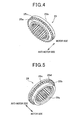
- the 2nd internal gear 29 has an inner diameter larger than the 1st internal gear 25, and has a higher number of teeth. As shown in Fig. 5 , the 2nd internal gear 29 is provided with an annular concave part 29a formed on the motor side of the 2nd internal gear 29 with the inner diameter larger than the diameter of teeth bottom of the 2nd internal gear 29.
- the annular concave part 29a and the annular convex part 25a provided in the 1st internal gear 25 are rotatably in meshing engagement (refer to Figs. 2 , 4 and 5 ).
- the 2nd internal gear 29 has two sizes of outer diameters. There provided are a small diameter part 29b on the motor side and a large diameter part 29c on the anti-motor side of the 2nd internal gear 29. Pluralities of teeth part 29d are formed on all circumferences of the motor side of the large diameter part 29c.
- the teeth part 29d formed on the large diameter part 29c has the same number of teeth as the teeth part 25c formed on the large diameter part 25b of the 1st internal gear 25, and the diameters of the teeth bottom and teeth tip of both the teeth part 25c and the teeth part 29d are the same.
- the reduction ratio switching means is equipped with a gear-switching member 34, and an electromagnetic drive means (described later) for moving the gear-switching member 34 in the direction of an axis.
- the gear-switching member 34 is made of a ferromagnetic substance (for example, iron) magnetized by the electromagnet.
- the gear-switching member 34 has a ring shape arranged coaxially on the perimeter of two internal gears 25 and 29. The perimeter of the gear-switching member 34 fits into the inner circumference of the cylinder wall part 9a of the front housing 9 and its movement to the direction of the diameter is suppressed (centering), however it is allowed to slide along the axis.
- a rotation suppressing part 34a having a small inner diameter is formed on the motor side of the gear-switching member 34.
- a cylinder iron core part 34b having a large inner diameter is formed on the anti-motor side of the rotation suppressing part 34a.
- Pluralities of teeth parts 34c and 34d are formed in the inner circumference of the rotation suppressing part 34a, and the inner circumference of the cylinder iron core part 34b at all circumferences, respectively.
- a motor side half of the teeth part 34c formed in the inner circumference of the rotation suppressing part 34a engages to the teeth part 25c formed in the 1st internal gear 25 when the gear-switching member 34 has moved to the motor side, as shown in Fig. 2 .
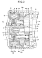
- An anti-motor side half of the teeth part 34c engages to the teeth part 29d formed in the 2nd internal gear 29 when the gear-switching member 34 has moved to the anti-motor side, as shown in Fig. 3 . That is, the teeth part 34c formed in the rotation suppressing part 34a is constituted by a 1st toothed part and a 2nd toothed part as a unit.
- the length in the axis direction of the teeth part 34c formed in the rotation suppressing part 34a is set to a little shorter than the distance in the axial direction of the space obtained between the teeth part 25c formed in the 1st internal gear 25 and the 2nd internal gear 29. That is, the teeth part 34c formed in rotation suppressing part 34a never engages with the teeth part 25c formed in the 1st internal gear 25 and the teeth part 29d in the 2nd internal gear 29 at the same time.
- the electromagnetic drive means comprises a magnetic coil 35, a yoke 36, and a return spring 37.
- the gear-switching member 34 engages mechanically with one of the 1st internal gear 25 and the 2nd internal gear 29.
- the magnetic coil 35 forms an electromagnet by energization and drives the gear-switching member 34 to the direction of anti-motor side by the attracting force of the electromagnet.
- the yoke 36 lets the magnetic flux generated by the magnetic coil 35 pass through.
- the return spring 37 pushes back the gear-switching member 34 to the direction of motor side when the energization to the magnetic coil 35 is stopped.
- the frame member 12 is constituted of ferromagnetic substances, such as iron, and forms a part of the magnetic path together with the yoke 36.
- the magnetic coil 35 is wound onto a bobbin 38 made of resin, and is arranged at the anti-motor side of the 2nd internal gear 29.
- the magnetic coil 35 is fixed to the frame member 12 via a projected part 38a provided in the bobbin 38.
- An end of the magnetic coil 35 pulled out from the exterior of the starter 1 is connected to the energization control means (for example, ECU, not shown), and ON (energization) and OFF (stop energization) is switched by a signal from the energization control means.
- the energization control means for example, ECU, not shown
- the energization control means may detect the outside air temperature, for example, directly or indirectly, and switches the ON/OFF state of the magnetic coil 35 depending on the detected outside air temperature.
- the energization control means switches the magnetic coil 35 OFF when the outside air temperature is above 0 degree centigrade, and switches the magnetic coil 35 ON when the outside air temperature is below 0 degree centigrade.
- the yoke 36 is comprised of a cylindrical magnetic path part 36a that forms a magnetic path in the inner circumference of the magnetic coil 35, and a ring-like magnetic path part 36b that forms the magnetic path in the motor side of the magnetic coil 35.
- the anti-motor side edge part of the cylindrical magnetic path part 36a fits and is fixed rotatably into the perimeter of a part with middle stage 12b provided in the frame member 12.
- the yoke 36 is arranged so that its axis matches the axis of the armature shaft 2b.
- pluralities of engagement slots 36c are formed along the direction of an axis in the inner circumference of the ring-like magnetic path part 36b.
- a part 36d is formed along the entire outer circumference of the ring-like magnetic path part 36b.
- a toothed ring 34d formed in the inner circumference of the cylinder iron core part 34b of the gear-switching member 34 engages to the teeth part 36d so that the ring-like magnetic path part 36b suppresses the relative rotation of the gear-switching member 34 in the direction of a circumference.
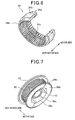
- FIG. 7 is the perspective diagram of the coil unit, which the magnetic coil 35 and the yoke 36 are attached to the frame member 12.
- the return spring 37 is arranged between the outer diameter part of the frame member 12 and a level difference formed in the perimeter of the gear-switching member 34. The return spring 37 pushes the gear-switching member 34 to the motor side.
- the gear-switching member 34 When the magnetic coil 35 is not energized, the gear-switching member 34 is pushed to the motor side by the force of the return spring 37, and the teeth part 34c formed in the rotation suppressing part 34a of the gear-switching member 34 engages with the teeth part 25c formed in the 1st internal gear 25.
- the impact-absorbing mechanism 8 is constituted with a plurality of (two, for example) rotating friction plates 39, a plurality of (two, for example) fixed friction plates 40, and a pressing means, or a plate spring 41 that presses the both plates 39 and 40 in between the frame member in the direction of an axis.
- the impact-absorbing mechanism 8 is arranged in the space defined by the perimeter of the bearing section 12a and the inner circumference of the cylindrical magnetic path part 36a of the yoke 36.
- the bearing section 12a of the frame member 12 is formed extending cylindrically from an end of the inner circumference of the frame member in the direction of the diameter to the direction of the motor side, and provided in the position that overlaps the cylindrical magnetic path part 36a of the yoke 36 in the direction of the axis.
- the rotating friction plate 39 is formed in a ring shape having a round hole 39a that is provided in the central part of the direction of a diameter, and a plurality of convex part 39b is formed on the perimeter thereof.
- the fixed friction plate 40 is formed in a ring shape having a center hole 40a, and a plurality of projection parts 40b and a plurality of fitting slots 40c are provided in the inner circumference of the center hole 40a.
- the projection parts 40b are projected to the one side of the direction of a thickness of the fixed friction plate 40, and their width in the direction of the circumference is formed in with two values; broad at the root side, and narrow at the tip side.
- the height of the projection the narrow part 40b2 having a narrower width in the direction of the circumference is approximately the same as the thickness of the fixed friction plate 40.
- FIG. 10A is a perspective diagram which shows the fixed friction plate 40 viewed from the other side (the side in which the projection parts 40b are not projected) in the direction of the plate thickness
- Fig. 10B is a perspective diagram which shows the fixed friction plate 40 from the one side (the side in which the projection parts 40b are projected) of the direction in the plate thickness.
- the inner diameter of the center hole 40a formed in the fixed friction plate 40 is formed almost the same in a size of the outer diameter of the bearing section 12a provided in the frame member 12 (however, the size is set so that the perimeter of the bearing section 12a can fit into the inner circumference of the center hole 40a).
- the size of the inner diameter with the size equivalent to twice the thickness of projection part 40b added to the diameter of the center hole 40a is formed almost equal to the inner diameter of the round hole 39a (however, the size is set so that the plurality of projection parts 40b are able to fit into the inner circumference of the round hole 39a).
- the fitting slots 40c are formed between the adjoining projection parts in the direction of the circumference, and are formed in the size that the narrow parts 40b2 of the projection parts 40b can fit exactly.
- the above-mentioned rotating friction plates 39 and fixed friction plates 40 are stacked, alternating one-by-one, and attached to the perimeter of bearing section 12a provided in the frame member 12.
- the friction plates 39 and 40 are pushed against the end surface of the frame member 12 in response to the load of the plate spring 41.
- both the frictions plates 39 and 40 are arranged from the frame member 12 side in the order of the rotating friction plate 39, the fixed friction plate 40, the rotating friction plate 39, and the fixed friction plate 40.
- the rotating friction plate 39 is rotatable to the frame member 12, and the relative rotation of both the rotating friction plate 39 and the frame member 12 is suppressed by concavo-convex fitting the convex part 39b provided in the perimeter to the engagement slots 36c formed in the inner circumference of the cylindrical magnetic path part 36a of the yoke 36.
- the rotation of the 1st fixed friction plate 40 that has the rotating friction plate 39 between the frame members 12 is suppressed by fitting the narrow part 40b2 of the projection part 40b into engaging slot 12c (refer to Fig. 8 ) formed in the frame member 12. Further, the rotation of the 2nd fixed friction plate 40 is suppressed by fitting the narrow part 40b2 of the projection part 40b into fitting slot40c formed in the 1st fixed friction plate 40.
- the plate spring 41 is fixed and caulked to the end of the bearing section 12a in the state where the slide torque of the rotating friction plate 39 is set as the predetermined sliding torque.
- the clutch 4 is pushed back as well by the shift movement of the shift lever 6 i.e., in the opposite direction for starting the engine.
- the pinion gear 5 is disengaged from the ring gear, and then returns back to the predetermined position (the position shown in Fig. 1 ) together with the clutch 4 on the output shaft 3 and stops.
- the rotation generated in the armature 2a is transmitted to the 1st planet gear 24 from the 1st sun gear 20, and while the 1st planet gear 24 rotates, it revolves the circumference of the 1st sun gear 20.
- the 2nd planet gear 28 since the rotation of the 2nd internal gear 29 is not suppressed (rotation is permitted), the 2nd planet gear 28 only rotates according to the rotation of the 2nd sun gear 21, and does not revolve around the 1st sun gear 20.
- revolution of the 2nd planet gear 28 is transmitted to the output shaft 3 from the planet carrier 30. That is, the rotation of the armature 2a is slowed down by the 2nd reduction ratio, and is transmitted to the output shaft 3.
- the torque and speed at the time of using the 1st speed reducer (the 1st reduction ratio) are shown in Fig. 11 by a solid line, and the torque and speed at the time of using the 2nd speed reducer (the 2nd reduction ratio) are shown in dashed line.
- the starter 1 of this embodiment since the 1st reduction ratio is used in temperature conditions higher than 0 degree centigrade, an output is set to P1, the speed is set to N1, the output and the speed improve sharply and shortening of starting time can be aimed for, compared to the case where the 2nd reduction ratio is used.
- the starter 1 of this embodiment since the 2nd reduction ratio is used in temperature conditions of 0 degree centigrade or less, the output becomes Pc, the speed becomes Nc, and it becomes the same operating point as conventional single reduction ratio. Thereby, the same good low-temperature starting nature as the former can be obtained.
- the shocking rotation load will be transmitted to the output axis 3 from the pinion gear 5, and will be further transmitted to the reduction gear from the output axis 3.
- gear-switching member 34 is connected with the rotating friction plate 39 of the impact-absorbing mechanism 8 via the yoke 36.
- the engagement of the tooth parts 36d formed in the ring-like magnetic path part 36b of the yoke 36 and the tooth parts 34d of the cylindrical iron core part 34b of the gear-switching member 34 suppresses the relative rotation of the both.
- the shock generated by the shocking rotation load is eased by the rotation load transmitted to the gear-switching member 34 being transmitted to the rotating friction plate 39 via a yoke 36, so that the rotating friction plate 39 rotates between the end surface of the frame member 12 and the fixed friction plate 40 with predetermined frictional resistance.
- the starter 1 of this embodiment is able to suppress reliably the rotation of the 1st internal gear 25 or the 2nd internal gear 29 by mechanical engagement (engagement of the teeth parts) to the gear-switching member 34.
- the starter 1 By moving the gear-switching member 34 in the direction of the axis, the starter 1 is also being able to change the reduction ratio by switching the internal gears 25 and 29 that suppress the rotation. According to this composition, since suppressing and canceling the suppression of the rotation of the two internal gears 25 and 29 can be performed in one gear-switching member 34, the number of parts can be reduced and the structure can be simplified.
- composition is to move the gear-switching member 34 in the direction of the axis for suppressing and canceling the suppression of the rotation of the two internal gears 25 and 29, and so it is not necessary to move the gear-switching member 34 radially, thus radial enlargement can be controlled.
- toothed parts are formed in the perimeter of the two internal gears 25 and 29 on the opposite side in the direction of the axle, respectively, for example, specifically, if toothed parts are formed in the perimeter of the 1st internal gear 25 on the direction of the motor side and in the perimeter of the 2nd internal gear 29 on the direction of the anti-motor side, respectively, it is necessary to detach and form the 1st toothed part and the 2nd toothed part in the direction of the axis on the gear-switching member 34.
- the 1st toothed part and the 2nd toothed part can be formed closely in the direction of the axis, and it is possible to shorten the length in the direction of the axis of the gear-switching member 34.
- Two internal gears 25 and 29 are arranged adjoining in the direction of the axis, and since the end surfaces of both internal gears 25 and 29 facing each other in the direction of the axis are engaged rotatably in concavo-convex manner, the axes of the both internal gears 25 and 29 can be matched.
- the magnetic coil 35 is used for the driving means of the gear-switching member 34 in this embodiment, the rotation of the internal gears 25 and 29 can be suppressed by a mechanical engagement of the gear-switching member 34 without depending on the power of attracting force of the magnetic coil 35, therefore the magnetic coil 35 can be miniaturized.
- the magnetic force generated by the magnetic coil 35 is needed only to attract the gear-switching member 34 in the direction of axis (the anti-motor direction), thus it is not necessary to suppress the rotation of the internal gears 25 and 29 by the attracting force of the magnetic coil 35, therefore the magnetic coil 35 can be miniaturized.
- the starter 1 being enlarged in the direction of the diameter is avoidable by arranging the miniaturized magnetic coil 35 adjoining to the 2nd internal gear 29 it in the direction of the axis.
- the relative rotation of the gear-switching member 34 is suppressed in by engaging the toothed ring 34d formed in the inner circumference of the cylinder iron core part 34b to the teeth part 36c formed in the perimeter of the ring-like magnetic path part 36b of the yoke 36. In this case, it is not necessary to newly provide any parts other than the yoke 36 in order to suppress the rotation of the gear-switching member 34, thus the increase in parts number can be controlled.
- the facing areas of the inner side of the cylinder iron core part 34b and the perimeter side of the ring-like magnetic path part 36b becomes large by forming the teeth parts 34d and 36c in the inner circumference of the cylinder iron core part 34b and the inner circumference of the ring-like magnetic path part 36b that face each other in the direction of the diameter, respectively, thus the magnetic resistance decreases and the attracting force of the magnetic coil 35 can be improved.
- the ON/OFF state of the magnetic coil 35 is selected according to the outside temperature in this embodiment, when outside air temperature is higher than 0 degree centigrade, the magnetic coil 35 is turned OFF and a small reduction ratio of the 1st reduction ratio is selected, for example, it is possible to shorten the engine starting time by increased speed of the starter 1 instead of selecting the 2nd reduction ratio.
- the frequency of using the 1st reduction ratio will increase rather than the 2nd reduction ratio in many areas on the earth, such as Japan, United States and Europe, for example.
- the electric energy needed to energize the magnetic coil 35 can be controlled to the minimum by turning OFF the magnetic coil 35 when selecting the frequently used 1st reduction ratio.
- the gear-switching member 34 is connected with the rotating friction plate 39 of the impact-absorbing mechanism 8 via the yoke 36, the power transfer system of the starter 1 can be protected when the excessive shock is applied to the internal gear (the 1st internal gear 25 or the 2nd internal gear 29) that engages with the gear-switching member 34 by the rotation of the rotating friction plate 39 that eases the shock.
- the impact-absorbing mechanism 8 it is possible to form the module of the reduction gear (the 1st internal gear 25 and the 2nd internal gear 29) used for two gear reduction systems smaller, and especially the outer diameter of the module can be miniaturized.
- the impact-absorbing mechanism 8 has a composition of having the rotating friction plate 39 and the fixed friction plate 40 stacked in the direction of their common axis, and is pressed in the direction of its axis with the plate spring 41, so that the parts are not disposed in the radial direction, so as not to increase the diameter of the starter 1, it is not necessary to secure a big loading space in the direction of the diameter, and the impact-absorbing mechanism 8 can be efficiently arranged in the space using the space defined by the cylindrical magnetic path part 36a of the yoke 36 and the bearing section 12a provided in the frame member 12.
- the space for arranging the impact-absorbing mechanism 8 is securable reasonably even if the starter 1 has two speed reduction systems and a reduction ratio changing means, the size of the starter 1 can be controlled not to become large.
- the impact-absorbing mechanism 8 can improve an impact-absorbing capability by increasing the number of plates that are used for the rotating friction plate 39 and the fixed friction plate 40, respectively.
- the big impact-absorbing mechanism 8 of impact-absorbing capability can be constituted compactly, without expanding the size of the direction of the axis sharply, since the impact-absorbing mechanism 8 is not enlarged in the direction of the diameter and both the frictions plates 39 and 40 are piled up in the direction of the plate thickness (the direction of the axis).
Landscapes
- Engineering & Computer Science (AREA)
- Chemical & Material Sciences (AREA)
- Combustion & Propulsion (AREA)
- Mechanical Engineering (AREA)
- General Engineering & Computer Science (AREA)
- Connection Of Motors, Electrical Generators, Mechanical Devices, And The Like (AREA)
- Structure Of Transmissions (AREA)
- Gear Transmission (AREA)
Applications Claiming Priority (1)
| Application Number | Priority Date | Filing Date | Title |
|---|---|---|---|
| JP2007265365A JP4831043B2 (ja) | 2007-10-11 | 2007-10-11 | スタータ |
Publications (3)
| Publication Number | Publication Date |
|---|---|
| EP2048356A2 true EP2048356A2 (de) | 2009-04-15 |
| EP2048356A3 EP2048356A3 (de) | 2010-05-19 |
| EP2048356B1 EP2048356B1 (de) | 2012-05-16 |
Family
ID=40219930
Family Applications (1)
| Application Number | Title | Priority Date | Filing Date |
|---|---|---|---|
| EP20080017844 Ceased EP2048356B1 (de) | 2007-10-11 | 2008-10-10 | Drehzahlreduktionsstarter für Motoren |
Country Status (2)
| Country | Link |
|---|---|
| EP (1) | EP2048356B1 (de) |
| JP (1) | JP4831043B2 (de) |
Cited By (3)
| Publication number | Priority date | Publication date | Assignee | Title |
|---|---|---|---|---|
| FR2969219A1 (fr) * | 2010-12-20 | 2012-06-22 | Valeo Equip Electr Moteur | Ensemble pour reducteur de vitesse d'une machine electrique tournante et demarreur pour moteur thermique associe |
| CN102536577A (zh) * | 2010-11-03 | 2012-07-04 | 通用汽车环球科技运作有限责任公司 | 多齿轮比起动器马达 |
| FR3034472A1 (fr) * | 2015-04-01 | 2016-10-07 | Peugeot Citroen Automobiles Sa | Dispositif de demarrage a double rapport de demultiplication |
Families Citing this family (4)
| Publication number | Priority date | Publication date | Assignee | Title |
|---|---|---|---|---|
| JP2015034596A (ja) * | 2013-08-08 | 2015-02-19 | 株式会社リコー | 速度変換装置及び画像形成装置 |
| JP6364974B2 (ja) * | 2014-06-04 | 2018-08-01 | 株式会社デンソー | エンジン始動装置 |
| JP2019138358A (ja) * | 2018-02-08 | 2019-08-22 | 株式会社オティックス | ギヤ装置 |
| KR102168510B1 (ko) * | 2019-01-14 | 2020-10-21 | 주식회사 피앤엔피 | 코일 밴드결속기의 밴드공급용 모터조립체 |
Citations (3)
| Publication number | Priority date | Publication date | Assignee | Title |
|---|---|---|---|---|
| JPS6128756A (ja) | 1984-07-18 | 1986-02-08 | Nippon Denso Co Ltd | 遊星歯車減速機構付スタ−タ |
| JPS61236951A (ja) | 1985-04-11 | 1986-10-22 | Kito Corp | 遊星歯車式2段変速装置を有する電動チェーンブロック |
| JPS61282650A (ja) | 1985-06-10 | 1986-12-12 | Takashi Takahashi | 遊星歯車機構 |
Family Cites Families (7)
| Publication number | Priority date | Publication date | Assignee | Title |
|---|---|---|---|---|
| FR2639413B1 (fr) * | 1988-11-18 | 1993-10-15 | Potain | Boite de vitesses a deux rapports et a changement de vitesse a l'arret |
| EP0582429A1 (de) * | 1992-08-06 | 1994-02-09 | Ford Motor Company | Verbundumlaufgetriebevorrichtung für Anlasser eines Verbrennungsmotors |
| US6409622B1 (en) * | 1998-11-14 | 2002-06-25 | Robert Bosch Gmbh | Electric motor with drive |
| JP3389921B2 (ja) * | 2000-09-21 | 2003-03-24 | 株式会社デンソー | スタータ |
| JP2004060520A (ja) * | 2002-07-29 | 2004-02-26 | Denso Corp | スタータ |
| JP2004218627A (ja) * | 2002-11-19 | 2004-08-05 | Denso Corp | 内燃機関用スタータ |
| JP2006118494A (ja) * | 2004-09-27 | 2006-05-11 | Denso Corp | スタータ |
-
2007
- 2007-10-11 JP JP2007265365A patent/JP4831043B2/ja not_active Expired - Fee Related
-
2008
- 2008-10-10 EP EP20080017844 patent/EP2048356B1/de not_active Ceased
Patent Citations (3)
| Publication number | Priority date | Publication date | Assignee | Title |
|---|---|---|---|---|
| JPS6128756A (ja) | 1984-07-18 | 1986-02-08 | Nippon Denso Co Ltd | 遊星歯車減速機構付スタ−タ |
| JPS61236951A (ja) | 1985-04-11 | 1986-10-22 | Kito Corp | 遊星歯車式2段変速装置を有する電動チェーンブロック |
| JPS61282650A (ja) | 1985-06-10 | 1986-12-12 | Takashi Takahashi | 遊星歯車機構 |
Cited By (6)
| Publication number | Priority date | Publication date | Assignee | Title |
|---|---|---|---|---|
| CN102536577A (zh) * | 2010-11-03 | 2012-07-04 | 通用汽车环球科技运作有限责任公司 | 多齿轮比起动器马达 |
| CN102536577B (zh) * | 2010-11-03 | 2015-06-03 | 通用汽车环球科技运作有限责任公司 | 多齿轮比起动器马达 |
| FR2969219A1 (fr) * | 2010-12-20 | 2012-06-22 | Valeo Equip Electr Moteur | Ensemble pour reducteur de vitesse d'une machine electrique tournante et demarreur pour moteur thermique associe |
| WO2012085424A1 (fr) * | 2010-12-20 | 2012-06-28 | Valeo Equipements Electriques Moteur | Ensemble pour reducteur de vitesse d'une machine electrique tournante et demarreur pour moteur thermique associe |
| US9309856B2 (en) | 2010-12-20 | 2016-04-12 | Valeo Equipements Electriques Moteur | Assembly for a speed reducer of a rotary electric machine, and related heat-engine starter |
| FR3034472A1 (fr) * | 2015-04-01 | 2016-10-07 | Peugeot Citroen Automobiles Sa | Dispositif de demarrage a double rapport de demultiplication |
Also Published As
| Publication number | Publication date |
|---|---|
| EP2048356A3 (de) | 2010-05-19 |
| JP2009092030A (ja) | 2009-04-30 |
| JP4831043B2 (ja) | 2011-12-07 |
| EP2048356B1 (de) | 2012-05-16 |
Similar Documents
| Publication | Publication Date | Title |
|---|---|---|
| EP2048356B1 (de) | Drehzahlreduktionsstarter für Motoren | |
| EP2006533B1 (de) | Motoranlasser | |
| JP4174820B2 (ja) | スタータ | |
| EP2011999B1 (de) | Drehzahlreduktionsstarter für Motoren | |
| JP4957530B2 (ja) | スタータ | |
| JP3603508B2 (ja) | スタータ | |
| EP2067985B1 (de) | Starter mit kompakter Struktur | |
| US5818118A (en) | Engine starter system having an improved pinion assembly | |
| CA2232912C (en) | A starter for an internal combustion engine | |
| US7194925B2 (en) | Starter | |
| CN100529380C (zh) | 具有支撑拨叉支点部分的可靠支点支架的起动机 | |
| JP5765974B2 (ja) | スタータ | |
| JP5115218B2 (ja) | スタータ | |
| EP0819847B1 (de) | Anlasser mit einer verbesserten Antriebs- und Rückstellvorrichtung des Ritzels | |
| JPH09170537A (ja) | スタータ | |
| JP2008255949A (ja) | スタータ | |
| JP2009036071A (ja) | エンジン始動装置 | |
| JP4957510B2 (ja) | スタータ | |
| JP4858358B2 (ja) | スタータ用緩衝装置 | |
| WO2013171876A1 (ja) | エンジン始動装置 | |
| JPH06351191A (ja) | 遊星歯車機構付きモータ | |
| JPH02275063A (ja) | スタータ | |
| JP2009036073A (ja) | エンジン始動装置 |
Legal Events
| Date | Code | Title | Description |
|---|---|---|---|
| PUAI | Public reference made under article 153(3) epc to a published international application that has entered the european phase |
Free format text: ORIGINAL CODE: 0009012 |
|
| AK | Designated contracting states |
Kind code of ref document: A2 Designated state(s): AT BE BG CH CY CZ DE DK EE ES FI FR GB GR HR HU IE IS IT LI LT LU LV MC MT NL NO PL PT RO SE SI SK TR |
|
| AX | Request for extension of the european patent |
Extension state: AL BA MK RS |
|
| PUAL | Search report despatched |
Free format text: ORIGINAL CODE: 0009013 |
|
| AK | Designated contracting states |
Kind code of ref document: A3 Designated state(s): AT BE BG CH CY CZ DE DK EE ES FI FR GB GR HR HU IE IS IT LI LT LU LV MC MT NL NO PL PT RO SE SI SK TR |
|
| AX | Request for extension of the european patent |
Extension state: AL BA MK RS |
|
| 17P | Request for examination filed |
Effective date: 20100916 |
|
| AKX | Designation fees paid |
Designated state(s): DE FR |
|
| GRAP | Despatch of communication of intention to grant a patent |
Free format text: ORIGINAL CODE: EPIDOSNIGR1 |
|
| RIC1 | Information provided on ipc code assigned before grant |
Ipc: F02N 11/00 20060101ALN20111018BHEP Ipc: F02N 15/06 20060101ALI20111018BHEP Ipc: F02N 15/04 20060101AFI20111018BHEP |
|
| RIN1 | Information on inventor provided before grant (corrected) |
Inventor name: NIIMI, MASAMI |
|
| RIC1 | Information provided on ipc code assigned before grant |
Ipc: F02N 15/06 20060101ALI20111031BHEP Ipc: F02N 11/00 20060101ALN20111031BHEP Ipc: F02N 15/04 20060101AFI20111031BHEP |
|
| GRAS | Grant fee paid |
Free format text: ORIGINAL CODE: EPIDOSNIGR3 |
|
| GRAA | (expected) grant |
Free format text: ORIGINAL CODE: 0009210 |
|
| AK | Designated contracting states |
Kind code of ref document: B1 Designated state(s): DE FR |
|
| REG | Reference to a national code |
Ref country code: DE Ref legal event code: R096 Ref document number: 602008015509 Country of ref document: DE Effective date: 20120712 |
|
| PLBE | No opposition filed within time limit |
Free format text: ORIGINAL CODE: 0009261 |
|
| STAA | Information on the status of an ep patent application or granted ep patent |
Free format text: STATUS: NO OPPOSITION FILED WITHIN TIME LIMIT |
|
| 26N | No opposition filed |
Effective date: 20130219 |
|
| REG | Reference to a national code |
Ref country code: DE Ref legal event code: R097 Ref document number: 602008015509 Country of ref document: DE Effective date: 20130219 |
|
| REG | Reference to a national code |
Ref country code: FR Ref legal event code: PLFP Year of fee payment: 8 |
|
| REG | Reference to a national code |
Ref country code: FR Ref legal event code: PLFP Year of fee payment: 9 |
|
| REG | Reference to a national code |
Ref country code: FR Ref legal event code: PLFP Year of fee payment: 10 |
|
| REG | Reference to a national code |
Ref country code: FR Ref legal event code: PLFP Year of fee payment: 11 |
|
| PGFP | Annual fee paid to national office [announced via postgrant information from national office to epo] |
Ref country code: DE Payment date: 20191021 Year of fee payment: 12 |
|
| PGFP | Annual fee paid to national office [announced via postgrant information from national office to epo] |
Ref country code: FR Payment date: 20191028 Year of fee payment: 12 |
|
| REG | Reference to a national code |
Ref country code: DE Ref legal event code: R119 Ref document number: 602008015509 Country of ref document: DE |
|
| PG25 | Lapsed in a contracting state [announced via postgrant information from national office to epo] |
Ref country code: DE Free format text: LAPSE BECAUSE OF NON-PAYMENT OF DUE FEES Effective date: 20210501 Ref country code: FR Free format text: LAPSE BECAUSE OF NON-PAYMENT OF DUE FEES Effective date: 20201031 |