EP2048407A1 - Verbesserte Energieabsorptionseinheit für Motorfahrzeug, die ein Plastikrohr umfasst, welches durch eine Rillenhalterung geführt wird, die bevorzugt durch Tiefziehen hergestellt wird - Google Patents
Verbesserte Energieabsorptionseinheit für Motorfahrzeug, die ein Plastikrohr umfasst, welches durch eine Rillenhalterung geführt wird, die bevorzugt durch Tiefziehen hergestellt wird Download PDFInfo
- Publication number
- EP2048407A1 EP2048407A1 EP08360028A EP08360028A EP2048407A1 EP 2048407 A1 EP2048407 A1 EP 2048407A1 EP 08360028 A EP08360028 A EP 08360028A EP 08360028 A EP08360028 A EP 08360028A EP 2048407 A1 EP2048407 A1 EP 2048407A1
- Authority
- EP
- European Patent Office
- Prior art keywords
- tube
- grooving
- kinetic energy
- guide sleeve
- absorber
- Prior art date
- Legal status (The legal status is an assumption and is not a legal conclusion. Google has not performed a legal analysis and makes no representation as to the accuracy of the status listed.)
- Granted
Links
- 239000004033 plastic Substances 0.000 title claims abstract description 38
- 229920003023 plastic Polymers 0.000 title claims abstract description 38
- 239000006096 absorbing agent Substances 0.000 title claims description 119
- 238000004519 manufacturing process Methods 0.000 claims abstract description 21
- 229910052751 metal Inorganic materials 0.000 claims description 22
- 239000002184 metal Substances 0.000 claims description 21
- 238000005520 cutting process Methods 0.000 claims description 19
- 239000000463 material Substances 0.000 claims description 15
- 230000035939 shock Effects 0.000 claims description 11
- 238000004080 punching Methods 0.000 claims description 6
- 230000000295 complement effect Effects 0.000 claims description 5
- 230000036346 tooth eruption Effects 0.000 claims description 5
- 239000004952 Polyamide Substances 0.000 claims description 3
- 229920002647 polyamide Polymers 0.000 claims description 3
- 238000010521 absorption reaction Methods 0.000 abstract description 12
- 238000000034 method Methods 0.000 abstract description 10
- BASFCYQUMIYNBI-UHFFFAOYSA-N platinum Chemical compound [Pt] BASFCYQUMIYNBI-UHFFFAOYSA-N 0.000 description 7
- 230000006870 function Effects 0.000 description 5
- 230000033001 locomotion Effects 0.000 description 5
- 238000003466 welding Methods 0.000 description 5
- -1 polypropylene Polymers 0.000 description 4
- 230000008569 process Effects 0.000 description 3
- 239000004743 Polypropylene Substances 0.000 description 2
- 229910052782 aluminium Inorganic materials 0.000 description 2
- XAGFODPZIPBFFR-UHFFFAOYSA-N aluminium Chemical compound [Al] XAGFODPZIPBFFR-UHFFFAOYSA-N 0.000 description 2
- 230000000712 assembly Effects 0.000 description 2
- 238000000429 assembly Methods 0.000 description 2
- 230000008901 benefit Effects 0.000 description 2
- 230000015572 biosynthetic process Effects 0.000 description 2
- 230000002860 competitive effect Effects 0.000 description 2
- 238000002788 crimping Methods 0.000 description 2
- 230000002093 peripheral effect Effects 0.000 description 2
- 239000005020 polyethylene terephthalate Substances 0.000 description 2
- 229920000139 polyethylene terephthalate Polymers 0.000 description 2
- 229920001155 polypropylene Polymers 0.000 description 2
- 238000010008 shearing Methods 0.000 description 2
- 229920000049 Carbon (fiber) Polymers 0.000 description 1
- 229910001018 Cast iron Inorganic materials 0.000 description 1
- 241000264877 Hippospongia communis Species 0.000 description 1
- BPQQTUXANYXVAA-UHFFFAOYSA-N Orthosilicate Chemical compound [O-][Si]([O-])([O-])[O-] BPQQTUXANYXVAA-UHFFFAOYSA-N 0.000 description 1
- 239000004698 Polyethylene Substances 0.000 description 1
- 240000008042 Zea mays Species 0.000 description 1
- 229910045601 alloy Inorganic materials 0.000 description 1
- 239000000956 alloy Substances 0.000 description 1
- 239000004917 carbon fiber Substances 0.000 description 1
- 238000005266 casting Methods 0.000 description 1
- 239000003795 chemical substances by application Substances 0.000 description 1
- 238000013016 damping Methods 0.000 description 1
- 230000007423 decrease Effects 0.000 description 1
- 230000003247 decreasing effect Effects 0.000 description 1
- 230000018109 developmental process Effects 0.000 description 1
- 238000009826 distribution Methods 0.000 description 1
- 238000001125 extrusion Methods 0.000 description 1
- 239000006260 foam Substances 0.000 description 1
- 239000003365 glass fiber Substances 0.000 description 1
- 230000006872 improvement Effects 0.000 description 1
- 238000002347 injection Methods 0.000 description 1
- 239000007924 injection Substances 0.000 description 1
- 238000001746 injection moulding Methods 0.000 description 1
- 239000010445 mica Substances 0.000 description 1
- 229910052618 mica group Inorganic materials 0.000 description 1
- 239000011859 microparticle Substances 0.000 description 1
- 239000000203 mixture Substances 0.000 description 1
- 238000012986 modification Methods 0.000 description 1
- 230000004048 modification Effects 0.000 description 1
- 238000000465 moulding Methods 0.000 description 1
- 229910052697 platinum Inorganic materials 0.000 description 1
- 229920000515 polycarbonate Polymers 0.000 description 1
- 239000004417 polycarbonate Substances 0.000 description 1
- 229920000573 polyethylene Polymers 0.000 description 1
- 239000004800 polyvinyl chloride Substances 0.000 description 1
- 238000003825 pressing Methods 0.000 description 1
- 230000002787 reinforcement Effects 0.000 description 1
- 230000003014 reinforcing effect Effects 0.000 description 1
- 230000004044 response Effects 0.000 description 1
- 238000007493 shaping process Methods 0.000 description 1
- 238000005245 sintering Methods 0.000 description 1
- 239000000454 talc Substances 0.000 description 1
- 229910052623 talc Inorganic materials 0.000 description 1
Images


Classifications
-
- B—PERFORMING OPERATIONS; TRANSPORTING
- B60—VEHICLES IN GENERAL
- B60R—VEHICLES, VEHICLE FITTINGS, OR VEHICLE PARTS, NOT OTHERWISE PROVIDED FOR
- B60R19/00—Wheel guards; Radiator guards, e.g. grilles; Obstruction removers; Fittings damping bouncing force in collisions
- B60R19/02—Bumpers, i.e. impact receiving or absorbing members for protecting vehicles or fending off blows from other vehicles or objects
- B60R19/24—Arrangements for mounting bumpers on vehicles
- B60R19/26—Arrangements for mounting bumpers on vehicles comprising yieldable mounting means
- B60R19/34—Arrangements for mounting bumpers on vehicles comprising yieldable mounting means destroyed upon impact, e.g. one-shot type
-
- F—MECHANICAL ENGINEERING; LIGHTING; HEATING; WEAPONS; BLASTING
- F16—ENGINEERING ELEMENTS AND UNITS; GENERAL MEASURES FOR PRODUCING AND MAINTAINING EFFECTIVE FUNCTIONING OF MACHINES OR INSTALLATIONS; THERMAL INSULATION IN GENERAL
- F16F—SPRINGS; SHOCK-ABSORBERS; MEANS FOR DAMPING VIBRATION
- F16F7/00—Vibration-dampers; Shock-absorbers
- F16F7/12—Vibration-dampers; Shock-absorbers using plastic deformation of members
- F16F7/125—Units with a telescopic-like action as one member moves into, or out of a second member
Definitions
- the present invention relates to an improved kinetic energy absorber assembly for a motor vehicle, in particular an automobile.
- This energy absorber assembly comprises a plastic absorber tube forced in advance through a grooving metal support preferably made in one piece by stamping.
- Motor vehicles are equipped with shields, also known as bumpers, whose main function is, in the event of a low-speed impact, to absorb the shock without damage in order to protect the vehicle, and, in the event of impact at greater speed, to dissipate all or part of the kinetic energy of the shock by deforming to prevent it being totally transmitted to the passenger compartment where the passengers are.
- shields also known as bumpers
- most current vehicles also include kinetic energy absorbing devices arranged at the rear of their shield to absorb some of the kinetic energy of the vehicle in a collision.
- These energy-absorbing devices are supplemented by zones of increasing deformation located at different locations of the vehicle, in particular at the level of the body panel and the structural side members, so that in case of impact all or a maximum of the kinetic energy is dissipated before arriving at the cockpit, thus protecting the passengers and avoiding significant damage to the vehicle.
- these kinetic energy absorbing devices must meet a large number of requirements, concerning their technical efficiency, in particular their response time and the amount of energy dissipated as a function of collision speed and speed. the angle of impact, but also concerning their size, their weight, their ease mounting and replacement, their stability to climatic conditions and especially their cost price.
- hydraulic damping devices For example, hydraulic damping devices, absorber devices with a deformable structure, in particular in the form of honeycombs, bellows or a metal tube possibly filled with aluminum foam, devices based on an alloy with shape memory, etc ...
- This device comprises a plastic tube secured to the rear of the shield. It also includes a grooving metal plate attached to the frame members of the vehicle frame via a flange of the plate.
- This metal plate is pierced with a central opening of generally circular shape whose diameter corresponds to the outer diameter of the plastic tube so as to fit the plate on the plastic tube.
- the edge of the central opening has teeth projecting into the opening of the opening.
- the plastic tube In the mounting position, the plastic tube is placed in front of the opening of the metal plate. In a collision with the vehicle bumper, the plastic tube is forced longitudinally through the central opening of the platen. During this movement the teeth of the platinum tear plastic chips on the surface of the tube, dissipating by this grooving operation a large amount of kinetic energy.
- a tubular guide sleeve secured to the front of the plate, can be optionally provided.
- the shock is inclined relative to the longitudinal axis of the tube and generates an oblique thrust force.
- some teeth penetrate too deeply into the tube and cut to the reinforcing insert located inside the plastic tube.
- the plastic tube tears, which blocks the entire system. In any case, a constant cutting effort can not be guaranteed over the entire stroke of the tube.
- the energy absorption is not optimal.
- the variant of this device comprising a guide sleeve at the front of the plate, works better from a practical point of view. However, for guidance to be properly achieved, the sleeve must be of sufficient length, at least 40 to 50 mm long.
- this sleeve located at the front of the plate, constitutes a stop for the beam of the shield and marks the end of the advance of the tube through the grooving plate and therefore the end of the absorption. energy.
- the presence of this sleeve decreases the race effective plastic tube and therefore the amount of energy that can be absorbed.
- the device ultimately obtained does not work properly or has a larger footprint than other systems known on the market.
- the object of the invention is to improve the prior device described in the application DE 102 43 460 to provide an improved, improved absorber assembly that can be economically manufactured and quite competitive.
- the invention teaches for this a more compact modified form, while ensuring satisfactory guidance of the plastic absorber tube. It also teaches an economical manufacturing process of this improved absorber assembly.
- the present invention makes the prior device attractive and competitive. It thus makes possible its industrial and commercial development, and consequently allows everyone to benefit from a system of very high efficiency, superior to other devices on the market.
- the invention provides a kinetic energy absorber assembly for a motor vehicle, in particular an automobile, comprising an absorber tube of which at least one outer layer is made of plastic and a metal grooving support carrying grooving elements. .
- the absorber tube is secured to a shock-absorbing member whose kinetic energy is to be absorbed and the grooving support is secured to a hollow-end structure element of the vehicle.
- the absorber tube and the grooving support are arranged so that in the event of a longitudinal impact, the absorber tube is forced forward through a central opening of the grooving support and the grooving elements pull plastic chips out of the groove. surface of the absorber tube, dissipating by this grooving operation at least a portion of the kinetic energy of the shock.
- the rear end of the absorber tube is initially engaged through the central opening and into the tubular guide sleeve of the grooving support.
- the absorber tube In case of longitudinal or inclined shock, the absorber tube is forced forward through the central opening and the tubular guide sleeve of the grooving support, the longitudinal projections tearing material chips plastic and digging longitudinal grooves in the side wall of the absorber tube.
- the side wall of the tubular guide sleeve is in guiding contact with substantially the entire outer surface of the side wall of the portion of the absorber tube engaged in the tubular guide sleeve and thus provides a tight guide of the advanced absorber tube.
- the kinetic energy absorber assembly according to the invention can be mounted at the rear of a vehicle shield, the absorber tube being secured to the beam of the shield and the grooving support. to a chassis frame of the vehicle.
- the kinetic energy absorber assembly according to the invention can be mounted for example on a hinge of the engine bonnet or at the level of the internal frame of a seat of the vehicle.
- the absorber assembly according to the invention is effective even when the axis of impact is oblique and is not entirely longitudinal, because of a particularly effective guiding exerted by the guide sleeve. which completely matches the shape of the side wall of the absorber tube portion engaged in the tubular guide sleeve.
- the absorber assembly according to the invention is also much more compact and allows to gain volume inside the vehicle, because the guide sleeve, located at the rear of the plate, is housed in the hollow end of the vehicle.
- a structural element of the vehicle for example the hollow end of a spar.
- the useful travel of the absorber tube is maximum and the cutting force is constant over the entire stroke, which provides a maximum energy absorption.
- the invention further provides a method of economic manufacture of such a kinetic energy absorber assembly wherein the grooving support is made in one piece, preferably by stamping from a sheet blank.
- front face of the device as being intended, in use, to be directed towards the shockable part, for example in the direction of the shield of the vehicle.
- the other directions will be defined accordingly.
- an assembly according to the invention may advantageously be used at the engine bonnet of a vehicle to absorb the energy of a possible impact with the head of a pedestrian.
- it will for example be placed in the hood hinges.
- One or more assemblies according to the invention can also be put in place in the seats of a vehicle, preferably at the internal frame of these seats, to absorb the energy developed by the passengers or objects projected against these seats. in case of collision of the vehicle.
- Motor vehicles are conventionally equipped, at the front and at the rear, with a shield consisting of a metal beam 1 which extends transversely to the vehicle, on which is reported a plastic skin, preferably polypropylene, constituting the bumper of the vehicle and may further include openings or supports for the vehicle optics, vents, and / or other elements techniques of diverse function.
- a shield consisting of a metal beam 1 which extends transversely to the vehicle, on which is reported a plastic skin, preferably polypropylene, constituting the bumper of the vehicle and may further include openings or supports for the vehicle optics, vents, and / or other elements techniques of diverse function.
- the beam 1 preferably formed of a stamped sheet metal or an aluminum profile, serves as stiffening reinforcement to the shield.
- this beam 1 is connected to the end of the longitudinal frame members 2 of the vehicle, which extend longitudinally over the entire length of the vehicle and support the body, by means of two energy absorber assemblies 3 according to the invention each interposed between the shield and one of the longitudinal members 2 of the motor vehicle, preferably automotive.
- each energy absorber assembly 3 is mounted on one side on the transverse beam 1 of the shield and on the other side on a chassis spar 2 of the vehicle.
- the energy absorber assembly 3 is formed of two independent parts: an absorber tube 4 and a grooving support 5, intended to cooperate with each other to achieve the desired kinetic energy absorption. in case of shock.
- a preferred embodiment of the absorber tube 4 has been shown alone on the figure 5 . It has a preferentially circular section, although other forms may also be envisaged, including an oval section or other. In this case, the grooving support 5 must be adapted accordingly.
- the absorber tube 4 comprises a layer outer plastic material, preferably in the form of an outer tube 6 of plastic material, of suitable dimensions to be able to cooperate with the grooving support 5 and perform the energy absorption function according to the invention.
- This outer layer or tube 6 is obtained by molding preferably by injection from any suitable plastics material.
- This is for example polyamide, polyvinyl chloride (PVC), polyethylene, polypropylene, polycarbonate, polyethylene terephthalate (PET) or other.
- plastics can also be a mixture of plastics or a filled plastic material, especially carbon fibers, glass fibers, talc, mica, silicate, metal microparticles or other.
- the choice of the material will depend on the technical characteristics that it is desired to obtain for the energy absorber assembly 3 according to the invention, the chip cutting resistance of the selected material influencing the amount of energy absorbed in case of shock.
- the outer layer is preferably made of polyamide which gives it satisfactory sliding properties facilitating its forced advancement movement through the grooving support 5.
- its thickness may be of the order of 6 to 10 mm, for an outer diameter of between 20 and 120 mm. Its length is preferably between 50 and 200 mm.
- the absorber tube 4 may be reinforced by a metal stiffening insert preferably in the form of an inner tube 7 on which the outer tube 6 is fitted. This metal insert stiffens the assembly and may optionally be used to carry out the fixing. from the absorber tube 4 to the beam 1 of the shield.
- this attachment may advantageously be via the inner tube 7 metal, for example by welding, screwing or other suitable means.
- This attachment is made at the front end 8 of the inner tube 7 which preferentially protrudes beyond the outer layer or tube 6.
- the absorber tube 4 preferably begins by fixing the inner tube 7 on the metal beam 1 of the shield. Then the outer tube 6 of plastic material is connected to the inner tube 7.
- the absorber tube 4 preferably has a set of longitudinal grooves 12 hollowed in its outer layer 6 and opening at the end of the tube but extending only over part of its length.
- grooves 12 allow the initial engagement of the rear end 11 of the absorber tube 4 in the grooving support 5. Their number, their location, their shape and their depth must of course be adapted and complementary to the corresponding grooving elements carried by the grooving support 5 which will now be described in detail.
- the grooving support 5 of the absorber assembly 3 according to the invention is a metal part which, as will be seen later, may advantageously be made in one piece by stamping.
- the grooving support 5, shown alone on the Figures 6 to 10 comprises a plate substantially flat, intended to be attached against a peripheral rim or an end plate 14 terminating each longitudinal frame 2 of the vehicle and to be secured thereto.
- the plate 13 of the grooving support 5 may have at the periphery a set of attachment openings 15, intended to cooperate with corresponding openings of an end plate 14 of the structural element, here the spar 2 to allow the passage of suitable fasteners such as for example a set of bolts 16.
- suitable fasteners such as for example a set of bolts 16.
- Other fastening means can obviously be envisaged as an alternative.
- the plate 13 of the grooving support 5 also has a central opening 17 of shape and dimensions adapted to those of the absorber tube 4 so that the latter can be introduced and pushed through this opening 17.
- the grooving support 5 also comprises a tubular guide sleeve 18 which extends at the rear of the plate 13 and whose hollow interior volume 19 is in the extension of the central opening 17.
- the shape and the dimensions of the hollow interior volume 19 of the tubular guide sleeve 18 substantially correspond to those of the outer tube 6 of the absorber tube 4, so that the side wall 20 of the tubular sleeve 18 exerts a tight guide of the absorber tube 4 when the it is pushed through the grooving support 5. Its length must also be sufficient for satisfactory guidance to be achieved. to be realized.
- the length of the tubular guide sleeve 18 is thus for example between 40 and 50 mm.
- the tubular guide sleeve 18 is substantially cylindrical and has an inside diameter substantially corresponding to the outside diameter of the absorber tube 4.
- the inner face of the side wall 20 of the tubular guide sleeve 18 has a series of longitudinal projections 21 extending longitudinally in the inner volume 19 of the guide sleeve 18 and preferably regularly distributed on this wall.
- these longitudinal projections 21 are deformations of the side wall 20 of the tubular guide sleeve 18.
- they have a rounded section, but may have any other form of adapted section, for example pointed, rectangular, trapezoidal or other.
- These longitudinal projections 21 constitute the grooving elements 22, also called knives, of the grooving support 5. Their number, their spacing and their dimensions must be chosen according to the amount of energy that it is desired to absorb.
- the height of these grooving elements 22 corresponds to the depth of the groove 12 which will be made in the absorber tube 4. It must therefore be adapted to the thickness of the outer tube 6 made of plastic material of the absorber tube 4. It may be by example of about 4 mm for a tube thickness of the order of 6 to 10 mm.
- the absorber assembly 3 has been shown assembled on the Figures 3 and 4 and mounted in use position on the vehicle on the Figures 1 and 2 .
- the grooving support 5 must be attached to the absorber tube 4 as illustrated in FIG. figure 3 .
- the fluted rear end 11 of the absorber tube 4 is engaged through the central opening 17 of the plate 13 of the grooving support 5 and sinks inside the guide sleeve 18 thereof.
- the longitudinal grooves 12 present on the rear end 11 of the absorber tube 4 are complementary to the grooving elements 22 projecting into the inner volume 19 of the guide sleeve 18. They thus allow the initial engagement, limited to its fluted portion, of the rear end 11 of the absorber tube 4 in the guide sleeve 18.
- the guide sleeve 18 of the grooving support 5 and the outer tube 6 of the absorber tube 4 have suitable dimensions and complementary shapes, so that the guide sleeve 18 perfectly matches the shape of the outer tube 6 and thus ensures tight guiding of it when it is forced forward through the grooving support 5 and this even if the thrust force exerted on the absorber tube 4 is not entirely longitudinal.
- the edge of the grooving elements 22 is preferably in abutment against the end wall 23 of the corresponding grooves 12.
- an energy absorber assembly 3 is put in place in the vehicle between the beam 1 of the shield and each of the frame members 2 of the vehicle.
- the absorber tube 4 is secured to the beam 1 at its front end 10 by any suitable means and on the other side, the grooving support 6 is fixed by its plate 13 to the spar 2.
- the guide sleeve 18 may advantageously be housed inside the hollow end of the spar 2, thus limiting the size of the device.
- the rear end of the inner metal tube 7 can be crimped to the rear of the tubular guide sleeve 18 of the groove carrier 5.
- a peripheral rim is formed at the end of the inner tube 7, which may optionally be completed by a washer previously inserted.
- This flange constitutes a rear stop opposing the withdrawal of the absorber tube 4 out of the grooving support 5.
- the beam 1 being fixed, in particular by welding, to the absorber tube 4 and the grooving support 5 being fixed by its plate to the spar 2, this crimping flange opposes any tensile force exerted on the beam 1 and ensures a fixation correct of the beam 1 to the spar 2.
- the shield In case of shock symbolized by the arrow 24, the shield is deformed and moves on its fasteners towards the longitudinal members 2.
- the absorber tube 4 which is secured to the beam 1 of the shield, is pushed towards the grooving support 5 fixed on the spar 2.
- the useful stroke of the absorber tube 4 that is to say the length of the forced advancement of the absorber tube 4 on which the chips 25 can be torn off and the energy absorption achieved in the event of impact, is maximum.
- this useful stroke corresponds to the entire free length of the absorber tube 4, the beam 1 can advance in the event of impact up against the plate 13 fixed to the end of the spar 2.
- the cutting force is constant over the entire stroke, and thus provides a maximum energy absorption.
- this energy absorption can be ensured even when the shock axis is oblique and non-longitudinal, because of a particularly effective guiding of the absorber tube 4 during its forced advancement, carried out by the guide sleeve 18.
- the side wall 20 of the sleeve 18 is not simply cylindrical, but has over substantially its entire length projections 21, the longitudinal side is thus in guiding contact with the whole of the outer surface of the tube splitter absorber 4 and not only with the still cylindrical part thereof, which allows it to ensure particularly effective tight guiding of the absorber tube 4.
- the amount of energy absorbable by the system can be optimized by adjusting several parameters: the length and the diameter of the absorber tube 4, the number, the size and the distribution of the grooving elements 22, the depth of the splines made.
- the improved energy absorber assembly 3 of the invention may be manufactured according to various manufacturing methods.
- the absorber tube 4 can be made for example by injection molding for its outer part made of plastic material.
- the grooving support 5 of metal can be made in one piece or in two independent parts: the plate 13 on the one hand and the guide sleeve 18 on the other hand, these two parts being assembled later.
- the guide sleeve 18 can thus for example be made by sintering and the plate 13 by punching, the two parts then being joined together preferably by welding.
- the grooving support 5 can also be made in one piece of cast iron by casting.
- the grooving support 5 is made of sheet metal by stamping.
- the grooving support 5 is made in one piece, which avoids the extra cost of an additional assembly step and in particular an additional welding step.
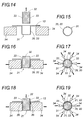
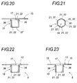
- a preferred example of a method of manufacturing a grooving support 5 according to the invention has been schematically represented on the Figures 11 to 23 .
- the grooving support 5 is manufactured in one piece by stamping.
- the sheet blank 26 is progressively deformed and stretched by a drawing punch 30 movable above the cavity 29 of the die 27 and gradually descending inside thereof.
- This punch 30 confers on the sheet blank 26 the shape of a cylindrical pot 31 corresponding to the general shape of the grooving support 5.
- stamping punches 30 of decreasing diameter and increasing stroke depth, as well as several matrices 27 with cavity 29 adapted.
- a large diameter punch descending only a shallow depth and with large radii of curvature at the bottom of the pot and at the level of the connection with the still flat portion of the sheet blank, and we finish with a punch 30 with the diameter, the stroke depth and the radii of curvature correspond to the shape to be obtained.
- the next step of the process, represented on Figures 14 to 18 consists in forming the longitudinal projections 21 which will serve as grooving elements 22.
- a counter-form 32 is introduced into the cylindrical pot 31.
- This against-shape 32 has a general cylinder shape whose dimensions correspond to those of the internal volume of the cylindrical pot 31, that is to say those of the inner volume 19 of the guide sleeve 18 to be obtained.
- the counter-form 32 comprises a series of longitudinal grooves 33 arranged opposite the location provided for the longitudinal projections 21 and whose shapes and dimensions are complementary to those of the longitudinal projections 21 to obtain.
- a series of wedges 34 of suitable shape is placed outside the cylindrical pot 31 facing each longitudinal groove 33. As shown in FIGS. Figures 16 to 19 each of these wedges 34 deforms the lateral wall 35 of the cylindrical pot 31, which will subsequently become the lateral wall 20 of the guide sleeve 18, by locally pressing it into the corresponding groove 33 of the counter-form 32, thus conforming the longitudinal projection 21 desired.
- a last stage of punching schematically on the figure 22 allows to cut the edge of the plate 13 to give it the desired shape and final dimensions. It also allows the simultaneous realization of the fixing apertures 15 in the plate 13. This gives the finished grooving support 5 shown on FIG. figure 23 .
- the steps of cutting the bottom 37 and punching the plate 13 can be performed simultaneously or independently of one another and in any order with respect to the 'other. In the same way, these two steps or one of these steps can or can be performed before the shaping operation of the longitudinal projections 21 by deformation and shearing of the side wall 35 of the cylindrical pot 31.
- the manufacturing method described above is particularly advantageous because it allows the grooving support 5 to be made from a blank of sheet metal 26 by stamping. This preferred process is particularly economical.
- the invention is in no way limited by it, the energy absorber assembly 3 according to the invention can be obtained by any other suitable manufacturing process to obtain the essential characteristics claimed.
- tubular guide sleeve 18 may comprise at the front a cylindrical engagement portion, located directly after the central opening 17 of the plate 13 and not having longitudinal projections 21, the longitudinal projections 21 starting only after this commitment portion.
- the absorber tube 4 may be entirely cylindrical and initially without a groove, its rear end 11 being engaged in mounting in the cylindrical engagement portion of the tubular guide sleeve 18.
- the outer tube 6 made of plastic material can then advantageously be made by extrusion.
- tubular guide sleeve 18 of the grooving support 5 may comprise, in addition to the longitudinal projections 21, a series of cutting teeth, originating at the rear end of the guide sleeve 18 and extending towards its interior volume 19.
- These cutting teeth are interposed between the longitudinal projections 21 and serve as additional grooving elements. They allow, at the outlet of the tubular guide sleeve 18, to cut chips in the still cylindrical areas of the absorber tube 4 between the grooves 12 hollowed by the longitudinal projections 21.
- the outer layer 6 of plastic material of the absorber tube 4 is thus exploited to the maximum and an additional amount of kinetic energy is dissipated as additional cutting energy.
- the cutting teeth of the tubular guide sleeve 18 can be formed very simply by cutting during the step of cutting the bottom 37 of the cylindrical pot 31 and simultaneously therewith.
Landscapes
- Engineering & Computer Science (AREA)
- Mechanical Engineering (AREA)
- General Engineering & Computer Science (AREA)
- Vibration Dampers (AREA)
- Arrangement Or Mounting Of Propulsion Units For Vehicles (AREA)
- Fluid-Damping Devices (AREA)
- Motor Power Transmission Devices (AREA)
- Vibration Prevention Devices (AREA)
- Blow-Moulding Or Thermoforming Of Plastics Or The Like (AREA)
Applications Claiming Priority (1)
| Application Number | Priority Date | Filing Date | Title |
|---|---|---|---|
| FR0707041A FR2921877B1 (fr) | 2007-10-08 | 2007-10-08 | Ensemble absorbeur d'energie ameliore pour vehicule a moteur, comprenant un tube en matiere plastique force a travers un support de rainurage preferentiellement realise par emboutissage |
Publications (2)
| Publication Number | Publication Date |
|---|---|
| EP2048407A1 true EP2048407A1 (de) | 2009-04-15 |
| EP2048407B1 EP2048407B1 (de) | 2010-11-03 |
Family
ID=39301264
Family Applications (1)
| Application Number | Title | Priority Date | Filing Date |
|---|---|---|---|
| EP08360028A Ceased EP2048407B1 (de) | 2007-10-08 | 2008-09-05 | Verbesserte Energieabsorptionseinheit für ein Motorfahrzeug, die ein Plastikrohr umfasst, welches durch eine Rillenhalterung geführt wird, die bevorzugt durch Tiefziehen hergestellt wird |
Country Status (4)
| Country | Link |
|---|---|
| EP (1) | EP2048407B1 (de) |
| AT (1) | ATE487067T1 (de) |
| DE (1) | DE602008003284D1 (de) |
| FR (1) | FR2921877B1 (de) |
Cited By (11)
| Publication number | Priority date | Publication date | Assignee | Title |
|---|---|---|---|---|
| WO2012016723A1 (de) * | 2010-08-06 | 2012-02-09 | Voith Patent Gmbh | ENERGIEVERZEHRVORRICHTUNG INSBESONDERE FÜR EINE STOßSICHERUNG EINES SPURGEFÜHRTEN FAHRZEUGES |
| CN104787078A (zh) * | 2015-04-22 | 2015-07-22 | 深圳市乾行达科技有限公司 | 一种组合式轨道交通车辆防爬器 |
| CN105000029A (zh) * | 2015-08-04 | 2015-10-28 | 深圳市乾行达科技有限公司 | 一种蜂窝芯内置的金属管-蜂窝芯复合式防爬器 |
| CN105292164A (zh) * | 2015-10-16 | 2016-02-03 | 中南大学 | 伸缩式轨道车辆碰撞吸能装置 |
| US9598033B1 (en) | 2015-11-09 | 2017-03-21 | United States Council For Automotive Research, Llc | Joining and reinforcing a composite bumper beam and a composite crush can for a vehicle |
| CN111350815A (zh) * | 2018-12-20 | 2020-06-30 | 罗伯特·博世有限公司 | 电磁操纵装置 |
| CN111469789A (zh) * | 2020-04-30 | 2020-07-31 | 中国飞机强度研究所 | 一种组合式碰撞吸能结构及其应用方法 |
| CN113028894A (zh) * | 2021-03-04 | 2021-06-25 | 北京理工大学 | 一种弹射装置的级间缓冲器 |
| WO2021197809A1 (de) * | 2020-03-30 | 2021-10-07 | Brose Fahrzeugteile SE & Co. Kommanditgesellschaft, Coburg | Sitzschienenpaar zur längsverstellung eines fahrzeugsitzes sowie energieabsorber und verriegelungseinrichtung, insbesondere für ein solches sitzschienenpaar |
| CN118907169A (zh) * | 2024-09-20 | 2024-11-08 | 中车唐山机车车辆有限公司 | 防爬吸能装置及轨道车辆 |
| CN121134024A (zh) * | 2025-11-06 | 2025-12-16 | 南京航空航天大学 | 一种自适应载荷的航空器新型抗坠毁膨胀式吸能结构 |
Families Citing this family (4)
| Publication number | Priority date | Publication date | Assignee | Title |
|---|---|---|---|---|
| DE102017114376A1 (de) | 2017-06-28 | 2019-01-03 | Axtone S.A. | Gelenkanordnung für ein Drehgestell umfassend zumindest ein Deformationselement und ein Verfahren zur Energieumwandlung |
| DE102020102127A1 (de) | 2020-01-29 | 2021-07-29 | Dr. Ing. H.C. F. Porsche Aktiengesellschaft | Stützteil |
| CN111660972B (zh) * | 2020-06-17 | 2024-02-27 | 华侨大学 | 吸能盒及应用该吸能盒的汽车防撞结构 |
| CN115027523B (zh) * | 2022-06-02 | 2023-07-11 | 中车株洲电力机车有限公司 | 一种主动防护的多级吸能装置及吸能方法 |
Citations (3)
| Publication number | Priority date | Publication date | Assignee | Title |
|---|---|---|---|---|
| DE10145446A1 (de) * | 2000-09-14 | 2002-03-28 | Reynolds Aluminium Bv | Energieabsorbierende Konstruktion und damit versehenes Fahrzeug |
| DE10243460A1 (de) | 2002-09-19 | 2004-04-01 | Rehau Ag + Co. | Polymerer Energieabsorber für Kraftfahrzeuge und Stoßfängersystem |
| EP1486381A2 (de) * | 2003-06-13 | 2004-12-15 | Innotec Forschungs- und Entwicklungs-GmbH | Kraftfahrzeugstossfänger |
-
2007
- 2007-10-08 FR FR0707041A patent/FR2921877B1/fr not_active Expired - Fee Related
-
2008
- 2008-09-05 EP EP08360028A patent/EP2048407B1/de not_active Ceased
- 2008-09-05 DE DE602008003284T patent/DE602008003284D1/de active Active
- 2008-09-05 AT AT08360028T patent/ATE487067T1/de not_active IP Right Cessation
Patent Citations (3)
| Publication number | Priority date | Publication date | Assignee | Title |
|---|---|---|---|---|
| DE10145446A1 (de) * | 2000-09-14 | 2002-03-28 | Reynolds Aluminium Bv | Energieabsorbierende Konstruktion und damit versehenes Fahrzeug |
| DE10243460A1 (de) | 2002-09-19 | 2004-04-01 | Rehau Ag + Co. | Polymerer Energieabsorber für Kraftfahrzeuge und Stoßfängersystem |
| EP1486381A2 (de) * | 2003-06-13 | 2004-12-15 | Innotec Forschungs- und Entwicklungs-GmbH | Kraftfahrzeugstossfänger |
Non-Patent Citations (1)
| Title |
|---|
| NEITZEL MANFRED: "IVW - Schriftenreihe", vol. BAND 9, 2000, INSTITUT FÜR VERBUNDWEKSTOFFE GMBH, KAISERSLAUTERN, XP003024373 |
Cited By (18)
| Publication number | Priority date | Publication date | Assignee | Title |
|---|---|---|---|---|
| WO2012016723A1 (de) * | 2010-08-06 | 2012-02-09 | Voith Patent Gmbh | ENERGIEVERZEHRVORRICHTUNG INSBESONDERE FÜR EINE STOßSICHERUNG EINES SPURGEFÜHRTEN FAHRZEUGES |
| CN104787078A (zh) * | 2015-04-22 | 2015-07-22 | 深圳市乾行达科技有限公司 | 一种组合式轨道交通车辆防爬器 |
| CN104787078B (zh) * | 2015-04-22 | 2017-08-29 | 深圳市乾行达科技有限公司 | 一种组合式轨道交通车辆防爬器 |
| CN105000029A (zh) * | 2015-08-04 | 2015-10-28 | 深圳市乾行达科技有限公司 | 一种蜂窝芯内置的金属管-蜂窝芯复合式防爬器 |
| CN105292164A (zh) * | 2015-10-16 | 2016-02-03 | 中南大学 | 伸缩式轨道车辆碰撞吸能装置 |
| RU2667998C1 (ru) * | 2015-10-16 | 2018-09-25 | Сентрал Саус Юниверсити | Телескопическое устройство, поглощающее энергию при столкновении на железнодорожном транспорте |
| US9598033B1 (en) | 2015-11-09 | 2017-03-21 | United States Council For Automotive Research, Llc | Joining and reinforcing a composite bumper beam and a composite crush can for a vehicle |
| CN111350815B (zh) * | 2018-12-20 | 2023-03-14 | 罗伯特·博世有限公司 | 电磁操纵装置 |
| CN111350815A (zh) * | 2018-12-20 | 2020-06-30 | 罗伯特·博世有限公司 | 电磁操纵装置 |
| WO2021197809A1 (de) * | 2020-03-30 | 2021-10-07 | Brose Fahrzeugteile SE & Co. Kommanditgesellschaft, Coburg | Sitzschienenpaar zur längsverstellung eines fahrzeugsitzes sowie energieabsorber und verriegelungseinrichtung, insbesondere für ein solches sitzschienenpaar |
| CN115362082A (zh) * | 2020-03-30 | 2022-11-18 | 博泽科堡汽车零件欧洲两合公司 | 用于车辆座椅的纵向调节的座椅导轨副以及特别是用于这种座椅导轨副的能量吸收器和锁定装置 |
| CN115362082B (zh) * | 2020-03-30 | 2023-09-01 | 博泽科堡汽车零件欧洲两合公司 | 用于车辆座椅的纵向调节的座椅导轨副以及特别是用于这种座椅导轨副的能量吸收器和锁定装置 |
| US12151595B2 (en) | 2020-03-30 | 2024-11-26 | Brose Fahrzeugteile SE & Co. Kommanditgesellschaft, Coburg | Seat rail pair for longitudinal adjustment of a vehicle seat and energy absorber and locking device, in particular for such a seat rail pair |
| CN111469789A (zh) * | 2020-04-30 | 2020-07-31 | 中国飞机强度研究所 | 一种组合式碰撞吸能结构及其应用方法 |
| CN111469789B (zh) * | 2020-04-30 | 2023-06-23 | 中国飞机强度研究所 | 一种组合式碰撞吸能结构及其应用方法 |
| CN113028894A (zh) * | 2021-03-04 | 2021-06-25 | 北京理工大学 | 一种弹射装置的级间缓冲器 |
| CN118907169A (zh) * | 2024-09-20 | 2024-11-08 | 中车唐山机车车辆有限公司 | 防爬吸能装置及轨道车辆 |
| CN121134024A (zh) * | 2025-11-06 | 2025-12-16 | 南京航空航天大学 | 一种自适应载荷的航空器新型抗坠毁膨胀式吸能结构 |
Also Published As
| Publication number | Publication date |
|---|---|
| FR2921877A1 (fr) | 2009-04-10 |
| EP2048407B1 (de) | 2010-11-03 |
| ATE487067T1 (de) | 2010-11-15 |
| DE602008003284D1 (de) | 2010-12-16 |
| FR2921877B1 (fr) | 2010-03-12 |
Similar Documents
| Publication | Publication Date | Title |
|---|---|---|
| EP2048407B1 (de) | Verbesserte Energieabsorptionseinheit für ein Motorfahrzeug, die ein Plastikrohr umfasst, welches durch eine Rillenhalterung geführt wird, die bevorzugt durch Tiefziehen hergestellt wird | |
| EP2091790B1 (de) | Auskleidung für die motorhaube eines fahrzeuges und kombinationen daraus mit bestimmten fahrzeugteilen | |
| EP1893469B1 (de) | Geführter unterbereich der front eines automobils | |
| EP2135775B1 (de) | Stoßstangenanordnung und entsprechendes Kraftfahrzeug | |
| FR3039476A1 (fr) | Support de choc pour porte, en particulier d'un vehicule automobile | |
| EP1878621B1 (de) | Kraftfahrzeugstoßstange insbesondere für Kombiwagen | |
| EP1595749B1 (de) | Verfahren zur Erstellung einer Trägerplatte einer energieabsorbierenden Stossstange und durch dieses Verfahren erhaltene Trägerplatte | |
| EP3016820B1 (de) | Kraftfahrzeugscheinwerfer | |
| EP3286028B1 (de) | Extrudierte verstärkungsträger mit präparierter verformung | |
| EP1957313B1 (de) | Kraftfahrzeugteil mit mitteln zum stützen eines optischen blocks | |
| EP0652388B1 (de) | Stossdämpfer | |
| EP3820743A1 (de) | Aus einem stück expandiertem polymermaterial mit stossabsorbierenden zonen hergestellte luftführung für ein kraftfahrzeug | |
| EP0687831B1 (de) | Perfektionierter Energiedämpfer für Kraftfahrzeug | |
| EP2867097B1 (de) | Kraftfahrzeug mit einem zusatzbewehrungsteil zur anleitung der verformung der zentralen säulenstruktur bei einem seitenaufprall | |
| EP1972527A1 (de) | Verstärkte Motorschutzverkleidung für Fahrzeug | |
| EP2819912A1 (de) | Kraftfahrzeug-wasserbehälter zur absorption eines teils der energie eines fussgängeraufpralls und entsprechende frontstruktur | |
| FR3072322A1 (fr) | Piece en materiau composite avec insert metallique | |
| EP3986772B1 (de) | Fahrzeugflügel mit schmelzbarem bereich für programmierte verformung | |
| WO2019068984A1 (fr) | Fusibilitee programmee du garnissage de porte | |
| FR3143484A1 (fr) | Dispositif absorbeur d’énergie | |
| EP4565440A1 (de) | Seitentür mit einer eine plattenverstärkung für ein fahrzeug abdeckenden rahmenverstärkung | |
| FR3142128A1 (fr) | Panneau de porte pour véhicule automobile comportant un renfort mécanique réalisé par impression additive | |
| EP3199409B1 (de) | Formelement eines belüftungsgitters für die frontseite eines kraftfahrzeugs | |
| FR3074461A1 (fr) | Ensemble absorbeur d'energie ameliore pour vehicule | |
| WO2015177422A2 (fr) | Structure de porte de véhicule automobile a armature creuse en plastique |
Legal Events
| Date | Code | Title | Description |
|---|---|---|---|
| PUAI | Public reference made under article 153(3) epc to a published international application that has entered the european phase |
Free format text: ORIGINAL CODE: 0009012 |
|
| AK | Designated contracting states |
Kind code of ref document: A1 Designated state(s): AT BE BG CH CY CZ DE DK EE ES FI FR GB GR HR HU IE IS IT LI LT LU LV MC MT NL NO PL PT RO SE SI SK TR |
|
| AX | Request for extension of the european patent |
Extension state: AL BA MK RS |
|
| 17P | Request for examination filed |
Effective date: 20090706 |
|
| AKX | Designation fees paid |
Designated state(s): AT BE BG CH CY CZ DE DK EE ES FI FR GB GR HR HU IE IS IT LI LT LU LV MC MT NL NO PL PT RO SE SI SK TR |
|
| GRAP | Despatch of communication of intention to grant a patent |
Free format text: ORIGINAL CODE: EPIDOSNIGR1 |
|
| GRAS | Grant fee paid |
Free format text: ORIGINAL CODE: EPIDOSNIGR3 |
|
| GRAA | (expected) grant |
Free format text: ORIGINAL CODE: 0009210 |
|
| AK | Designated contracting states |
Kind code of ref document: B1 Designated state(s): AT BE BG CH CY CZ DE DK EE ES FI FR GB GR HR HU IE IS IT LI LT LU LV MC MT NL NO PL PT RO SE SI SK TR |
|
| REG | Reference to a national code |
Ref country code: GB Ref legal event code: FG4D Free format text: NOT ENGLISH |
|
| REG | Reference to a national code |
Ref country code: CH Ref legal event code: EP |
|
| REG | Reference to a national code |
Ref country code: IE Ref legal event code: FG4D Free format text: LANGUAGE OF EP DOCUMENT: FRENCH |
|
| REF | Corresponds to: |
Ref document number: 602008003284 Country of ref document: DE Date of ref document: 20101216 Kind code of ref document: P |
|
| TPAC | Observations filed by third parties |
Free format text: ORIGINAL CODE: EPIDOSNTIPA |
|
| REG | Reference to a national code |
Ref country code: NL Ref legal event code: VDEP Effective date: 20101103 |
|
| LTIE | Lt: invalidation of european patent or patent extension |
Effective date: 20101103 |
|
| PG25 | Lapsed in a contracting state [announced via postgrant information from national office to epo] |
Ref country code: NO Free format text: LAPSE BECAUSE OF FAILURE TO SUBMIT A TRANSLATION OF THE DESCRIPTION OR TO PAY THE FEE WITHIN THE PRESCRIBED TIME-LIMIT Effective date: 20110203 Ref country code: LT Free format text: LAPSE BECAUSE OF FAILURE TO SUBMIT A TRANSLATION OF THE DESCRIPTION OR TO PAY THE FEE WITHIN THE PRESCRIBED TIME-LIMIT Effective date: 20101103 |
|
| REG | Reference to a national code |
Ref country code: IE Ref legal event code: FD4D |
|
| PG25 | Lapsed in a contracting state [announced via postgrant information from national office to epo] |
Ref country code: SE Free format text: LAPSE BECAUSE OF FAILURE TO SUBMIT A TRANSLATION OF THE DESCRIPTION OR TO PAY THE FEE WITHIN THE PRESCRIBED TIME-LIMIT Effective date: 20101103 Ref country code: BG Free format text: LAPSE BECAUSE OF FAILURE TO SUBMIT A TRANSLATION OF THE DESCRIPTION OR TO PAY THE FEE WITHIN THE PRESCRIBED TIME-LIMIT Effective date: 20110203 Ref country code: LV Free format text: LAPSE BECAUSE OF FAILURE TO SUBMIT A TRANSLATION OF THE DESCRIPTION OR TO PAY THE FEE WITHIN THE PRESCRIBED TIME-LIMIT Effective date: 20101103 Ref country code: HR Free format text: LAPSE BECAUSE OF FAILURE TO SUBMIT A TRANSLATION OF THE DESCRIPTION OR TO PAY THE FEE WITHIN THE PRESCRIBED TIME-LIMIT Effective date: 20101103 Ref country code: SI Free format text: LAPSE BECAUSE OF FAILURE TO SUBMIT A TRANSLATION OF THE DESCRIPTION OR TO PAY THE FEE WITHIN THE PRESCRIBED TIME-LIMIT Effective date: 20101103 Ref country code: IS Free format text: LAPSE BECAUSE OF FAILURE TO SUBMIT A TRANSLATION OF THE DESCRIPTION OR TO PAY THE FEE WITHIN THE PRESCRIBED TIME-LIMIT Effective date: 20110303 Ref country code: PT Free format text: LAPSE BECAUSE OF FAILURE TO SUBMIT A TRANSLATION OF THE DESCRIPTION OR TO PAY THE FEE WITHIN THE PRESCRIBED TIME-LIMIT Effective date: 20110303 Ref country code: FI Free format text: LAPSE BECAUSE OF FAILURE TO SUBMIT A TRANSLATION OF THE DESCRIPTION OR TO PAY THE FEE WITHIN THE PRESCRIBED TIME-LIMIT Effective date: 20101103 Ref country code: NL Free format text: LAPSE BECAUSE OF FAILURE TO SUBMIT A TRANSLATION OF THE DESCRIPTION OR TO PAY THE FEE WITHIN THE PRESCRIBED TIME-LIMIT Effective date: 20101103 Ref country code: AT Free format text: LAPSE BECAUSE OF FAILURE TO SUBMIT A TRANSLATION OF THE DESCRIPTION OR TO PAY THE FEE WITHIN THE PRESCRIBED TIME-LIMIT Effective date: 20101103 |
|
| PG25 | Lapsed in a contracting state [announced via postgrant information from national office to epo] |
Ref country code: GR Free format text: LAPSE BECAUSE OF FAILURE TO SUBMIT A TRANSLATION OF THE DESCRIPTION OR TO PAY THE FEE WITHIN THE PRESCRIBED TIME-LIMIT Effective date: 20110204 |
|
| PG25 | Lapsed in a contracting state [announced via postgrant information from national office to epo] |
Ref country code: ES Free format text: LAPSE BECAUSE OF FAILURE TO SUBMIT A TRANSLATION OF THE DESCRIPTION OR TO PAY THE FEE WITHIN THE PRESCRIBED TIME-LIMIT Effective date: 20110214 Ref country code: CZ Free format text: LAPSE BECAUSE OF FAILURE TO SUBMIT A TRANSLATION OF THE DESCRIPTION OR TO PAY THE FEE WITHIN THE PRESCRIBED TIME-LIMIT Effective date: 20101103 Ref country code: EE Free format text: LAPSE BECAUSE OF FAILURE TO SUBMIT A TRANSLATION OF THE DESCRIPTION OR TO PAY THE FEE WITHIN THE PRESCRIBED TIME-LIMIT Effective date: 20101103 Ref country code: IE Free format text: LAPSE BECAUSE OF FAILURE TO SUBMIT A TRANSLATION OF THE DESCRIPTION OR TO PAY THE FEE WITHIN THE PRESCRIBED TIME-LIMIT Effective date: 20101103 |
|
| PG25 | Lapsed in a contracting state [announced via postgrant information from national office to epo] |
Ref country code: SK Free format text: LAPSE BECAUSE OF FAILURE TO SUBMIT A TRANSLATION OF THE DESCRIPTION OR TO PAY THE FEE WITHIN THE PRESCRIBED TIME-LIMIT Effective date: 20101103 Ref country code: DK Free format text: LAPSE BECAUSE OF FAILURE TO SUBMIT A TRANSLATION OF THE DESCRIPTION OR TO PAY THE FEE WITHIN THE PRESCRIBED TIME-LIMIT Effective date: 20101103 Ref country code: RO Free format text: LAPSE BECAUSE OF FAILURE TO SUBMIT A TRANSLATION OF THE DESCRIPTION OR TO PAY THE FEE WITHIN THE PRESCRIBED TIME-LIMIT Effective date: 20101103 Ref country code: PL Free format text: LAPSE BECAUSE OF FAILURE TO SUBMIT A TRANSLATION OF THE DESCRIPTION OR TO PAY THE FEE WITHIN THE PRESCRIBED TIME-LIMIT Effective date: 20101103 |
|
| PLBE | No opposition filed within time limit |
Free format text: ORIGINAL CODE: 0009261 |
|
| STAA | Information on the status of an ep patent application or granted ep patent |
Free format text: STATUS: NO OPPOSITION FILED WITHIN TIME LIMIT |
|
| 26N | No opposition filed |
Effective date: 20110804 |
|
| REG | Reference to a national code |
Ref country code: DE Ref legal event code: R097 Ref document number: 602008003284 Country of ref document: DE Effective date: 20110804 |
|
| PG25 | Lapsed in a contracting state [announced via postgrant information from national office to epo] |
Ref country code: IT Free format text: LAPSE BECAUSE OF FAILURE TO SUBMIT A TRANSLATION OF THE DESCRIPTION OR TO PAY THE FEE WITHIN THE PRESCRIBED TIME-LIMIT Effective date: 20101103 |
|
| BERE | Be: lapsed |
Owner name: REHAU SA Effective date: 20110930 |
|
| PG25 | Lapsed in a contracting state [announced via postgrant information from national office to epo] |
Ref country code: MC Free format text: LAPSE BECAUSE OF NON-PAYMENT OF DUE FEES Effective date: 20110930 |
|
| PG25 | Lapsed in a contracting state [announced via postgrant information from national office to epo] |
Ref country code: BE Free format text: LAPSE BECAUSE OF NON-PAYMENT OF DUE FEES Effective date: 20110930 |
|
| PG25 | Lapsed in a contracting state [announced via postgrant information from national office to epo] |
Ref country code: MT Free format text: LAPSE BECAUSE OF FAILURE TO SUBMIT A TRANSLATION OF THE DESCRIPTION OR TO PAY THE FEE WITHIN THE PRESCRIBED TIME-LIMIT Effective date: 20101103 |
|
| REG | Reference to a national code |
Ref country code: CH Ref legal event code: PL |
|
| GBPC | Gb: european patent ceased through non-payment of renewal fee |
Effective date: 20120905 |
|
| PG25 | Lapsed in a contracting state [announced via postgrant information from national office to epo] |
Ref country code: CY Free format text: LAPSE BECAUSE OF EXPIRATION OF PROTECTION Effective date: 20101103 Ref country code: LU Free format text: LAPSE BECAUSE OF NON-PAYMENT OF DUE FEES Effective date: 20110905 |
|
| PG25 | Lapsed in a contracting state [announced via postgrant information from national office to epo] |
Ref country code: CH Free format text: LAPSE BECAUSE OF NON-PAYMENT OF DUE FEES Effective date: 20120930 Ref country code: GB Free format text: LAPSE BECAUSE OF NON-PAYMENT OF DUE FEES Effective date: 20120905 Ref country code: LI Free format text: LAPSE BECAUSE OF NON-PAYMENT OF DUE FEES Effective date: 20120930 |
|
| PG25 | Lapsed in a contracting state [announced via postgrant information from national office to epo] |
Ref country code: TR Free format text: LAPSE BECAUSE OF FAILURE TO SUBMIT A TRANSLATION OF THE DESCRIPTION OR TO PAY THE FEE WITHIN THE PRESCRIBED TIME-LIMIT Effective date: 20101103 |
|
| PG25 | Lapsed in a contracting state [announced via postgrant information from national office to epo] |
Ref country code: HU Free format text: LAPSE BECAUSE OF FAILURE TO SUBMIT A TRANSLATION OF THE DESCRIPTION OR TO PAY THE FEE WITHIN THE PRESCRIBED TIME-LIMIT Effective date: 20101103 |
|
| REG | Reference to a national code |
Ref country code: FR Ref legal event code: PLFP Year of fee payment: 8 |
|
| REG | Reference to a national code |
Ref country code: FR Ref legal event code: PLFP Year of fee payment: 9 |
|
| REG | Reference to a national code |
Ref country code: FR Ref legal event code: PLFP Year of fee payment: 10 |
|
| REG | Reference to a national code |
Ref country code: FR Ref legal event code: PLFP Year of fee payment: 11 |
|
| PGFP | Annual fee paid to national office [announced via postgrant information from national office to epo] |
Ref country code: DE Payment date: 20180918 Year of fee payment: 11 Ref country code: FR Payment date: 20180926 Year of fee payment: 11 |
|
| REG | Reference to a national code |
Ref country code: DE Ref legal event code: R119 Ref document number: 602008003284 Country of ref document: DE |
|
| PG25 | Lapsed in a contracting state [announced via postgrant information from national office to epo] |
Ref country code: DE Free format text: LAPSE BECAUSE OF NON-PAYMENT OF DUE FEES Effective date: 20200401 |
|
| PG25 | Lapsed in a contracting state [announced via postgrant information from national office to epo] |
Ref country code: FR Free format text: LAPSE BECAUSE OF NON-PAYMENT OF DUE FEES Effective date: 20190930 |