EP2048447A2 - Panneau - Google Patents
Panneau Download PDFInfo
- Publication number
- EP2048447A2 EP2048447A2 EP08252936A EP08252936A EP2048447A2 EP 2048447 A2 EP2048447 A2 EP 2048447A2 EP 08252936 A EP08252936 A EP 08252936A EP 08252936 A EP08252936 A EP 08252936A EP 2048447 A2 EP2048447 A2 EP 2048447A2
- Authority
- EP
- European Patent Office
- Prior art keywords
- panel
- panel according
- grooves
- pipe
- floor
- Prior art date
- Legal status (The legal status is an assumption and is not a legal conclusion. Google has not performed a legal analysis and makes no representation as to the accuracy of the status listed.)
- Withdrawn
Links
- 239000012530 fluid Substances 0.000 claims abstract description 9
- 239000012080 ambient air Substances 0.000 claims abstract description 8
- 230000003750 conditioning effect Effects 0.000 claims abstract description 8
- 229910052751 metal Inorganic materials 0.000 claims description 31
- 239000002184 metal Substances 0.000 claims description 30
- 239000011888 foil Substances 0.000 claims description 17
- 239000000853 adhesive Substances 0.000 claims description 10
- 239000005030 aluminium foil Substances 0.000 claims description 8
- 238000010276 construction Methods 0.000 claims description 7
- 239000004795 extruded polystyrene foam Substances 0.000 claims description 6
- 239000004411 aluminium Substances 0.000 claims description 4
- 229910052782 aluminium Inorganic materials 0.000 claims description 4
- XAGFODPZIPBFFR-UHFFFAOYSA-N aluminium Chemical compound [Al] XAGFODPZIPBFFR-UHFFFAOYSA-N 0.000 claims description 4
- 239000004794 expanded polystyrene Substances 0.000 claims description 4
- 239000006261 foam material Substances 0.000 claims description 4
- 229920005830 Polyurethane Foam Polymers 0.000 claims description 3
- 230000001070 adhesive effect Effects 0.000 claims description 3
- 239000011810 insulating material Substances 0.000 claims description 3
- 238000003801 milling Methods 0.000 claims description 3
- 239000011496 polyurethane foam Substances 0.000 claims description 3
- 238000012546 transfer Methods 0.000 claims description 3
- 239000003973 paint Substances 0.000 claims description 2
- 230000001419 dependent effect Effects 0.000 claims 1
- 238000010438 heat treatment Methods 0.000 description 16
- XLYOFNOQVPJJNP-UHFFFAOYSA-N water Substances O XLYOFNOQVPJJNP-UHFFFAOYSA-N 0.000 description 6
- 238000001816 cooling Methods 0.000 description 4
- 238000013461 design Methods 0.000 description 3
- 238000009434 installation Methods 0.000 description 3
- 238000009413 insulation Methods 0.000 description 2
- 230000005855 radiation Effects 0.000 description 2
- 230000002787 reinforcement Effects 0.000 description 2
- 230000000295 complement effect Effects 0.000 description 1
- 239000002131 composite material Substances 0.000 description 1
- 230000000694 effects Effects 0.000 description 1
- 238000010616 electrical installation Methods 0.000 description 1
- 238000001125 extrusion Methods 0.000 description 1
- 229920002457 flexible plastic Polymers 0.000 description 1
- 238000007667 floating Methods 0.000 description 1
- 238000003780 insertion Methods 0.000 description 1
- 230000037431 insertion Effects 0.000 description 1
- 239000012212 insulator Substances 0.000 description 1
- 238000003754 machining Methods 0.000 description 1
- 239000000463 material Substances 0.000 description 1
- 238000000034 method Methods 0.000 description 1
- 238000012986 modification Methods 0.000 description 1
- 230000004048 modification Effects 0.000 description 1
- 238000010137 moulding (plastic) Methods 0.000 description 1
- 239000004033 plastic Substances 0.000 description 1
- 229920003023 plastic Polymers 0.000 description 1
- -1 polybutylene Polymers 0.000 description 1
- 229920001748 polybutylene Polymers 0.000 description 1
- 229920000573 polyethylene Polymers 0.000 description 1
- 229920006327 polystyrene foam Polymers 0.000 description 1
- 239000007787 solid Substances 0.000 description 1
- 239000002023 wood Substances 0.000 description 1
Images




Classifications
-
- F—MECHANICAL ENGINEERING; LIGHTING; HEATING; WEAPONS; BLASTING
- F24—HEATING; RANGES; VENTILATING
- F24D—DOMESTIC- OR SPACE-HEATING SYSTEMS, e.g. CENTRAL HEATING SYSTEMS; DOMESTIC HOT-WATER SUPPLY SYSTEMS; ELEMENTS OR COMPONENTS THEREFOR
- F24D3/00—Hot-water central heating systems
- F24D3/12—Tube and panel arrangements for ceiling, wall, or underfloor heating
- F24D3/14—Tube and panel arrangements for ceiling, wall, or underfloor heating incorporated in a ceiling, wall or floor
- F24D3/141—Tube mountings specially adapted therefor
- F24D3/142—Tube mountings specially adapted therefor integrated in prefab construction elements
-
- F—MECHANICAL ENGINEERING; LIGHTING; HEATING; WEAPONS; BLASTING
- F24—HEATING; RANGES; VENTILATING
- F24D—DOMESTIC- OR SPACE-HEATING SYSTEMS, e.g. CENTRAL HEATING SYSTEMS; DOMESTIC HOT-WATER SUPPLY SYSTEMS; ELEMENTS OR COMPONENTS THEREFOR
- F24D3/00—Hot-water central heating systems
- F24D3/12—Tube and panel arrangements for ceiling, wall, or underfloor heating
- F24D3/14—Tube and panel arrangements for ceiling, wall, or underfloor heating incorporated in a ceiling, wall or floor
- F24D3/148—Tube and panel arrangements for ceiling, wall, or underfloor heating incorporated in a ceiling, wall or floor with heat spreading plates
-
- Y—GENERAL TAGGING OF NEW TECHNOLOGICAL DEVELOPMENTS; GENERAL TAGGING OF CROSS-SECTIONAL TECHNOLOGIES SPANNING OVER SEVERAL SECTIONS OF THE IPC; TECHNICAL SUBJECTS COVERED BY FORMER USPC CROSS-REFERENCE ART COLLECTIONS [XRACs] AND DIGESTS
- Y02—TECHNOLOGIES OR APPLICATIONS FOR MITIGATION OR ADAPTATION AGAINST CLIMATE CHANGE
- Y02B—CLIMATE CHANGE MITIGATION TECHNOLOGIES RELATED TO BUILDINGS, e.g. HOUSING, HOUSE APPLIANCES OR RELATED END-USER APPLICATIONS
- Y02B30/00—Energy efficient heating, ventilation or air conditioning [HVAC]
Definitions
- the invention relates to a panel, particularly to a panel which is used in systems for heating and/or cooling a room or rooms of a building.
- radiators are often turned off in upstairs rooms, unless it is very cold outside, as sufficient heat is transmitted to upstairs rooms to maintain a reasonable temperature either by convection via staircases or conduction/radiation via the ground-floor ceiling and the floor on the upper floors. In principle, this also applies if the ground floor is heated by other means, e.g. radiators.
- Radiators are expensive items per se , cost time and money to install, and usually take up wall space which cannot therefore be used for other purposes.
- An object of the invention is therefore to seek to obviate the need for radiators, particularly in an upper room such as a bedroom of a building such as a house.
- a panel for use for condition ambient air in a room of a building characterised by a body, by a plurality of grooves in a major surface of the body and by a pipe adapted to carry conditioning fluid being mounted via respective portions of the pipe in the grooves so that at return positions of the pipe adjacent pipe portions cross-over.
- upper floor rooms such as bedrooms of a house can be heated from a conventional ground floor heating system.
- the body may comprise an insulating material which itself may comprise a foam material such as for example a polyurethane foam, expanded polystyrene or XPS.
- This provides a relatively simple yet efficient heat insulator.
- a heat transfer medium may be incorporated at or on the said surface. This provides for heating ambient air by conduction and/or convection particularly when the medium may comprise a metal plate or skin such as an aluminium heat spreader plate.
- the heat spreader plate may have a greater lateral extent at one or both sides than that of the body of the panel.
- This provides for "hanging" of a panel on a joist.
- the panel may also comprise a surface metal layer, and the grooves may be formed by routing or milling through the layer into the body. This provides a suitable and effective way to form the grooves.
- the medium may comprise the layer outside the grooves and an additional metal layer in each of the grooves.
- the additional metal layer may comprise a metal foil.
- the metal foil For effective location of the metal foil, it may be secured in place by an interference fit in the respective groove, or alternatively, the metal foil may be secured in place in the respective groove by adhesive.
- the medium may comprise the metal layer and a heat conductive paint or paste in each groove.
- a surface of the body directed in use away from the room interior may comprise means to obviate heat loss, said means preferably comprising a metal foil, such as an aluminium foil.
- the said surface may in use be a lower surface of the panel.
- the cross-over of the pipe portions may be inboard of the lateral extent or boundary of the body. Alternatively, the cross-over of the pipe portions may extend beyond the lateral extent or boundary of the body.
- Both constructions allow the pipe portions to be fitted very closely together whereby to achieve a high heat output from a small panel area.
- the panel may comprise a floor panel, a ceiling panel or a wall panel of a room of a building.
- the grooves may be substantially parallel over part of the body, and may have curved parts which cross-over to provide for cross-over of the pipe portions.
- the body may suitably comprise extruded polystyrene foam.
- the metal layer suitably comprising an aluminium foil, which in a preferred embodiment may comprise a self-adhesive foil. This provides for ease of the application to the body.
- the foil may also line the inside of the grooves so the pipe is in close contact therewith, the foil following the continuously complete profile of the top of the body in use.
- the body may comprise a panel, and may comprise at a major surface opposite from the grooves, indicia indicating the positions of the grooves.
- indicia indicating the positions of the grooves. This allows for securing of the panel to a joist etc. of a floor, wall or ceiling from below using securing means such as screws or nails with large diameter washers or heads.
- the indicia thus assists in avoiding puncturing of the pipe means by the securing means, so obviating leaks, but ensuring that the securing means is not aligned with a groove and hence a pipe therein.
- the body may alternatively comprise a plurality of spaced struts each comprising a groove or grooves.
- the pipe may be carrying a fluid adapted to be heated by surrounding medium, and may provide a geothermal device.
- a floor, wall or ceiling of a room of a building incorporating a panel as hereinbefore defined.
- the invention provides a floor, wall or ceiling of a room of a building, comprising spaced apart joists or battens, a panel as hereinbefore defined being mounted between adjacent joists or batteries.
- the panel may be mounted by an interference fit.
- the greater lateral extent of the heat spreader plate may comprise a projection which is supported by an associated joist or batten to mount the panel.
- the joists or battens may have supports secured thereto on which the panel is mounted.
- the panel may be adapted to maintain the pipe in the grooves, which means may comprise a self-adhesive foil extending across the width of the panel over the pipes at each end of the panel.
- the panel may include a concertina-like construction.
- the said construction may be provided by forming slots along the length of the body.
- a building comprising a temperature system including a panel as hereinbefore defined or a floor, wall or ceiling as hereinbefore defined.
- geothermal system comprising a device as hereinbefore defined adapted to be installed in the ground.
- the device may be installed in a trench in the ground, suitably in an inclined position in the trench. This allows for longer pipe lengths for an optimum depth of trench.
- a panel 1 for use for conditioning ambient air in a room of a building comprising a body 2 with a plurality of grooves 3 in a surface 4 directed in use towards the interior 5 of the room, a pipe 6 adapted to carry conditioning fluid being mounted via respective portions 7 of the pipe in the grooves 3 so that at return positions 8 of the pipe 6 adjacent pipe portions 7 cross-over.
- the return portions 8 effectively lie in different planes, i.e. in planes inclined to the said surface 4, which is in use substantially horizontal.
- conditioning used herein relates to heating or cooling of ambient air in the room 5.
- the panel 1 comprises a body 2 of foam material such as in the embodiments, polyurethane foam.
- the upper, as viewed, substantially planar surface 4 of the panel has spaced apart substantially parallel grooves 3.
- the pipe 6 is a flexible pipe for carrying a conditioning fluid, i.e. hot (warm) or cold water mounted in the panel 1 via the pipe portions 7 in a respective groove, the pipe portions extending laterally beyond an end of the panel and being bent (owing to the flexible nature of the pipe) to enter a groove which is not immediately adjacent the groove from which it projects.
- a conditioning fluid i.e. hot (warm) or cold water mounted in the panel 1 via the pipe portions 7 in a respective groove, the pipe portions extending laterally beyond an end of the panel and being bent (owing to the flexible nature of the pipe) to enter a groove which is not immediately adjacent the groove from which it projects.
- the pipe re-enters a groove which is three "down" from the groove, as can be seen in Fig. 1 .
- the pipe return portions 8 or curves lie, as stated above, in a plane which is inclined with respect to the surface of the body, in order to provide the overlap, as opposed to lying in the same plane.
- This overlap allows the pipe portions 7 to be fitted closely together, so that a relatively high heat output from a small panel area can be achieved. (It will be understood that his overlapping arrangement can be applied to other under floor heating systems such as Overlay TM and floating floor panels).
- the upper 4 as viewed surface of the body has means to provide relatively even dissipation of heat in the form of a metallic element such as in the embodiment an aluminium heat spreader plate 9, which also has depressions complementary to the shape of the grooves 3 to be received therein and below the pipe portions 7.
- the heat spreader plate 9 extends beyond the lateral extent of the body 2 so as to form a projection 10 at each side which can overlap a joist 11 and be supported thereby whereby to support the panel 1 between adjacent joists.
- the projection 10 is shown in dashed lines to indicate that it is an optional feature.
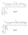
- the panel 1 may be an interference fit between adjacent joists 11, or the panel 1 may be supported on studs or laths 12 secured as by nails to the joists 11 ( Fig. 3 ) so that when the panel is inserted between the joists in the direction of the arrow 'X', the lower (as viewed) surface of the panel 1 rests on the stud 12 and the panel is supported thereby.
- a further support 13 is shown in Fig.
- a hanger suitably of metal, of Z-shape in end elevation, one limb 14 of which is supported by the joist 11 and the opposite limb 15 of which provides a support for the panel 1, as described with respect to the Fig. 3 embodiment, i.e. on insertion between the joists in the direction of arrow 'X'.
- the panels shown and described with reference to the accompanying drawings are used for heating of an upper room 5 of a building.
- the panels in use fit below the floor covering in upper floor rooms, usually at the edges of the room.
- the panels 1 provide the additional heat output necessary to give the stipulated design temperatures in the upper floor rooms and to provide temperature control, if required.
- the panels thus provide additional heating to increase the temperature achieved with convection and radiation from the heating on the ground floor to the required design temperature on the upper floors.
- a typical heating panel would be 2m x 0.5mm in plan dimensions and one or more of these panels could be fitted near to the edge of an upper floor room to make up the additional heat output required by these rooms.
- the panels only take up a relatively small proportion of the total floor area and consequently access to electrical cables (e.g. for downstairs lighting) is still possible at the centre of the room or near the walls where there are no panels. If necessary, a narrow width could be left between the heating unit and the wall to give access to any cables in the wall (e.g. power sockets).
- the width of the panel is designed as described above to fit between joists at standard centres. For example, 550mm width to fit between joists installed at 600mm centres. The length would be chosen to give the required heat output, e.g. 2m also as mentioned above.
- the body would generally be about 25mm in thickness, but any thickness which gives the necessary structural and thermal properties can be used.
- the flexible hot water pipe is of relatively small diameter, typically 10mm and is made of any suitable material such as polybutylene, PEX, PP, PE-RT of metal/plastic composite: MCP.
- the cross-over or overlap 8 described above is such as to provide acceptable bend radii when the pipe 6 is bent back through 180° to pass back through the grooves 3 in the panel 1, to provide water flow from inlet 16 to outlet 17.
- the cross-over 8 of the pipe portions are contained below the floor surface.
- this reinforcement could be a plastic moulding shaped to the end profile of the panel, including the pipe channels, which is bonded to the each end of the panel.
- panels could be constructed so that the end returns crossovers or overlaps 8 are incorporated within the length of the panels 1 i.e. entirely within the boundary or surface area of the panel rather than projecting beyond the ends as shown in Fig. 1 .
- apparatus 100, 110 for heating or cooling in the embodiment a space such as a room (or rooms) of a building comprising a panel having a body 102, 103 having a plurality of grooves 104 and a pipe for carrying a fluid supported in the grooves 102, 103, the arrangement being such that at a return part 105 of the body 102, 103 adjacent pipe portions (not shown) overlap.
- the body 102 is in the form of a panel of expanded polystyrene (EPS) which is elongate and has essentially six grooves 104 as considered from top to bottom as viewed of the panel in Fig. 5 , thereby providing five curved pipe return grooves 106, three to the right and two to the left, as viewed, the returns 106 being within the surface area of the panel 100.
- EPS expanded polystyrene
- the grooves are drawn as if opened out straight and showing varying groove depth at different intermediate points, the letters at each groove e.g. C, F in Fig. 5C matching the letter C, F in Fig. 5 .
- the grooves 104 are in the upper in use surface of the panel body 102.
- These witness lines 108 thus indicate the positions of the grooves 104, and hence pipe runs in use, so that the panel can be secured in position from below using screws or nails with large washers or heads so that such fixing means do not engage, and puncture, a pipe in use.
- Figs. 6 to 6C show a third embodiment 110 similar to that of Figs. 5 to 5C , except that in this third embodiment 110, there are four grooves 104 comprising two curved pipe return grooves 105, the inner two grooves at the left hand end of the panel being connected via a circular or omega-shaped groove 109 which does not vary in depth while at the right hand end 105 there are curved groove parts 106 connecting the first and third grooves as the second and fourth grooves respectively, to provide the overlap for the pipe runs.
- the third embodiment 110 of the panel is secured from below as in the second embodiment, and accordingly also has indicia in the form of witness lines.
- a layer of metal in the form of a self-adhesive aluminium foil is laid over the whole of the upper surface of the respective panels. There is no adhesive foil in the pipe grooves, and no overhang of aluminium by which to suspend the panels from joists.
- the panel may comprise extruded polystyrene foam (XPS) which is relatively lightweight, is denser and has a higher compressive strength than expanded polystyrene foam.
- XPS extruded polystyrene foam
- a layer of metal is then laid over the upper surface of the panel including around the inside of the grooves. The metal thus forms a liner for the grooves.
- the metal is self-adhesive aluminium foil.
- the pipes are thus in close contact with the Aluminium foil, which follows continuously the complete profile of the top (upper) surface of panel or board.
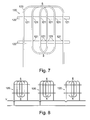
- Figs. 7 to 9 there is shown apparatus 120 in which the grooves 121 are formed in spaced support laths or struts 123, suitably of wood, and into which grooves the pipe 123, which can be a flexible plastic pipe e.g. polythene, is clipped, or engaged with a push, snap or interference fit.
- the pipe overlaps at the return 5.
- An arrangement of a plurality of apparatuses of Fig. 7 is shown in Fig. 8 , fluid such as hot water flows in at X and out at Y.
- the apparatus 120 may be in the form of a metal pipe e.g. copper secured to a panel or struts, and located in the (warm) ground 124 ( Fig.
- the apparatus 120 may be installed in a trench 125 in the ground 124, at an angle, e.g. 45°, a vertical or substantially so, the angled installation providing longer pipe lengths and optimal trench depth for maximum heat transfer to the water.
- the apparatus 120 thus provides a geothermal application.
Landscapes
- Engineering & Computer Science (AREA)
- Physics & Mathematics (AREA)
- Thermal Sciences (AREA)
- Chemical & Material Sciences (AREA)
- Combustion & Propulsion (AREA)
- Mechanical Engineering (AREA)
- General Engineering & Computer Science (AREA)
- Panels For Use In Building Construction (AREA)
- Steam Or Hot-Water Central Heating Systems (AREA)
- Floor Finish (AREA)
Applications Claiming Priority (2)
| Application Number | Priority Date | Filing Date | Title |
|---|---|---|---|
| GB0717444A GB0717444D0 (en) | 2007-09-07 | 2007-09-07 | A panel |
| GB0810320A GB0810320D0 (en) | 2008-06-05 | 2008-06-05 | Apparatus for heating and cooling |
Publications (2)
| Publication Number | Publication Date |
|---|---|
| EP2048447A2 true EP2048447A2 (fr) | 2009-04-15 |
| EP2048447A3 EP2048447A3 (fr) | 2014-04-09 |
Family
ID=40130942
Family Applications (1)
| Application Number | Title | Priority Date | Filing Date |
|---|---|---|---|
| EP08252936.3A Withdrawn EP2048447A3 (fr) | 2007-09-07 | 2008-09-04 | Panneau |
Country Status (1)
| Country | Link |
|---|---|
| EP (1) | EP2048447A3 (fr) |
Cited By (1)
| Publication number | Priority date | Publication date | Assignee | Title |
|---|---|---|---|---|
| GB2490475A (en) * | 2011-02-24 | 2012-11-07 | John David Purnell | Underfloor heating panel |
Citations (1)
| Publication number | Priority date | Publication date | Assignee | Title |
|---|---|---|---|---|
| EP0854325A2 (fr) * | 1997-01-20 | 1998-07-22 | John Lipscomb | Echangeur de chaleur |
Family Cites Families (5)
| Publication number | Priority date | Publication date | Assignee | Title |
|---|---|---|---|---|
| DE2248228C3 (de) * | 1972-10-02 | 1980-12-18 | Hans Dr.-Ing. 7410 Reutlingen Lutz | Flüssigkeitsflächenheizung für Fußböden |
| DE2551089A1 (de) * | 1975-11-14 | 1977-05-18 | Burr Martin | Fussbodenheizung |
| DE2932551C2 (de) * | 1979-08-10 | 1985-03-14 | Dietrich 6384 Schmitten Probst | Warmwasser-Flächenheizkörper, insbesondere zur Fußboden-, Wand- oder Deckenheizung |
| US5292065A (en) * | 1992-06-30 | 1994-03-08 | Joachim Fiedrich | Radiant floor and wall hydronic heating systems |
| DE20021942U1 (de) * | 2000-12-23 | 2001-03-15 | Rolltec-Heizsysteme Produktions- und Vertriebsgesellschaft mbH & Co. KG, 48282 Emsdetten | Wärmeleitende Umlenkung-Platte zum Verlegen in Flächenheizsystemen |
-
2008
- 2008-09-04 EP EP08252936.3A patent/EP2048447A3/fr not_active Withdrawn
Patent Citations (1)
| Publication number | Priority date | Publication date | Assignee | Title |
|---|---|---|---|---|
| EP0854325A2 (fr) * | 1997-01-20 | 1998-07-22 | John Lipscomb | Echangeur de chaleur |
Cited By (1)
| Publication number | Priority date | Publication date | Assignee | Title |
|---|---|---|---|---|
| GB2490475A (en) * | 2011-02-24 | 2012-11-07 | John David Purnell | Underfloor heating panel |
Also Published As
| Publication number | Publication date |
|---|---|
| EP2048447A3 (fr) | 2014-04-09 |
Similar Documents
| Publication | Publication Date | Title |
|---|---|---|
| EP2895666B1 (fr) | Ensemble de paroi hybride modulaire | |
| EP0592159B1 (fr) | Système de chauffage ou de réfrigération | |
| US20150136361A1 (en) | Heat Transfer Using Flexible Fluid Conduit | |
| US12492825B2 (en) | Plasterboard lookalike building panel radiant heater | |
| US20040026525A1 (en) | In radiant wall and ceiling hydronic room heating or cooling systems, using tubing that is fed hot or cold water, the tubing is embedded in gypsum or cement wallboard in intimate thermal contact therewith so that the wallboard heats or cools the room | |
| EP0506678A1 (fr) | Conduit a repartition d'ecoulement | |
| WO2021259896A1 (fr) | Appareil de chauffage par rayonnement à panneau de construction semblable à une plaque de plâtre | |
| EP2420749B1 (fr) | Système de climatisation pour un bâtiment | |
| RU1811573C (ru) | Излучающий сборный потолочный элемент дл системы лучистого отоплени | |
| US8145047B2 (en) | Self-regulating electric heating system | |
| EP2048447A2 (fr) | Panneau | |
| JP6926532B2 (ja) | 空調システム | |
| EP4259976B1 (fr) | Panneau de mur chauffant et élément de coin de masquage de bord de panneau de mur chauffant | |
| EP4364528A1 (fr) | Appareil de chauffage par rayonnement à panneau de construction semblable à une plaque de plâtre | |
| EP0854325A2 (fr) | Echangeur de chaleur | |
| US20240230110A1 (en) | Plasterboard lookalike building panel radiant heater | |
| JP3801593B2 (ja) | 面状発熱体と金属製床パネルを用いた二重床暖房装置 | |
| CA2905068A1 (fr) | Systeme de controle de temperature de surface | |
| US20200205236A1 (en) | Grooved Floor Underlayment for Radiant Heat | |
| EP2783767A1 (fr) | Bobine tubulaire cannelée pour le passage d'un fluide de transfert de panneaux rayonnants pour systèmes de commande de climatisation au plafond, mur ou au sol et son procédé de fourniture | |
| KR102957896B1 (ko) | 공동주택 건축물의 옥상 슬래브 단열구조 | |
| PL70945Y1 (pl) | Płyta systemowa | |
| CN212057597U (zh) | 一种模块化的室内冷暖调节和通风集成板 | |
| PL234296B1 (pl) | Panel termiczny | |
| GB2460420A (en) | Heat transfer panel with reinforcing layer |
Legal Events
| Date | Code | Title | Description |
|---|---|---|---|
| PUAI | Public reference made under article 153(3) epc to a published international application that has entered the european phase |
Free format text: ORIGINAL CODE: 0009012 |
|
| AK | Designated contracting states |
Kind code of ref document: A2 Designated state(s): AT BE BG CH CY CZ DE DK EE ES FI FR GB GR HR HU IE IS IT LI LT LU LV MC MT NL NO PL PT RO SE SI SK TR |
|
| AX | Request for extension of the european patent |
Extension state: AL BA MK RS |
|
| RAP1 | Party data changed (applicant data changed or rights of an application transferred) |
Owner name: POLYPIPE LIMITED |
|
| RIC1 | Information provided on ipc code assigned before grant |
Ipc: F24D 3/14 20060101ALN20131202BHEP Ipc: F24D 3/16 20060101AFI20131202BHEP |
|
| PUAL | Search report despatched |
Free format text: ORIGINAL CODE: 0009013 |
|
| AK | Designated contracting states |
Kind code of ref document: A3 Designated state(s): AT BE BG CH CY CZ DE DK EE ES FI FR GB GR HR HU IE IS IT LI LT LU LV MC MT NL NO PL PT RO SE SI SK TR |
|
| AX | Request for extension of the european patent |
Extension state: AL BA MK RS |
|
| RIC1 | Information provided on ipc code assigned before grant |
Ipc: F24D 3/14 20060101ALN20140306BHEP Ipc: F24D 3/16 20060101AFI20140306BHEP |
|
| 17P | Request for examination filed |
Effective date: 20141009 |
|
| RBV | Designated contracting states (corrected) |
Designated state(s): AT BE BG CH CY CZ DE DK EE ES FI FR GB GR HR HU IE IS IT LI LT LU LV MC MT NL NO PL PT RO SE SI SK TR |
|
| RBV | Designated contracting states (corrected) |
Designated state(s): AT BE BG CH CY CZ DE DK EE ES FI FR GB GR HR HU IE IS IT LI LT LU LV MC MT NL NO PL PT RO SE SI SK TR |
|
| AXX | Extension fees paid |
Extension state: AL Extension state: MK Extension state: RS Extension state: BA |
|
| RBV | Designated contracting states (corrected) |
Designated state(s): AT BE BG CH CY CZ DE DK EE ES FI FR GB GR HR HU IE IS IT LI LT LU LV MC MT NL NO PL PT RO SE SI SK TR |
|
| 17Q | First examination report despatched |
Effective date: 20150827 |
|
| STAA | Information on the status of an ep patent application or granted ep patent |
Free format text: STATUS: THE APPLICATION IS DEEMED TO BE WITHDRAWN |
|
| 18D | Application deemed to be withdrawn |
Effective date: 20160830 |