EP2048449A2 - Climatisation, en particulier pour bateaux - Google Patents
Climatisation, en particulier pour bateaux Download PDFInfo
- Publication number
- EP2048449A2 EP2048449A2 EP08017627A EP08017627A EP2048449A2 EP 2048449 A2 EP2048449 A2 EP 2048449A2 EP 08017627 A EP08017627 A EP 08017627A EP 08017627 A EP08017627 A EP 08017627A EP 2048449 A2 EP2048449 A2 EP 2048449A2
- Authority
- EP
- European Patent Office
- Prior art keywords
- air
- fan
- conditioning system
- air conditioning
- supply
- Prior art date
- Legal status (The legal status is an assumption and is not a legal conclusion. Google has not performed a legal analysis and makes no representation as to the accuracy of the status listed.)
- Withdrawn
Links
- 238000004378 air conditioning Methods 0.000 title claims description 16
- 238000000034 method Methods 0.000 claims abstract description 7
- 230000006698 induction Effects 0.000 claims description 4
- 230000001105 regulatory effect Effects 0.000 abstract description 2
- 238000001816 cooling Methods 0.000 description 3
- 238000010438 heat treatment Methods 0.000 description 3
- 230000001276 controlling effect Effects 0.000 description 2
- 238000011161 development Methods 0.000 description 2
- 230000018109 developmental process Effects 0.000 description 2
- 230000002349 favourable effect Effects 0.000 description 2
- 238000007664 blowing Methods 0.000 description 1
- 230000001143 conditioned effect Effects 0.000 description 1
- 238000007791 dehumidification Methods 0.000 description 1
- 230000001419 dependent effect Effects 0.000 description 1
- 239000000523 sample Substances 0.000 description 1
- 230000003068 static effect Effects 0.000 description 1
Images

Classifications
-
- F—MECHANICAL ENGINEERING; LIGHTING; HEATING; WEAPONS; BLASTING
- F24—HEATING; RANGES; VENTILATING
- F24F—AIR-CONDITIONING; AIR-HUMIDIFICATION; VENTILATION; USE OF AIR CURRENTS FOR SCREENING
- F24F11/00—Control or safety arrangements
- F24F11/0001—Control or safety arrangements for ventilation
-
- B—PERFORMING OPERATIONS; TRANSPORTING
- B63—SHIPS OR OTHER WATERBORNE VESSELS; RELATED EQUIPMENT
- B63J—AUXILIARIES ON VESSELS
- B63J2/00—Arrangements of ventilation, heating, cooling, or air-conditioning
- B63J2/02—Ventilation; Air-conditioning
- B63J2/04—Ventilation; Air-conditioning of living spaces
-
- F—MECHANICAL ENGINEERING; LIGHTING; HEATING; WEAPONS; BLASTING
- F24—HEATING; RANGES; VENTILATING
- F24F—AIR-CONDITIONING; AIR-HUMIDIFICATION; VENTILATION; USE OF AIR CURRENTS FOR SCREENING
- F24F1/00—Room units for air-conditioning, e.g. separate or self-contained units or units receiving primary air from a central station
- F24F1/0007—Indoor units, e.g. fan coil units
- F24F1/00075—Indoor units, e.g. fan coil units receiving air from a central station
-
- F—MECHANICAL ENGINEERING; LIGHTING; HEATING; WEAPONS; BLASTING
- F24—HEATING; RANGES; VENTILATING
- F24F—AIR-CONDITIONING; AIR-HUMIDIFICATION; VENTILATION; USE OF AIR CURRENTS FOR SCREENING
- F24F11/00—Control or safety arrangements
- F24F11/0001—Control or safety arrangements for ventilation
- F24F2011/0002—Control or safety arrangements for ventilation for admittance of outside air
- F24F2011/0004—Control or safety arrangements for ventilation for admittance of outside air to create overpressure in a room
Definitions
- the invention relates to an air conditioner according to the preamble of claim 1. Furthermore, the invention relates to a method according to the preamble of claim. 9
- a pressure difference measuring device which receives a pressure difference between the outlet and the inlet air of the room unit and measures a supply air pressure difference with respect to the duct system.
- the opening angle of the respective flap depends on the output signal of the pressure difference measuring device.
- the invention has for its object to improve an air conditioner of the type mentioned so that line losses are reduced, with a remedy against an uncomfortable perceived noise is possible.
- the invention enables virtually active volumetric flow control, which therefore no longer requires passive volumetric flow controllers over solutions with adjusting flaps.
- each supply air unit is provided with a differential pressure sensor, which is connected to a controller comprising an electrical control element for controlling a fan motor of the fan.
- a controller comprising an electrical control element for controlling a fan motor of the fan.
- controller is equipped with an external setpoint input.
- a pressure change with regard to a supply request for example a desired setpoint temperature or setpoint differential pressure
- An external actuator connected to the setpoint input such as a rotary potentiometer, Tap-changer or the like with control knob, can then be connected to the setpoint input, so that from the respective cabin from an individual temperature or flow setting is adjustable.
- a remote control using a Fembedienilless or other solutions are also possible.
- each supply air unit comprises an air rectifier. This can prevent air from being sucked out of the cabin and conveyed back into the main duct when, for example, other fans of other cabs are operated at a relatively high speed. Such an arrangement is particularly favorable when using axial fans.
- an axial fan is favorable if a high volume flow is to be possible. This is advantageous, for example, in large cabins.
- an axial fan is very quiet.
- a radial fan is better if a large pressure difference would be overcome. So quite different types of fans along the main channel can be used.
- an air supply device is used, which is designed as an induction device.
- the air supply device comprises a lower air outlet, an electric air heater and / or a cooler and a top-mounted primary air connection with a fan. It can be accomplished optimally heating and / or cooling of the cabins.
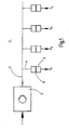
- Fig. 1 shows an air conditioner 1 of a ship. This is used for the air treatment of cabins but basically also other ship rooms. For the sake of simplicity, however, cabins are used.
- the air conditioning system 1 comprises a central air supply device 2. This consists of a central air conditioner for cooling and / or heating the individual ship cabins.
- the air supply device 2 also comprises a central fan for conveying air in a main channel 3, which is connected to this device 2.
- the main channel 3 has a relatively large length of, for example, at least over 100 meters or even a multiple thereof.
- a ship may for example be a cruise ship with a significant number of ship cabins, in particular at least 200 cabins or significantly more.
- the main channel 3 along the entire length preferably always has the same cross section.
- the main channel 3 is provided with a plurality of branch channels 4 for air conditioning in the various cabins.
- Each branch channel 4 is provided with a supply air unit 5, wherein an air outlet to the corresponding cabin is present.
- each supply air unit 5 is provided with a fan 6, which conveys a volume flow into the cabin.
- Each fan 6 is powered by the electrical system of the ship.
- each fan 6 generates just that much differential pressure, that an air flow in the room is promoted with little or no pressure.
- the arrows in Fig. 1 indicate only the volume flows V 1 to V 4 of the cabins, but with a significantly higher number of branches are present.
- each supply air unit 5 has an intake port 7 connected to the respective branch passage 4 and an exhaust port 8 leading to the car.
- each supply air unit 5 is provided with a measuring probe, in particular a differential pressure sensor 10. This is connected to an electric control element comprehensive regulator 11 for controlling a fan motor 12 of the fan 5.
- a control element for controlling each control element is suitable, which compensates for dynamic pressure fluctuations. To control pressure fluctuations, a fixed differential pressure setpoint can be taken into account.
- the controller 11 may be provided with an external setpoint input 13. This input can be used to set a desired temperature or another supply request.
- an individual pressure difference ⁇ p can be set for the respective cabin. For example, if a high volume flow of cold air to be promoted, then a higher pressure difference is to be specified, as if only a small volume flow of cold air to flow into the cabin.
- the fans 5 used are fans of relatively low power or smaller dimensions. They have a much smaller performance compared to the central fan. Such a fan rated power can be for example 1 to 10W.
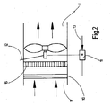
- Fig. 2 In the air flow control according to Fig. 2 is used as fan 5, an axial fan.
- the sensor 10 is located in the flow path in front of the fan 5, wherein between the sensor and the fan 5, an air rectifier 15 is installed so that air can flow only in the same direction.
- the supply air unit 5 according to Fig. 3 a radial fan in which air is sucked laterally and conveyed through the fan outlet opening 14.
- the sensor 10 is arranged behind the fan 5.
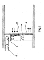
- the Fig. 4 shows the air supply device in a cabin, which consists of a fan 17 connected to a primary air connection 16 of the central air conditioner.
- This air supply device is designed as an induction device.
- the air outlet 18 of the device below is the air outlet 18 of the device, while the primary air connection 16 is at the top. Above the air outlet 18 is an electric air heater 19 for heating the cabin. In addition, a cooler 20 is provided, which serves for cooling and dehumidification.
- a central air flow is practically divided into several branch streams conducted to the cabins. There is a pressure reduction at each branch flow through the corresponding fan 5, in such a way that a differential pressure is built up and an air flow is conveyed into the cabin with little or no overpressure.
- the invention is not limited to this example.
- a skyscraper or the like can be conditioned by the system 1 according to the invention.
- the supply line in the branch channel 4 can also belong to the supply air unit 5, so that the fans 6 can also be arranged in the region of the supply line.
Landscapes
- Engineering & Computer Science (AREA)
- Chemical & Material Sciences (AREA)
- Combustion & Propulsion (AREA)
- Mechanical Engineering (AREA)
- General Engineering & Computer Science (AREA)
- Ocean & Marine Engineering (AREA)
- Air Conditioning Control Device (AREA)
- Air-Conditioning For Vehicles (AREA)
- Soundproofing, Sound Blocking, And Sound Damping (AREA)
Applications Claiming Priority (1)
| Application Number | Priority Date | Filing Date | Title |
|---|---|---|---|
| DE102007049333A DE102007049333B4 (de) | 2007-10-12 | 2007-10-12 | Klimaanlage, insbesondere für Schiffe |
Publications (2)
| Publication Number | Publication Date |
|---|---|
| EP2048449A2 true EP2048449A2 (fr) | 2009-04-15 |
| EP2048449A3 EP2048449A3 (fr) | 2009-08-19 |
Family
ID=40052561
Family Applications (1)
| Application Number | Title | Priority Date | Filing Date |
|---|---|---|---|
| EP08017627A Withdrawn EP2048449A3 (fr) | 2007-10-12 | 2008-10-08 | Climatisation, en particulier pour bateaux |
Country Status (2)
| Country | Link |
|---|---|
| EP (1) | EP2048449A3 (fr) |
| DE (1) | DE102007049333B4 (fr) |
Cited By (8)
| Publication number | Priority date | Publication date | Assignee | Title |
|---|---|---|---|---|
| CN103912957A (zh) * | 2014-03-25 | 2014-07-09 | 珠海格力电器股份有限公司 | 空调机组的控制方法、控制装置及空调机组 |
| JP2014201271A (ja) * | 2013-04-09 | 2014-10-27 | ヤンマー株式会社 | 船舶用空調装置 |
| CN106196431A (zh) * | 2016-07-04 | 2016-12-07 | 珠海格力电器股份有限公司 | 空调风管机控制系统、方法和装置 |
| EP3385159A1 (fr) | 2017-04-07 | 2018-10-10 | EMCO Klima GmbH | Appareil, system et méthode de climatisation de cabine de navire |
| DE102017107582A1 (de) | 2017-04-07 | 2018-10-11 | Emco Klima Gmbh | Klimatisierung von Schiffskabinen |
| DE102017125758A1 (de) | 2017-11-03 | 2019-05-09 | Emco Klima Gmbh | Dezentrale Klimatisierung von Schiffskabinen |
| CN113148096A (zh) * | 2021-04-23 | 2021-07-23 | 沪东中华造船(集团)有限公司 | 一种船舶空调送风系统及送风方法 |
| CN114063665A (zh) * | 2021-11-23 | 2022-02-18 | 合肥杜威智能科技股份有限公司 | 一种密闭船舱室内压差控制装置 |
Families Citing this family (3)
| Publication number | Priority date | Publication date | Assignee | Title |
|---|---|---|---|---|
| DE102011053300A1 (de) * | 2011-09-06 | 2013-03-07 | Schako Klima Luft, Ferdinand Schad Kg | Verfahren zum Regeln der Belüftung von Räumen |
| DE102012220391A1 (de) * | 2012-11-08 | 2014-05-08 | Fraunhofer-Gesellschaft zur Förderung der angewandten Forschung e.V. | System zur Belüftung eines Gebäudes |
| DE102013214158A1 (de) * | 2013-07-18 | 2015-01-22 | Fraunhofer-Gesellschaft zur Förderung der angewandten Forschung e.V. | Belüftungssystem für ein Gebäude |
Citations (1)
| Publication number | Priority date | Publication date | Assignee | Title |
|---|---|---|---|---|
| DE4031113A1 (de) | 1989-12-07 | 1991-06-13 | Mitsubishi Electric Corp | Klimaanlage |
Family Cites Families (12)
| Publication number | Priority date | Publication date | Assignee | Title |
|---|---|---|---|---|
| DE4223031C2 (de) * | 1992-07-14 | 1995-11-23 | Schmidt Christel | Vorrichtung zur Kühlung von Räumen |
| FR2702547B1 (fr) * | 1993-03-11 | 1995-05-12 | Jacques Signoret | Procédé et installation pour le conditionnement et la pressurisation d'un espace semi-clos. |
| DE19654955C2 (de) * | 1996-12-27 | 2000-11-16 | Albert Bauer | Klimatisierungsvorrichtung |
| SE514252C2 (sv) * | 1998-05-14 | 2001-01-29 | Abb Ab | Ventilation |
| DE29922899U1 (de) * | 1999-12-30 | 2000-03-02 | Sehon, Tiemo, 75391 Gechingen | Vorrichtung zum Regeln des Druckes in einem Arbeitsraum, insbesondere in Lackierkabinen |
| FR2805601B1 (fr) * | 2000-02-29 | 2002-06-07 | Aldes Aeraulique | Groupe de ventilation auto-pilote a regulation electronique |
| DE10121286A1 (de) * | 2001-04-30 | 2002-10-31 | Valeo Klimasysteme Gmbh | Luftführungsgehäuse |
| ATE382837T1 (de) * | 2003-03-04 | 2008-01-15 | Imtech Deutschland Gmbh & Co K | Raumtemperierungseinrichtung |
| ITBO20040280A1 (it) * | 2004-05-04 | 2004-08-04 | Busi Impianti Spa | Apparecchiatura di controllo ambientale dinamico e relalativo impianto a portata d'aria variabile. |
| DE202004016229U1 (de) * | 2004-10-19 | 2005-01-05 | Leithner, Hans Joachim | Vorrichtung zum Erzeugen eines Luftüberdruckes in einem Flucht-Treppenhaus |
| DE102005057454B4 (de) * | 2005-12-01 | 2007-09-13 | Black Box Gmbh & Co.Kg | Luftdichtevergleichsregelung |
| GB0526155D0 (en) * | 2005-12-22 | 2006-02-01 | Lowther Peter Q | A fan coil air conditionig system and plenum chamber therefor |
-
2007
- 2007-10-12 DE DE102007049333A patent/DE102007049333B4/de active Active
-
2008
- 2008-10-08 EP EP08017627A patent/EP2048449A3/fr not_active Withdrawn
Patent Citations (1)
| Publication number | Priority date | Publication date | Assignee | Title |
|---|---|---|---|---|
| DE4031113A1 (de) | 1989-12-07 | 1991-06-13 | Mitsubishi Electric Corp | Klimaanlage |
Cited By (9)
| Publication number | Priority date | Publication date | Assignee | Title |
|---|---|---|---|---|
| JP2014201271A (ja) * | 2013-04-09 | 2014-10-27 | ヤンマー株式会社 | 船舶用空調装置 |
| CN103912957A (zh) * | 2014-03-25 | 2014-07-09 | 珠海格力电器股份有限公司 | 空调机组的控制方法、控制装置及空调机组 |
| CN106196431A (zh) * | 2016-07-04 | 2016-12-07 | 珠海格力电器股份有限公司 | 空调风管机控制系统、方法和装置 |
| EP3385159A1 (fr) | 2017-04-07 | 2018-10-10 | EMCO Klima GmbH | Appareil, system et méthode de climatisation de cabine de navire |
| DE102017107582A1 (de) | 2017-04-07 | 2018-10-11 | Emco Klima Gmbh | Klimatisierung von Schiffskabinen |
| DE102017125758A1 (de) | 2017-11-03 | 2019-05-09 | Emco Klima Gmbh | Dezentrale Klimatisierung von Schiffskabinen |
| CN113148096A (zh) * | 2021-04-23 | 2021-07-23 | 沪东中华造船(集团)有限公司 | 一种船舶空调送风系统及送风方法 |
| CN114063665A (zh) * | 2021-11-23 | 2022-02-18 | 合肥杜威智能科技股份有限公司 | 一种密闭船舱室内压差控制装置 |
| CN114063665B (zh) * | 2021-11-23 | 2024-02-09 | 合肥杜威智能科技股份有限公司 | 一种密闭船舱室内压差控制装置 |
Also Published As
| Publication number | Publication date |
|---|---|
| DE102007049333A1 (de) | 2009-04-23 |
| DE102007049333B4 (de) | 2009-10-15 |
| EP2048449A3 (fr) | 2009-08-19 |
Similar Documents
| Publication | Publication Date | Title |
|---|---|---|
| DE102007049333B4 (de) | Klimaanlage, insbesondere für Schiffe | |
| DE102008057787B3 (de) | Regelvorrichtung für raumlufttechnische Anlagen | |
| EP3172104B1 (fr) | Dispositif de distribution d'air pour l'espace intérieur d'un véhicule ferroviaire | |
| EP3156302B1 (fr) | Dispositif de climatisation d'un habitacle d'un véhicule ferroviaire | |
| DE2953168A1 (en) | Air distribution system | |
| EP0802076A2 (fr) | Méthode d'opération d'un appareil de chauffage ou de climatisation | |
| EP2275687A2 (fr) | Boîtier de ventilateur radial | |
| DE60221007T2 (de) | Heizungs-, belüftungs- und/oder klimaanlagen | |
| EP1571402B1 (fr) | Appareil de traitement de l'air d'une pièce pour chauffer, refroidir et/ou ventiler une pièce et méthode correspondante | |
| EP2250444B1 (fr) | Système de climatisation à deux canaux, pour la climatisation flexible d un certain nombre de locaux | |
| EP1191287A2 (fr) | Système de tuyauterie pour l'échange d'énergie thermique | |
| DE102014209452A1 (de) | Klimaanlage mit Bypassvorrichtung | |
| EP2846106B1 (fr) | Dispositif d'aération de pièce et méthode de réglage de débit d'air pour un dispositif d'aération de pièce | |
| EP0037843A1 (fr) | Dispositif de climatisation pour une multitude de locaux, spécialement pour des cabines de bateau | |
| EP3065993B1 (fr) | Procédé de climatisation d'un véhicule, en particulier d'un véhicule ferroviaire | |
| EP3809054B1 (fr) | Installation technique d'air ambiant et / ou de climatisation destinée à l'aération d'une pièce ou des pièces dotée d'au moins une conduite d'air principale et procédé de réglage d'une installation technique d'air ambiant et / ou de climatisation destinée à l'aération d'une pièce ou des pièces dotée d'au moins une conduite d'air principale | |
| DE2928134A1 (de) | Einrichtung zur temperaturregelung im fahrgastraum von landfahrzeugen, insbesondere von omnibussen | |
| DE2807901C3 (de) | Steuervorrichtung zur Steuerung eines Zuluftstromes und eines Abluftstromes | |
| DE3114528A1 (de) | Luftverteilgeraet zur temperierung | |
| EP1571019B1 (fr) | Dispositif de conditionnement d'air, notamment pour véhicule automobile | |
| EP3480529A1 (fr) | Procédé de climatisation des unités d'espace d'un bâtiment | |
| DE590446C (de) | Verfahren und Vorrichtungen zur Regelung der Belueftung bzw. Erwaermung von Raeumen jeder Art | |
| EP1429081B9 (fr) | Système de ventilation pour la ventilation d'un local | |
| DE102023113881A1 (de) | Klimagerät für ein Kraftfahrzeug sowie Klimatisierungssystem mit dem Klimagerät und Verfahren zum Betreiben des Klimagerätes | |
| EP1694521B1 (fr) | Unite de ventilation pour vehicules a moteur |
Legal Events
| Date | Code | Title | Description |
|---|---|---|---|
| PUAI | Public reference made under article 153(3) epc to a published international application that has entered the european phase |
Free format text: ORIGINAL CODE: 0009012 |
|
| AK | Designated contracting states |
Kind code of ref document: A2 Designated state(s): AT BE BG CH CY CZ DE DK EE ES FI FR GB GR HR HU IE IS IT LI LT LU LV MC MT NL NO PL PT RO SE SI SK TR |
|
| AX | Request for extension of the european patent |
Extension state: AL BA MK RS |
|
| PUAL | Search report despatched |
Free format text: ORIGINAL CODE: 0009013 |
|
| AK | Designated contracting states |
Kind code of ref document: A3 Designated state(s): AT BE BG CH CY CZ DE DK EE ES FI FR GB GR HR HU IE IS IT LI LT LU LV MC MT NL NO PL PT RO SE SI SK TR |
|
| AX | Request for extension of the european patent |
Extension state: AL BA MK RS |
|
| AKX | Designation fees paid | ||
| STAA | Information on the status of an ep patent application or granted ep patent |
Free format text: STATUS: THE APPLICATION IS DEEMED TO BE WITHDRAWN |
|
| 18D | Application deemed to be withdrawn |
Effective date: 20100220 |
|
| REG | Reference to a national code |
Ref country code: DE Ref legal event code: 8566 |