EP2048464A2 - Bearbeitungseinheit für körniges Material mit einer Regenerationswärme-Einheit - Google Patents
Bearbeitungseinheit für körniges Material mit einer Regenerationswärme-Einheit Download PDFInfo
- Publication number
- EP2048464A2 EP2048464A2 EP08166115A EP08166115A EP2048464A2 EP 2048464 A2 EP2048464 A2 EP 2048464A2 EP 08166115 A EP08166115 A EP 08166115A EP 08166115 A EP08166115 A EP 08166115A EP 2048464 A2 EP2048464 A2 EP 2048464A2
- Authority
- EP
- European Patent Office
- Prior art keywords
- treatment unit
- heat
- granular material
- unit according
- gas medium
- Prior art date
- Legal status (The legal status is an assumption and is not a legal conclusion. Google has not performed a legal analysis and makes no representation as to the accuracy of the status listed.)
- Withdrawn
Links
Images



Classifications
-
- F—MECHANICAL ENGINEERING; LIGHTING; HEATING; WEAPONS; BLASTING
- F26—DRYING
- F26B—DRYING SOLID MATERIALS OR OBJECTS BY REMOVING LIQUID THEREFROM
- F26B23/00—Heating arrangements
- F26B23/001—Heating arrangements using waste heat
- F26B23/002—Heating arrangements using waste heat recovered from dryer exhaust gases
-
- B—PERFORMING OPERATIONS; TRANSPORTING
- B29—WORKING OF PLASTICS; WORKING OF SUBSTANCES IN A PLASTIC STATE IN GENERAL
- B29B—PREPARATION OR PRETREATMENT OF THE MATERIAL TO BE SHAPED; MAKING GRANULES OR PREFORMS; RECOVERY OF PLASTICS OR OTHER CONSTITUENTS OF WASTE MATERIAL CONTAINING PLASTICS
- B29B15/00—Pretreatment of the material to be shaped, not covered by groups B29B7/00 - B29B13/00
-
- B—PERFORMING OPERATIONS; TRANSPORTING
- B29—WORKING OF PLASTICS; WORKING OF SUBSTANCES IN A PLASTIC STATE IN GENERAL
- B29B—PREPARATION OR PRETREATMENT OF THE MATERIAL TO BE SHAPED; MAKING GRANULES OR PREFORMS; RECOVERY OF PLASTICS OR OTHER CONSTITUENTS OF WASTE MATERIAL CONTAINING PLASTICS
- B29B13/00—Conditioning or physical treatment of the material to be shaped
- B29B13/06—Conditioning or physical treatment of the material to be shaped by drying
- B29B13/065—Conditioning or physical treatment of the material to be shaped by drying of powder or pellets
-
- B—PERFORMING OPERATIONS; TRANSPORTING
- B29—WORKING OF PLASTICS; WORKING OF SUBSTANCES IN A PLASTIC STATE IN GENERAL
- B29B—PREPARATION OR PRETREATMENT OF THE MATERIAL TO BE SHAPED; MAKING GRANULES OR PREFORMS; RECOVERY OF PLASTICS OR OTHER CONSTITUENTS OF WASTE MATERIAL CONTAINING PLASTICS
- B29B9/00—Making granules
- B29B9/16—Auxiliary treatment of granules
-
- F—MECHANICAL ENGINEERING; LIGHTING; HEATING; WEAPONS; BLASTING
- F26—DRYING
- F26B—DRYING SOLID MATERIALS OR OBJECTS BY REMOVING LIQUID THEREFROM
- F26B17/00—Machines or apparatus for drying materials in loose, plastic, or fluidised form, e.g. granules, staple fibres, with progressive movement
- F26B17/12—Machines or apparatus for drying materials in loose, plastic, or fluidised form, e.g. granules, staple fibres, with progressive movement with movement performed solely by gravity, i.e. the material moving through a substantially vertical drying enclosure, e.g. shaft
- F26B17/14—Machines or apparatus for drying materials in loose, plastic, or fluidised form, e.g. granules, staple fibres, with progressive movement with movement performed solely by gravity, i.e. the material moving through a substantially vertical drying enclosure, e.g. shaft the materials moving through a counter-current of gas
- F26B17/1408—Machines or apparatus for drying materials in loose, plastic, or fluidised form, e.g. granules, staple fibres, with progressive movement with movement performed solely by gravity, i.e. the material moving through a substantially vertical drying enclosure, e.g. shaft the materials moving through a counter-current of gas the gas being supplied and optionally extracted through ducts extending into the moving stack of material
- F26B17/1425—Machines or apparatus for drying materials in loose, plastic, or fluidised form, e.g. granules, staple fibres, with progressive movement with movement performed solely by gravity, i.e. the material moving through a substantially vertical drying enclosure, e.g. shaft the materials moving through a counter-current of gas the gas being supplied and optionally extracted through ducts extending into the moving stack of material the ducts being perforated and arranged vertically
-
- F—MECHANICAL ENGINEERING; LIGHTING; HEATING; WEAPONS; BLASTING
- F26—DRYING
- F26B—DRYING SOLID MATERIALS OR OBJECTS BY REMOVING LIQUID THEREFROM
- F26B21/00—Arrangements for supplying or controlling air or other gases for drying solid materials or objects
- F26B21/20—Circulating air or gases in closed cycles, e.g. wholly within the drying enclosure
- F26B21/25—Circulating air or gases in closed cycles, e.g. wholly within the drying enclosure partly outside the drying enclosure
-
- Y—GENERAL TAGGING OF NEW TECHNOLOGICAL DEVELOPMENTS; GENERAL TAGGING OF CROSS-SECTIONAL TECHNOLOGIES SPANNING OVER SEVERAL SECTIONS OF THE IPC; TECHNICAL SUBJECTS COVERED BY FORMER USPC CROSS-REFERENCE ART COLLECTIONS [XRACs] AND DIGESTS
- Y02—TECHNOLOGIES OR APPLICATIONS FOR MITIGATION OR ADAPTATION AGAINST CLIMATE CHANGE
- Y02P—CLIMATE CHANGE MITIGATION TECHNOLOGIES IN THE PRODUCTION OR PROCESSING OF GOODS
- Y02P70/00—Climate change mitigation technologies in the production process for final industrial or consumer products
- Y02P70/10—Greenhouse gas [GHG] capture, material saving, heat recovery or other energy efficient measures, e.g. motor control, characterised by manufacturing processes, e.g. for rolling metal or metal working
Definitions
- the present invention relates to a treatment unit for granular material having a heat-regeneration group.
- the term "granular” means both materials that are classified as such by being naturally made of granules and those obtained by a milling process (such as those known as re-milled products) and powders.
- a granular material is loaded into and kept in silos, also called “hoppers”, for a predetermined time.
- a hot and dehumidified gas medium such as dry hot air or inert gas, typically nitrogen, is caused to flow through them.
- the gas medium After flowing through the granular material in a silo, the gas medium is collected and recycled after having been filtered and heated/dehumidified in order giving it features of humidity, temperature, etc. required for that specific granular material to be treated.
- Granular material dehumidifying plants have already been proposed where, the employed gas medium leaving a dehumidification silo or hopper is conveyed trough a suitable duct to a remote, i.e. relatively far from the silo, heat exchanger for recovering its residual heat, and thus for being cooled.
- the treatment gas medium air
- the gas medium is supplied to a lower area of the silo so that the gas medium is caused to flow throughout the entire useful height of the silo, and thus to hit practically all the material in it, so as to perform forced dehumidification and preheating of the granular material that will, consequently, be used in optimum conditions for subsequent processing.
- the processing air at the outlet of a treatment hopper is charged with humidity and still possesses a considerable amount of heat that is usually employed to pre-heat the processing air to be supplied to the hopper through dehumidification equipments.
- cooling of the air coming out form the hopper is also obtained, and in view of the fact that the air flow coming out from the hopper, as known, has to be conveyed first to a pressurization unit (such as a blower) and then to a water adsorbing unit, this is advantageous for optimum working of both such units.
- a plant of this type involves considerable heat dispersion, which takes place at least in the connecting ducts between hopper and heat-exchanging group and cannot be reduced below certain limits even by providing good insulating materials around the connecting ducts.
- such a plant requires a very large plant volume and suitable support structures for both the silo or hopper and the heat-exchanging group.
- the first aim of the present invention is to provide a treatment unit for granular materials and particularly plastic granular materials, that is suitable for eliminating or drastically reducing the drawbacks mentioned above in connection with the conventional granular materials treatment plants.
- Another object of the present invention is to provide a granular material' treatment unit which can operate in optimum conditions for both the dehumidification processing of granular material and the heat regeneration from the gas medium used for processing the granular material.
- Another object of the present invention is to provide a compact treatment unit obtainable at competitive manufacturing costs.
- Still another object of the resent invention is to provide a dehumidification and/or drying plant designed for correctly perform treatment operations on granular materials at a lower energy consumption than with conventional plants.
- a treatment unit for a granular material comprising:
- the treatment unit further comprises:
- a dehumidification plant for granular material comprising:
- a treatment unit 1 for granular materials such as granular plastic materials
- a support structure S which delimits a receiving cavity 3 for at least one granular material which is supplied through a loading mouth 4 and exits through a granular material discharging or delivery mouth 5, the latter being located in a lower area of the silo 2.
- Feeding means of at least one treatment gas medium e. g. air or an inert gas, such as nitrogen, are also provided internally and specifically at a heat-exchanging group.
- An outlet or a plurality of outlets for the gas medium is provided at the top of the treatment unit.
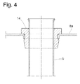
- the feeding means comprise a feeding pipe or duct 6, e. g. an ell member, which from the top of the silo extends downwards to a lower zone of the silo where it is in fluid communication with a dispenser 6a of treatment gas medium.
- the treatment unit further comprises a heat exchanging group 8 which can be secured at the top of cavity 3 and arranged to partly close it.
- the heat exchanging group 8 comprises:
- the plurality of ducts and chamber 10 are thus arranged in heat exchange relationship.
- ducts 9 are arranged to deliver a treatment gas medium therein from cavity 3 to a manifold area 11 provided between the heat-exchanging group 8 and a top roof plate 12, which is in fluid communication with the outside through a duct 12a having an annular cross section.
- the heat-exchanging group 8 preferably comprises two substantially identical walls or plate elements, i. e. a base wall 8a and a top wall 8b, respectively, which have a ring configuration and are connected to one another through an outer side wall or jacket 8c, possibly wound by a layer of a heat insulating or lagging material 8d.
- Each ring wall delimits a central circular opening into which a granular material feeding duct 13 of can be inserted that extends to loading mouth 4.
- a plurality of bores F are provided in the plate elements 8a, 8b so that each bore on a plate element 8a, 8b is substantially in line with a bore on the other plate element 8b, 8a, respectively, and thus each duct 9 is fitted into two aligned bores each formed in a respective plate element 8a, 8b.
- annular joint sealing elements 14 e. g. made of a thermoplastic material such as Santoprene® (registered trademark of Advanced Elastomer Systems, L.P.) along the edge of each bore before assembling any duct 9.
- Santoprene® registered trademark of Advanced Elastomer Systems, L.P.
- the inlet opening 10a and the outlet opening 10b for gas medium are provided, instead, by inserting and securing, e. g. through welding, a respective sleeve collar into bores formed in the jacket or side wall 8c.
- a filtering group 15 for the gas medium is located, in use, immediately below the heat exchanging group and can be secured either to silo 2 or to the plate element or base wall 8b.
- silo 2 can comprise, in use, a lower portion having a configuration of a truncated cone 2a, and an intermediate substantially cylindrical portion 2b (located at the same level as the dispenser 6a). Moreover, a layer of heat-insulating or lagging material 2c can be provided on silo 2.
- the treatment unit according to the present invention can be employed in a plant for processing granular materials, such as granular plastic materials, as illustrated in Fig. 5 .
- Such a plant comprises a treatment unit 1 for granular materials, a filter 16 designed to receive the air that comes out of the top of the treatment unit 1 and is then conveyed to a dryer 17, where it is dehumidified and then supplied to chamber 10 for being pre-heated.
- the pre-heated air is first supplied to a heater or heating means 18 and then to the feeding means 6 for being again fed to the receiving cavity 3 for heating and dehumidifying the granular material contained therein.
- compression means e. g. a blower
- a blower can be employed, while possibly supplying the gas medium at a relatively high pressure to the plant, monitoring the pressure thereof during the processing steps and, if necessary, energizing the pressurizing means when the pressure becomes lower than a predetermined level.
- the still hot air leaving the receiving cavity is loaded with humidity that was absorbed while flowing through the granular material, releases a good deal of its enthalpy while pre-heating the processing fluid coming from the dryer 17.
- the required power required for heating the processing gas medium, i.e. the air to be fed to the hopper, by means of an electrical resistance or heater 18 in order to heat it to a predetermined temperature suitable for processing a granular material will then be certainly lower than that required with the solutions proposed up to now.
- the air discharged from the hopper has already been partly cooled down due to heat exchanged with the processing gas medium (air to be conveyed to the hopper), and thus another heat-exchanger could be no longer necessary for the cooling thereof, and the air can then be again conveyed to the dryer, possibly after flowing through filter 16.
- ducts having a large cross-section and thus do not clog easily and do not require a thorough air filtration are provided, and thus low powered filtering means can be adopted.
- the treatment unit is not affected by the negative effects caused by thermal expansion mainly in the axial direction of each duct, whereas in conventional heat-exchangers where tubes are welded, welding resistance could be drastically impaired when temperatures of fluids to be heated/cooled change on a large scale.
- the air temperature coming from the treatment unit is lower than that of the air coming from hoppers in conventional treatment plants, and this results in an improvement of security for operators inspecting the plant, particularly in the upper part of the hopper.
- hoppers or silos having a squared o polygonal cross-section can be employed.
Landscapes
- Engineering & Computer Science (AREA)
- Mechanical Engineering (AREA)
- General Engineering & Computer Science (AREA)
- Life Sciences & Earth Sciences (AREA)
- Sustainable Development (AREA)
- Drying Of Solid Materials (AREA)
- Processing And Handling Of Plastics And Other Materials For Molding In General (AREA)
- Superconductors And Manufacturing Methods Therefor (AREA)
- Processing Of Solid Wastes (AREA)
- Fertilizers (AREA)
Applications Claiming Priority (1)
| Application Number | Priority Date | Filing Date | Title |
|---|---|---|---|
| IT000140A ITVR20070140A1 (it) | 2007-10-09 | 2007-10-09 | Unita' di trattamento di materiali granulari dotata di gruppo di recupero calore |
Publications (1)
| Publication Number | Publication Date |
|---|---|
| EP2048464A2 true EP2048464A2 (de) | 2009-04-15 |
Family
ID=40202938
Family Applications (1)
| Application Number | Title | Priority Date | Filing Date |
|---|---|---|---|
| EP08166115A Withdrawn EP2048464A2 (de) | 2007-10-09 | 2008-10-08 | Bearbeitungseinheit für körniges Material mit einer Regenerationswärme-Einheit |
Country Status (5)
| Country | Link |
|---|---|
| US (1) | US20090090019A1 (de) |
| EP (1) | EP2048464A2 (de) |
| KR (1) | KR20090036536A (de) |
| CN (1) | CN101408368A (de) |
| IT (1) | ITVR20070140A1 (de) |
Cited By (1)
| Publication number | Priority date | Publication date | Assignee | Title |
|---|---|---|---|---|
| WO2019106446A1 (en) * | 2017-11-29 | 2019-06-06 | Nol-Tec Europe S.R.L. | Device and method for degassing granular or powder material and the use of a blower element for degassing said material |
Families Citing this family (9)
| Publication number | Priority date | Publication date | Assignee | Title |
|---|---|---|---|---|
| AT9203U1 (de) * | 2006-04-06 | 2007-06-15 | Econ Maschb Und Steuerungstech | Trocknungseinrichtung |
| RU2425303C1 (ru) * | 2010-01-11 | 2011-07-27 | Государственное научное учреждение Всероссийский научно-исследовательский институт механизации сельского хозяйства (ГНУ ВИМ Россельхозакадемии) | Способ сушки семян и зерна |
| USD671563S1 (en) * | 2011-04-20 | 2012-11-27 | Moretto S.P.A. | Hopper |
| USD671564S1 (en) * | 2011-04-20 | 2012-11-27 | Moretto S.P.A. | Hopper |
| US20150159948A1 (en) * | 2013-12-06 | 2015-06-11 | Darren Larson | Method and apparatus for curing canola |
| IT201900005320A1 (it) * | 2019-04-08 | 2020-10-08 | Piovan Spa | Tramoggia per condizionare termicamente materie plastiche, impianto includente tale tramoggia e metodo utilizzante tale tramoggia |
| IT202000007147A1 (it) * | 2020-04-03 | 2021-10-03 | Piovan Spa | Apparato e Metodo di Trattamento di Materiale Incoerente |
| EP3978853A1 (de) * | 2020-10-02 | 2022-04-06 | Labotek A/S | Vertikales trocknersilo |
| IT202200011555A1 (it) * | 2022-05-31 | 2023-12-01 | Piovan Spa | Apparato e metodo per processare materiale in una tramoggia |
Family Cites Families (13)
| Publication number | Priority date | Publication date | Assignee | Title |
|---|---|---|---|---|
| US447155A (en) * | 1891-02-24 | Fifth to amable b | ||
| US2579607A (en) * | 1948-03-10 | 1951-12-25 | Leo J O'shaughnessy | Continuous drier |
| US3859735A (en) * | 1974-01-23 | 1975-01-14 | Jr Herman E Katterjohn | Dryer preheater |
| US4468868A (en) * | 1982-06-30 | 1984-09-04 | Owens-Corning Fiberglas Corporation | Gas-solid counterflow vessel |
| US4676007A (en) * | 1985-02-14 | 1987-06-30 | Good Harold M | Heat exchanger for grain elevators or bins |
| EP0669510B1 (de) * | 1994-02-25 | 1998-12-02 | Motan Holding GmbH | Trockner |
| FR2744205B1 (fr) * | 1996-01-26 | 1998-04-17 | Anjou Piscine Service | Echangeur de chaleur et machine pour le montage d'un tel echangeur |
| DE19902327A1 (de) * | 1999-01-21 | 2000-07-27 | Mann & Hummel Protec Gmbh | Verfahren zum Aufheizen von Schüttgütern, insbesondere Kunststoffgranulat |
| DE10028590B4 (de) * | 2000-06-14 | 2013-08-01 | Motan Holding Gmbh | Trocknungseinrichtung zur Trocknung von Schüttgütern |
| ITPD20040258A1 (it) * | 2004-10-18 | 2005-01-18 | Moretto P A Srl | Tramoggia per la deumidificazione di materiale particolato sfuso |
| ITVR20040162A1 (it) * | 2004-10-19 | 2005-01-19 | Moretto Plastics Automation Srl | Deumidificatore ad adsorbimento per granuli di materiale plastico |
| ITVR20060030A1 (it) * | 2006-02-10 | 2007-08-11 | Moretto Spa | Impianto e procedimento di deumidificazione a funzionamento flessibile particolarmente per materiali granulari. |
| ITVR20070074A1 (it) * | 2007-05-25 | 2008-11-26 | Moretto Spa | Impianto e procedimento di deumidificazione a portata variabile per materiali granulari |
-
2007
- 2007-10-09 IT IT000140A patent/ITVR20070140A1/it unknown
-
2008
- 2008-10-07 US US12/246,883 patent/US20090090019A1/en not_active Abandoned
- 2008-10-08 EP EP08166115A patent/EP2048464A2/de not_active Withdrawn
- 2008-10-09 KR KR1020080099310A patent/KR20090036536A/ko not_active Withdrawn
- 2008-10-09 CN CNA2008101702082A patent/CN101408368A/zh active Pending
Cited By (2)
| Publication number | Priority date | Publication date | Assignee | Title |
|---|---|---|---|---|
| WO2019106446A1 (en) * | 2017-11-29 | 2019-06-06 | Nol-Tec Europe S.R.L. | Device and method for degassing granular or powder material and the use of a blower element for degassing said material |
| US11540531B2 (en) | 2017-11-29 | 2023-01-03 | Nte Holding S.R.L. | Device and method for degassing granular or powder material and the use of a blower element for degassing said material |
Also Published As
| Publication number | Publication date |
|---|---|
| CN101408368A (zh) | 2009-04-15 |
| US20090090019A1 (en) | 2009-04-09 |
| KR20090036536A (ko) | 2009-04-14 |
| ITVR20070140A1 (it) | 2009-04-10 |
Similar Documents
| Publication | Publication Date | Title |
|---|---|---|
| EP2048464A2 (de) | Bearbeitungseinheit für körniges Material mit einer Regenerationswärme-Einheit | |
| KR101291812B1 (ko) | 유동층 건조장치 | |
| CN101464091B (zh) | 尾气循环式螺旋管气流干燥器及其干燥方法 | |
| EP2647935B1 (de) | Korntrocknungsanordnung und Verfahren zum Trocknen von Korn | |
| ITRM990542A1 (it) | Procedimento per il riscaldamento e/o l'essiccamento di materiale sfuso, preferibilmente di granulato di materia plastica, ed apparecchio di | |
| US12460864B2 (en) | Modular system and process of drying solids and liquid-solid mixtures | |
| CN108131932A (zh) | 一种枕形网板式均匀进出气的粉体流换热器 | |
| JPS613986A (ja) | 伝熱管内蔵型横型流動層乾燥機 | |
| HK1129448A (en) | Granular material treatment unit having a heat-regeneration group | |
| CN109028768B (zh) | 一种氯化聚氯乙烯树脂的干燥系统及工艺 | |
| KR101989506B1 (ko) | 회전식 집진장치 및 이를 이용한 폐기물 건조 시스템 | |
| CN216523142U (zh) | 一种炉渣冷却装置及系统 | |
| JP2010230211A (ja) | 加熱・冷却装置 | |
| CA1133462A (en) | Heat exchanger for cooling a high pressure gas | |
| CN215952152U (zh) | 一种闪蒸干燥装置 | |
| CN209445705U (zh) | 一种分子筛烘干设备 | |
| CN215750192U (zh) | 一种热能阻隔装置 | |
| CN221781067U (zh) | 一种尼龙颗粒干燥装置 | |
| CN222865391U (zh) | 带有余热回收利用系统的流化床干燥装置 | |
| CN219977002U (zh) | 一种密胺树脂干燥设备 | |
| CN223360876U (zh) | 一种具有导热油热膨胀补偿的有机热载体锅炉 | |
| CN218501919U (zh) | 一种调质塔加热箱装置 | |
| CN220321954U (zh) | 一种沸腾干燥制粒机底部进风结构 | |
| CN220793760U (zh) | 原料药加工用干燥装置 | |
| CN213663626U (zh) | 饲料制粒机水循环利用装置 |
Legal Events
| Date | Code | Title | Description |
|---|---|---|---|
| PUAI | Public reference made under article 153(3) epc to a published international application that has entered the european phase |
Free format text: ORIGINAL CODE: 0009012 |
|
| AK | Designated contracting states |
Kind code of ref document: A2 Designated state(s): AT BE BG CH CY CZ DE DK EE ES FI FR GB GR HR HU IE IS IT LI LT LU LV MC MT NL NO PL PT RO SE SI SK TR |
|
| AX | Request for extension of the european patent |
Extension state: AL BA MK RS |
|
| STAA | Information on the status of an ep patent application or granted ep patent |
Free format text: STATUS: THE APPLICATION IS DEEMED TO BE WITHDRAWN |
|
| 18D | Application deemed to be withdrawn |
Effective date: 20120502 |