EP2048486B1 - Rollenprüfstand für Kraftfahrzeuge - Google Patents
Rollenprüfstand für Kraftfahrzeuge Download PDFInfo
- Publication number
- EP2048486B1 EP2048486B1 EP20080017726 EP08017726A EP2048486B1 EP 2048486 B1 EP2048486 B1 EP 2048486B1 EP 20080017726 EP20080017726 EP 20080017726 EP 08017726 A EP08017726 A EP 08017726A EP 2048486 B1 EP2048486 B1 EP 2048486B1
- Authority
- EP
- European Patent Office
- Prior art keywords
- roller
- test bench
- insulating layer
- counter
- sleeve
- Prior art date
- Legal status (The legal status is an assumption and is not a legal conclusion. Google has not performed a legal analysis and makes no representation as to the accuracy of the status listed.)
- Active
Links
Images

Classifications
-
- G—PHYSICS
- G01—MEASURING; TESTING
- G01M—TESTING STATIC OR DYNAMIC BALANCE OF MACHINES OR STRUCTURES; TESTING OF STRUCTURES OR APPARATUS, NOT OTHERWISE PROVIDED FOR
- G01M17/00—Testing of vehicles
- G01M17/007—Wheeled or endless-tracked vehicles
- G01M17/0072—Wheeled or endless-tracked vehicles the wheels of the vehicle co-operating with rotatable rolls
- G01M17/0074—Details, e.g. roller construction, vehicle restraining devices
Definitions
- the invention relates to a chassis dynamometer for motor vehicles, which has correspondingly arranged insulating layers in order to minimize the noise emissions when testing a motor vehicle.
- Roller test stands are generally used in automotive engineering a wide field of application. For example, special test benches for determining engine performance are on the market. Likewise, roller test stands for exhaust gas measurement and for ABS systems are in use.
- test bench For all test stands, the behavior of the test bench is specifically tailored to a specific application. For example, an exhaust test bench does not necessarily have to absorb very high power. In contrast, a high-performance test stand is required for a dynamometer.
- the common feature of these test benches is that at least one vehicle wheel rotates on a test bed roll, simulating driving on a roadway.
- NVH Noise Vibration Harshness
- the JP 2006 105899 A describes a roller test bench, wherein on the outside of a roll mantle of a roll a low-noise layer and on the inside of the roll mantle a sound-absorbing layer is applied.
- a chassis dynamometer for motor vehicles may have at least one test bench roll.
- the test bed roller may have at least one roller base and a roller casing.
- the roller base may carry the roller casing, wherein the roller casing may have a casing outer surface and a casing inner surface.
- the shell outer surface may contact a vehicle wheel. It may further be provided on the roll bottom an insulating layer for sound and / or vibration damping.
- roller shell may be provided one or preferably two roll trays. In the case that only one roller base is provided, this must be correspondingly stronger trained to wear the roller shell.
- the noise emission of the test stand can be greatly reduced.
- the noise emissions caused by the rolling of the vehicle wheels or on the test stand rollers can be greatly reduced by the insulation.
- the surface of the test stand rollers can be smooth or rough (for example flame-sprayed).
- blow bars tiles or other coverings are provided, which resemble, for example, a cobblestones or other road surfaces.
- the rolling vehicle wheels as well as the test bench side bearing can stimulate the test stand and especially the test stand rollers to vibrate. Each vehicle "tramps" on the test bench roll and generates different excitation frequencies. When resonances occur, this structure-borne sound is amplified and raised above an acceptable limit.
- the insulating layer may be formed of a tough elastic material, which can convert the vibration energy generated by the vibrating machine elements into heat and thereby damping the vibration process.
- reel body have role-specific resonance frequencies depending on the design of the test bed roll.
- the roller shell is a relatively rigid element due to its curved structure, which leads to higher resonance frequencies.
- the at least one roll bottom (side walls), however, is a very large-area element and thus has a lower resonance frequency or frequencies.
- viscoelastic material is a mixture of polymeric, PVC-based powders, plasticizers, additives and fillers. This mixture can then be cured again by heating. Such materials find, for example, for the underbody protection of vehicles use.
- a second insulating layer may be provided, which is provided on the inner shell surface of the roll shell.
- the first insulating layers and the second insulating layer are firmly and directly adjacent to the respective carrier walls (roller base or roller shell) connected. As a result, the damping of the respective oscillating support walls can be optimized.
- counteroscillators can provide a quasi double-walled design of the support walls.
- a counteroscillator may be provided on the outside of the insulating layer, which is arranged on a roller base. The same applies to the roll bottom provided on the other side.
- a corresponding counteroscillator may also be provided on the inner side of the insulating layer, which is provided on the inner surface of the jacket.
- these counter-oscillators can have at least 25% of the mass of the respective support wall.
- the counteroscillator may have at least a wall thickness of 2.5 mm. This applies on the condition that both the support wall (roller base) and the counter-oscillator are made of the same material.
- the tough-elastic material (the insulating layer) is between two Walls arranged, wherein the tough-elastic material absorbs the vibration work and converted into heat (attenuated), wherein a further radiation of the vibrations is further reduced by the respective counter-oscillator provided. Consequently, by providing the counteroscillators as explained above, the noise emission can be further reduced.
- the insulating layer can be arranged on the outside and / or the inside of the roll trays. These insulating layers can then each be additionally provided with corresponding counter-oscillators. These counteroscillators are then each arranged so that a corresponding sandwich is formed, which receives the insulating material in between.
- the insulating material is provided both outside and inside the roller shell.
- the provided on the roller shell insulating material (outside and / or inside) can be provided with respective counter-oscillators, so that these counter-oscillators, as well as the roll trays, the insulating layer in a sandwich type, the insulating layer then between the counteroscillator and the roller shell is arranged.
- the respective counteroscillators can be connected with corresponding screw connections to the roll base or the roll bottoms and / or the roll shell.
- the roll trays can also be provided with service covers.
- the above explained to the roll trays also applies to the service cover, with a corresponding insulation of the service cover is done.
- the invention can achieve extremely effective and effective noise emission reduction by providing corresponding insulating layers.
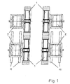
- the Fig. 1 shows a dynamometer with four test stand rollers 1.
- the test stand rollers 1 are driven or braked by respective prime movers 2.
- the bearings the prime movers 2 are designed either with smooth-running roller bearings or with hydrodynamic or hydrostatic bearings.
- Two of the drive machines 2 are slidably mounted on guide elements 11 in the direction of travel, so that the test bed can be adjusted to different wheelbases of motor vehicles to be tested.
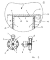
- the Fig. 2 bottom left shows a schematic side view of a dynamometer 1 with a vehicle wheel 3 shown schematically, which rolls on a roller casing 6 of the test bed roller 1. Furthermore, a roller base 4 is shown in this side view, the service cover 5 has.
- FIG. 2 Bottom right another plan view of the test stand roller 1 is shown.
- the test bed roller 1 is connected via a corresponding drive shaft with the drive machine 2.
- a section of the test stand roller is in an enlarged view A in the upper part of Fig. 2 shown in more detail.
- the test stand roller 1 has the roller casing 6, which has a casing outer surface 13. On this outer shell surface 13 usually rolls the vehicle 3 from.
- a corresponding material can additionally be provided on this outer shell surface 13 in order to simulate certain road surfaces.
- the roller casing 6 is connected to roller trays 4 which carry the roller casing 6.
- the roller trays 4 each have an insulating layer 8, 9 on respective outer sides 15. This insulating layer 8, 9 is firmly and directly adjacent to the respective roller base 4 connected.
- a service cover 5 is additionally shown, which is connectable via a screw 12 with the roller base 4.
- the insulating layer 8 may also be provided on the outside of the service cover 5. This allows a noise emission reduction over the total area of the roll tray 4.
- a further insulating layer 10 may be provided on a shell inner surface 14 in order to further reduce the noise emissions.
- the Fig. 3 shows in contrast to Fig. 2 the provision of corresponding counter-oscillators 16.
- Each counter-oscillator 16 can be arranged on the outside of the insulating layer 8, 9.
- the insulating layer 8, 9 is thus located between the respective outer side 15 of the respective roller base 4 and the corresponding counter-oscillator 16.
- the insulating material or the insulating layer 8, 9 is characterized in a sandwich-like arrangement between the roller base 4 and the counter-oscillator sixteenth This can further reduce noise emissions.
- the respective provided counter-oscillator 16 may be connected by means of corresponding screw with the respective support wall.
Landscapes
- Physics & Mathematics (AREA)
- General Physics & Mathematics (AREA)
- Measurement Of Mechanical Vibrations Or Ultrasonic Waves (AREA)
- Testing Of Devices, Machine Parts, Or Other Structures Thereof (AREA)
Description
- Die Erfindung betrifft einen Rollenprüfstand für Kraftfahrzeuge, der entsprechend angeordnete Isolierschichten aufweist, um die Geräuschemissionen beim Prüfen eines Kraftfahrzeugs zu minimieren.
- Rollenprüfstände finden allgemein in der Kraftfahrzeugtechnik ein weites Anwendungsfeld. So sind beispielsweise spezielle Prüfstände zum Ermitteln der Motorleistung auf dem Markt. Ebenso sind Rollenprüfstände für die Abgasmessung und für ABS-Systeme im Einsatz.
- Bei allen Prüfständen wird das Verhalten des Prüfstands speziell auf einen bestimmten Einsatzzweck abgestimmt. So muss beispielsweise ein Abgasprüfstand nicht unbedingt sehr hohe Leistungen absorbieren. Bei einem Leistungsprüfstand hingegen wird eine hohe Leistung gefordert. Das einheitliche Merkmal dieser Prüfstände ist, dass sich zumindest ein Fahrzeugrad auf einer Prüfstandsrolle dreht, wodurch das Fahren auf einer Fahrbahn simuliert wird.
- Während einer Fahrzeugentwicklung muss zudem beispielsweise die Geräuschemission im Innen- sowie Außenraum bei Konstantfahrt und beschleunigter Fahrt simuliert werden. Weiterhin sind Simulationen für unterschiedliche Straßenbeläge erforderlich. Diese Untersuchungen werden teilweise im Freifeld auf Versuchsstrecken, aber auch mehr und mehr auf Rollenprüfständen durchgeführt. Die Durchführung der Messung auf Rollenprüfständen hat den Vorteil, dass das Fahrzeug steht und sich quasi die Fahrbahn bewegt, wodurch die Anbringung der Messmittel am Fahrzeug wesentlich erleichtert wird. Dieser Vorteil bringt jedoch den Nachteil mit sich, dass in diesem Fall neben den Fahrzeug- auch die Prüfstandsgeräusche emittiert werden.
- Die Anforderungen an derartige NVH (Noise Vibration Harshness)-Prüfstände sind sehr hoch. Beispielsweise kann gefordert werden, dass bei einer simulierten Fahrgeschwindigkeit von 50 km/h das von dem Prüfstand verursachte Geräusch maximal 40 dB sein darf. Diese Fahrgeräuschprüfstände werden beispielsweise in Absorberhallen angeordnet.
- Die
JP 2006 105899 A - Es ist eine Aufgabe der Erfindung, einen Rollenprüfstand und eine Prüfstandsrolle für einen Rollenprüfstand zu schaffen, die nur geringe Geräuschemissionen verursachen.
- Diese Aufgabe wird gemäß den Merkmalen der unabhängigen Patentansprüche gelöst. Die abhängigen Patentansprüche betreffen vorteilhafte Ausführungsformen der Erfindung.
- Ein Rollenprüfstand für Kraftfahrzeuge kann zumindest eine Prüfstandsrolle aufweisen. Die Prüfstandsrolle kann zumindest einen Rollenboden und einen Rollenmantel aufweisen. Der Rollenboden kann den Rollenmantel tragen, wobei der Rollenmantel eine Mantelaußenfläche und eine Mantelinnenfläche aufweisen kann. Die Mantelaußenfläche kann mit einem Fahrzeugrad in Kontakt treten. Es kann weiterhin eine Isolierschicht zur Schall- und/oder Schwingungsdämpfung an dem Rollenboden vorgesehen sein.
- Es können ein oder bevorzugt zwei Rollenböden vorgesehen sein. In dem Fall, dass nur ein Rollenboden vorgesehen ist, muss dieser entsprechend stärker ausgebildet sein um den Rollenmantel zu tragen.
- Durch das Vorsehen einer Isolierschicht kann die Geräuschemission des Prüfstands stark vermindert werden. Insbesondere können durch die Isolierung die Geräuschemissionen stark vermindert werden, die durch das Abrollen des bzw. der Fahrzeugräder auf der bzw. den Prüfstandsrollen erzeugt werden.
- In diesem Zusammenhang ist festzuhalten, dass die Oberfläche der Prüfstandsrollen glatt oder rau (bspw. flammgespritzt) sein kann. Es ist jedoch auch denkbar, dass auf der Rollenoberfläche (Mantelaußenfläche) Schlagleisten, Kacheln oder andere Beläge vorgesehen sind, die bspw. einem Kopfsteinpflaster oder anderen Fahrbahnbelägen ähneln. Die abrollenden Fahrzeugräder und ebenso die prüfstandseitige Lagerung können den Prüfstand und speziell auch die Prüfstandsrollen zum Schwingen anregen. Jedes Fahrzeug "trampelt" auf der Prüfstandsrolle und erzeugt unterschiedliche Anregungsfrequenzen. Beim Auftreten von jeweiligen Resonanzen wird dieser Körperschall verstärkt und über eine akzeptable Grenze gehoben.
- Durch das erfindungsgemäße Vorsehen der Isolierschicht bzw. der Isolierschichten an den jeweiligen Außenseiten der Rollenböden kann die Geräuschemission ausreichend gedämpft werden. Die Isolierschicht kann aus einem zähelastischen Material gebildet sein, welches die durch die schwingenden Maschinenelemente erzeugte Schwingungsenergie in Wärme umsetzen kann und dadurch den Schwingungsvorgang bedämpft. Weiterhin ist festzustellen, dass Rollenkörper rollenspezifische Resonanzfrequenzen je nach Bauart der Prüfstandsrolle aufweisen. So ist beispielsweise der Rollenmantel durch seine gebogene Struktur ein relativ steifes Element, was zu höheren Resonanzfrequenzen führt. Der zumindest eine Rollenboden (Seitenwände) ist hingegen ein sehr großflächiges Element und hat dadurch eine niedrigere Resonanzfrequenz bzw. -frequenzen. Diese Rollenkörper werden nun durch prüfstandseitige Schwingungen angeregt und/oder durch das abrollende Fahrzeugrad. In Resonanzbereichen werden diese Schwingungen entsprechend verstärkt und damit wird eine relativ große Luftabstrahlleistung erzeugt. Durch das Aufbringen der Isolierschichten außen auf die Rollenböden können diese Geräuschemissionen stark vermindert werden.
- Ein Beispiel für das zähelastische Material ist etwa ein Gemisch von polymeren Pulvern auf PVC-Basis, Weichmachern, Additiven und Füllstoffen. Dieses Gemisch kann dann nochmals durch Erwärmung gehärtet werden. Derartige Materialien finden bspw. für den Unterbodenschutz von Fahrzeugen Verwendung.
- Zusätzlich zur ersten Isolierschicht, die an den jeweiligen Außenseiten der Rollenböden angeordnet ist oder alternativ dazu, kann eine zweite Isolierschicht vorgesehen sein, die an der Mantelinnenfläche des Rollenmantels vorgesehen ist. Durch das Vorsehen dieser zweiten Isolierschicht können die Geräuschemissionen weiter vermindert werden.
- Die ersten Isolierschichten und die zweite Isolierschicht sind fest und direkt anliegend mit den jeweiligen Trägerwänden (Rollenboden bzw. Rollenmantel) verbunden. Dadurch kann die Bedämpfung der jeweilig schwingenden Trägerwände optimiert werden.
- Es ist weiterhin möglich, einen oder mehrere Gegenschwinger vorzusehen. Diese Gegenschwinger können eine quasi doppelwandige Ausführung der Trägerwände vorsehen. Beispielsweise kann ein Gegenschwinger an der Außenseite der Isolierschicht vorgesehen sein, die an einem Rollenboden angeordnet ist. Dasselbe gilt für den auf der anderen Seite vorgesehenen Rollenboden.
- Zusätzlich, sofern an der Mantelinnenfläche des Rollenmantels eine Isolierschicht vorgesehen ist, kann auch an der Innenseite der Isolierschicht, die an der Mantelinnenfläche vorgesehen ist, ein entsprechender Gegenschwinger vorgesehen sein.
- Zur Optimierung der Verminderung der Geräuschemissionen können diese Gegenschwinger zumindest 25% der Masse der jeweiligen Trägerwand aufweisen. Im Fall, dass der Rollenboden beispielsweise mit einem 10 mm starken Material gebildet ist, kann der Gegenschwinger zumindest eine Wandstärke von 2,5 mm aufweisen. Dies gilt unter der Voraussetzung, dass sowohl die Trägerwand (Rollenboden) als auch der Gegenschwinger aus dem gleichen Material gebildet sind.
- Durch die vorgenannte doppelwandige Ausführung der Rollenböden und, sofern derart ausgeführt, des Rollenmantels ist das zähelastische Material (die Isolierschicht) zwischen zwei Wandungen angeordnet, wobei das zäh-elastische Material die Schwingungsarbeit aufnimmt und in Wärme umwandelt (bedämpft), wobei ein weiteres Abstrahlen der Schwingungen durch den jeweilig vorgesehenen Gegenschwinger weiter vermindert wird. Durch das Vorsehen der Gegenschwinger wie vorstehend erläutert kann folglich die Geräuschemission noch weiter vermindert werden.
- An dieser Stelle sei ausdrücklich erwähnt, dass die Isolierschicht an der Außenseite und/oder der Innenseite der Rollenböden angeordnet werden kann. Diese Isolierschichten können dann jeweils zusätzlich mit entsprechenden Gegenschwingern versehen sein. Diese Gegenschwinger sind dann jeweils derart angeordnet, dass ein entsprechendes Sandwich gebildet wird, welches das Isoliermaterial dazwischen aufnimmt.
- Zudem ist es auch möglich, dass das Isoliermaterial sowohl außen als auch innen am Rollenmantel vorgesehen ist. Das an dem Rollenmantel vorgesehene Isoliermaterial (außen und/oder innen) kann jeweils mit entsprechenden Gegenschwingern versehen werden, so dass diese Gegenschwinger, wie auch bei den Rollenböden, die Isolierschicht in eine Art Sandwich einschließen, wobei die Isolierschicht dann zwischen dem Gegenschwinger und dem Rollenmantel angeordnet ist.
- Die jeweiligen Gegenschwinger können mit entsprechenden Schraubverbindungen mit dem Rollenboden bzw. den Rollenböden und/ oder dem Rollenmantel verbunden sein.
- Die Rollenböden können weiterhin mit Service-Deckeln versehen sein. Das zu den Rollenböden vorstehend Erläuterte gilt ebenso für die Service-Deckel, wobei eine entsprechende Isolierung des Service-Deckels erfolgt.
- Zusammenfassend kann die Erfindung eine außerordentlich wirksame und effektive Geräuschemissionsverminderung durch das Vorsehen von entsprechenden Isolierschichten erzielen. Durch den zusätzlichen Einsatz von Gegenschwingern, die die Isolierschichten in eine Art Sandwich einschließen, kann das Geräuschemissionsverhalten weiter verbessert werden.
- Im Folgenden werden Ausführungsbeispiele der Erfindung anhand von schematischen Figuren näher erläutert. Es zeigen:
- Fig. 1
- eine Draufsicht auf einen Prüfstand für Kraftfahrzeuge,
- Fig. 2
- eine Seitenansicht einer Prüfstandsrolle mit darauf angeordnetem Fahrzeugrad und eine Ausschnittsvergrößerung A der Prüfstandsrolle in einer teilweisen Schnittdarstellung, und
- Fig. 3
- eine Seitenansicht einer Prüfstandsrolle mit darauf angeordnetem Fahrzeugrad und eine Ausschnittsvergrößerung B der Prüfstandsrolle mit Gegenschwingern in einer teilweisen Schnittdarstellung.
- Die
Fig. 1 zeigt einen Rollenprüfstand mit vier Prüfstandsrollen 1. Die Prüfstandsrollen 1 werden von entsprechenden Antriebsmaschinen 2 angetrieben bzw. gebremst. Die Lagerstellen der Antriebsmaschinen 2 sind entweder mit laufruhigen Rollenlagern oder mit hydrodynamischen bzw. hydrostatischen Lagern ausgeführt. Zwei der Antriebsmaschinen 2 sind auf Führungselementen 11 in Fahrtrichtung verschiebbar angebracht, damit der Prüfstand auf unterschiedliche Radstände der zu prüfenden Kraftfahrzeuge eingestellt werden kann. - Die
Fig. 2 zeigt unten links eine schematische Seitenansicht einer Prüfstandsrolle 1 mit einem schematisch dargestellten Fahrzeugrad 3, das auf einem Rollenmantel 6 der Prüfstandsrolle 1 abrollt. Weiterhin ist in dieser Seitenansicht ein Rollenboden 4 dargestellt, der Service-Deckel 5 aufweist. In derFig. 2 ist unten rechts eine weitere Draufsicht der Prüfstandsrolle 1 dargestellt. Die Prüfstandsrolle 1 ist über eine entsprechende Antriebswelle mit der Antriebsmaschine 2 verbunden. Ein Abschnitt der Prüfstandsrolle ist in einer vergrößerten Darstellung A im oberen Teil derFig. 2 genauer dargestellt. Die Prüfstandsrolle 1 weist den Rollenmantel 6 auf, der eine Mantelaußenfläche 13 aufweist. Auf dieser Mantelaußenfläche 13 rollt üblicherweise das Fahrzeugrad 3 ab. Wie vorangehend schon erläutert, kann auf dieser Mantelaußenfläche 13 zusätzlich noch ein entsprechendes Material vorgesehen sein, um bestimmte Straßenoberflächen zu simulieren. - Der Rollenmantel 6 ist mit Rollenböden 4 verbunden, die den Rollenmantel 6 tragen. Die Rollenböden 4 weisen auf jeweiligen Außenseiten 15 jeweils eine Isolierschicht 8, 9 auf. Diese Isolierschicht 8, 9 ist fest und direkt anliegend mit dem jeweiligen Rollenboden 4 verbunden. In der vergrößerten Darstellung A ist zusätzlich ein Service-Deckel 5 dargestellt, der über eine Schraube 12 mit dem Rollenboden 4 verbindbar ist. Zusätzlich zum Vorsehen der Isolierschicht 8, 9 an der Außenseite 15 des Rollenbodens 4 kann die Isolierschicht 8 auch an der Außenseite des Service-Deckels 5 vorgesehen sein. Dies erlaubt eine Geräuschemissionsreduzierung über die Gesamtfläche des Rollenbodens 4.
- An einer Mantelinnenfläche 14 kann zusätzlich eine weitere Isolierschicht 10 vorgesehen sein, um die Geräuschemissionen weiter zu vermindern.
- Die
Fig. 3 zeigt im Unterschied zurFig. 2 das Vorsehen von entsprechenden Gegenschwingern 16. - Es können jeweilige Gegenschwinger 16 außen an der Isolierschicht 8, 9 angeordnet werden. Die Isolierschicht 8, 9 befindet sich damit zwischen der jeweiligen Außenseite 15 des jeweiligen Rollenbodens 4 und dem entsprechend vorgesehenen Gegenschwinger 16. Das Isoliermaterial bzw. die Isolierschicht 8, 9 befindet sich dadurch in einer sandwich-artigen Anordnung zwischen dem Rollenboden 4 und dem Gegenschwinger 16. Dadurch kann die Geräuschemission weiter vermindert werden.
- Darüber hinaus ist es zudem möglich, einen Gegenschwinger 16 an der Mantelinnenfläche 14 vorzusehen, wobei zwischen dem Gegenschwinger 16 und der Mantelinnenfläche 14 die Isolierschicht 10 vorgesehen ist.
- Die jeweilig vorgesehenen Gegenschwinger 16 können mittels entsprechenden Verschraubungen mit der jeweiligen Trägerwand verbunden sein.
- Die vorstehenden Ausführungsformen und Merkmale können in beliebiger Weise miteinander kombiniert werden.
Claims (11)
- Rollenprüfstand für Kraftfahrzeuge, mit- zumindest einer Prüfstandsrolle (1), die zumindest einen Rollenboden (4) und einen Rollenmantel (6) aufweist, wobei der Rollenboden (4) den Rollenmantel (6) trägt, der Rollenmantel (6) eine Mantelaußenfläche (13) und eine Mantelinnenfläche (14) aufweist und die Mantelaußenfläche (13) für ein in Kontakt treten mit einem Fahrzeugrad (3) ausgebildet ist, und- einer ersten Isolierschicht (8, 9) zur Schall- und/oder Schwingungsdämpfung, die an zumindest einem Rollenboden (4) angeordnet ist,dadurch gekennzeichnet, dass
ein Gegenschwinger (16) auf der ersten Isolierschicht (8, 9) angeordnet ist und der Gegenschwinger (16) mit dem
Rollenboden (4) und dem dazwischen angeordneten Isoliermaterial (8, 9, 10) ein Sandwich bildet, wobei der Gegenschwinger (16) fest und direkt anliegend mit dem Isoliermaterial (8, 9, 10) in Verbindung steht. - Rollenprüfstand nach Anspruch 1, dadurch gekennzeichnet, dass die erste Isolierschicht (8, 9) an der jeweiligen Außenseite (15) des Rollenbodens (4) angeordnet ist.
- Rollenprüfstand nach Anspruch 1 oder 2, dadurch gekennzeichnet, dass die Isolierschicht (8, 9) fest und direkt anliegend mit der Außenseite (15) des Rollenbodens (4) verbunden ist.
- Rollenprüfstand nach zumindest einem der Ansprüche 1 bis 3, dadurch gekennzeichnet, dass zwei Rollenböden (4) vorgesehen sind.
- Rollenprüfstand nach zumindest einem der Ansprüche 1 bis 4, dadurch gekennzeichnet, dass eine zweite Isolierschicht (10) zur Schall- und Schwingungsdämpfung an der Mantellnnenfläche (14) des Rollenmantels (6) vorgesehen ist.
- Rollenprüfstand nach Anspruch 5, dadurch gekennzeichnet, dass die zweite Isolierschicht (10) fest und direkt anliegend mit der Mantelinnenfläche (14) des Rollenmantels (6) verbunden ist.
- Rollenprüfstand nach zumindest einem der Ansprüche 1 bis 6, dadurch gekennzeichnet, dass ein Gegenschwinger (16) auf der zweiten Isolierschicht (10) angeordnet ist.
- Rollenprüfstand nach zumindest einem der Ansprüche 1 bis 7, dadurch gekennzeichnet, dass der Gegenschwinger (16) mit dem Rollenboden (4) und/oder dem Rollenmantel (6) verschraubt ist.
- Rollenprüfstand nach zumindest einem der Ansprüche 7 bis 8, dadurch gekennzeichnet, dass der Gegenschwinger (16) zumindest 25% der Masse der jeweiligen Trägerwand aufweist.
- Rollenprüfstand nach zumindest einem der Ansprüche 1 bis 9, wobei die Rollenböden (4) Tragstege aufweisen.
- Prüfstandrolle des Rollenprüfstandes nach zumindest einem der Ansprüche 1 bis 10.
Applications Claiming Priority (1)
| Application Number | Priority Date | Filing Date | Title |
|---|---|---|---|
| DE200710048315 DE102007048315A1 (de) | 2007-10-09 | 2007-10-09 | Rollenprüfstand für Kraftfahrzeuge |
Publications (3)
| Publication Number | Publication Date |
|---|---|
| EP2048486A2 EP2048486A2 (de) | 2009-04-15 |
| EP2048486A3 EP2048486A3 (de) | 2011-01-05 |
| EP2048486B1 true EP2048486B1 (de) | 2012-05-30 |
Family
ID=40221069
Family Applications (1)
| Application Number | Title | Priority Date | Filing Date |
|---|---|---|---|
| EP20080017726 Active EP2048486B1 (de) | 2007-10-09 | 2008-10-09 | Rollenprüfstand für Kraftfahrzeuge |
Country Status (2)
| Country | Link |
|---|---|
| EP (1) | EP2048486B1 (de) |
| DE (1) | DE102007048315A1 (de) |
Cited By (1)
| Publication number | Priority date | Publication date | Assignee | Title |
|---|---|---|---|---|
| DE102022210724A1 (de) | 2022-10-11 | 2024-04-11 | Aip Gmbh & Co. Kg | Universalprüfstand und Verfahren zur Geräusch- und Vibrationsmessung |
Families Citing this family (3)
| Publication number | Priority date | Publication date | Assignee | Title |
|---|---|---|---|---|
| FR2946744B1 (fr) * | 2009-06-16 | 2011-07-22 | Createch Composites | Rouleau pour freinometre |
| DE102011077321B4 (de) | 2011-06-09 | 2020-05-14 | Aip Gmbh & Co. Kg | Rolle für Bandeinheit |
| DE102018112940A1 (de) * | 2018-05-30 | 2019-12-05 | Renk Test System Gmbh | Rollenprüfstand |
Family Cites Families (2)
| Publication number | Priority date | Publication date | Assignee | Title |
|---|---|---|---|---|
| DE2852828C2 (de) * | 1978-12-07 | 1981-02-26 | Teroson Gmbh, 6900 Heidelberg | Verfahren zur Herstellung einer körperschalldämpfenden Beschichtung |
| JP4496054B2 (ja) * | 2004-10-08 | 2010-07-07 | 株式会社小野測器 | シャシーダイナモメータ |
-
2007
- 2007-10-09 DE DE200710048315 patent/DE102007048315A1/de not_active Ceased
-
2008
- 2008-10-09 EP EP20080017726 patent/EP2048486B1/de active Active
Cited By (1)
| Publication number | Priority date | Publication date | Assignee | Title |
|---|---|---|---|---|
| DE102022210724A1 (de) | 2022-10-11 | 2024-04-11 | Aip Gmbh & Co. Kg | Universalprüfstand und Verfahren zur Geräusch- und Vibrationsmessung |
Also Published As
| Publication number | Publication date |
|---|---|
| DE102007048315A1 (de) | 2009-04-16 |
| EP2048486A2 (de) | 2009-04-15 |
| EP2048486A3 (de) | 2011-01-05 |
Similar Documents
| Publication | Publication Date | Title |
|---|---|---|
| Xu et al. | Experimental study on driver seat vibration characteristics of crawler-type combine harvester | |
| DE102010016587A1 (de) | Radsatz | |
| DE19822582B4 (de) | Aktive Geräuschunterdrückung für lärmabstrahlende Flächen | |
| DE102019113004A1 (de) | Erfassung eines reibungsbremsenfehlers | |
| DE102004046200A1 (de) | Mobiler Prüfstand zur Bestimmung der Schalldämmung oder Einfügungsdämmung eines Prüfobjekts | |
| EP2048486A2 (de) | Rollenprüfstand für Kraftfahrzeuge | |
| DE102008008061B4 (de) | Prüfstand | |
| Tosun et al. | Investigation and refinement of gearbox whine noise | |
| EP3549239A1 (de) | Elektromotor für eine antriebseinheit eines antriebsstrangprüfstands | |
| EP2470873B1 (de) | Prüfstand mit schwingungstilger | |
| Douville et al. | On-resonance transmissibility methodology for quantifying the structure-borne road noise of an automotive suspension assembly | |
| Burdzik et al. | Research of vibration distribution in vehicle constructive | |
| EP3966544B1 (de) | Verfahren und prüfstand zur bestimmung von reifeneigenschaften | |
| DE102010044058A1 (de) | Vorrichtung zur Bestimmung von auf Kraftfahrzeuge in einem Windkanal einwirkenden Kräften und Momenten | |
| DE3926281C2 (de) | Geräuschprüfstand für Pkw-Getriebe | |
| DE102014106701B4 (de) | Verfahren zur Bestimmung einer statischen Biegesteifigkeit eines Objekts aus dynamischen Beschleunigungsmessungen nach einer Schwingungsanregung des Objekts | |
| DE102010016329A1 (de) | Vorrichtung und Verfahren zum Bestimmen des Schwingungsverhaltens eines Bremsbelags im Kraftfahrzeugbereich | |
| Abd-El-Tawwab et al. | Characteristics of agriculture tractor interior noise | |
| DE102008011285A1 (de) | Aktiver Schallblocker | |
| AT525968B1 (de) | Verfahren und System zum Bewerten eines Elektromotors eines elektrischen Antriebssystems eines Kraftfahrzeugs hinsichtlich seiner im Betrieb hör- und/oder spürbaren Schwingungen | |
| Bao et al. | Numerical and experimental investigations of multiple resonators on reducing tyre cavity resonance noise | |
| DE102022004593B3 (de) | Lauftrommel eines Rollenprüfstandes für schwere Fahrzeuge | |
| Channamaneni et al. | A systematic approach towards engine mounting system vibration isolation performance validation in commercial vehicles | |
| DE102021130208A1 (de) | Schalldämpfende Anordnung, ein Ring zum Schalldämpfen und ein Verfahren | |
| DE102005044987B4 (de) | Zugmitteltrieb für eine Brennkraftmaschine |
Legal Events
| Date | Code | Title | Description |
|---|---|---|---|
| PUAI | Public reference made under article 153(3) epc to a published international application that has entered the european phase |
Free format text: ORIGINAL CODE: 0009012 |
|
| AK | Designated contracting states |
Kind code of ref document: A2 Designated state(s): AT BE BG CH CY CZ DE DK EE ES FI FR GB GR HR HU IE IS IT LI LT LU LV MC MT NL NO PL PT RO SE SI SK TR |
|
| AX | Request for extension of the european patent |
Extension state: AL BA MK RS |
|
| PUAL | Search report despatched |
Free format text: ORIGINAL CODE: 0009013 |
|
| AK | Designated contracting states |
Kind code of ref document: A3 Designated state(s): AT BE BG CH CY CZ DE DK EE ES FI FR GB GR HR HU IE IS IT LI LT LU LV MC MT NL NO PL PT RO SE SI SK TR |
|
| AX | Request for extension of the european patent |
Extension state: AL BA MK RS |
|
| 17P | Request for examination filed |
Effective date: 20110705 |
|
| AKX | Designation fees paid |
Designated state(s): AT BE BG CH CY CZ DE DK EE ES FI FR GB GR HR HU IE IS IT LI LT LU LV MC MT NL NO PL PT RO SE SI SK TR |
|
| GRAP | Despatch of communication of intention to grant a patent |
Free format text: ORIGINAL CODE: EPIDOSNIGR1 |
|
| GRAS | Grant fee paid |
Free format text: ORIGINAL CODE: EPIDOSNIGR3 |
|
| GRAA | (expected) grant |
Free format text: ORIGINAL CODE: 0009210 |
|
| AK | Designated contracting states |
Kind code of ref document: B1 Designated state(s): AT BE BG CH CY CZ DE DK EE ES FI FR GB GR HR HU IE IS IT LI LT LU LV MC MT NL NO PL PT RO SE SI SK TR |
|
| REG | Reference to a national code |
Ref country code: GB Ref legal event code: FG4D Free format text: NOT ENGLISH |
|
| REG | Reference to a national code |
Ref country code: CH Ref legal event code: EP |
|
| REG | Reference to a national code |
Ref country code: AT Ref legal event code: REF Ref document number: 560280 Country of ref document: AT Kind code of ref document: T Effective date: 20120615 |
|
| REG | Reference to a national code |
Ref country code: IE Ref legal event code: FG4D Free format text: LANGUAGE OF EP DOCUMENT: GERMAN |
|
| REG | Reference to a national code |
Ref country code: DE Ref legal event code: R096 Ref document number: 502008007293 Country of ref document: DE Effective date: 20120802 |
|
| REG | Reference to a national code |
Ref country code: NL Ref legal event code: VDEP Effective date: 20120530 |
|
| REG | Reference to a national code |
Ref country code: LT Ref legal event code: MG4D Effective date: 20120530 |
|
| PG25 | Lapsed in a contracting state [announced via postgrant information from national office to epo] |
Ref country code: CY Free format text: LAPSE BECAUSE OF FAILURE TO SUBMIT A TRANSLATION OF THE DESCRIPTION OR TO PAY THE FEE WITHIN THE PRESCRIBED TIME-LIMIT Effective date: 20120530 Ref country code: FI Free format text: LAPSE BECAUSE OF FAILURE TO SUBMIT A TRANSLATION OF THE DESCRIPTION OR TO PAY THE FEE WITHIN THE PRESCRIBED TIME-LIMIT Effective date: 20120530 Ref country code: LT Free format text: LAPSE BECAUSE OF FAILURE TO SUBMIT A TRANSLATION OF THE DESCRIPTION OR TO PAY THE FEE WITHIN THE PRESCRIBED TIME-LIMIT Effective date: 20120530 Ref country code: SE Free format text: LAPSE BECAUSE OF FAILURE TO SUBMIT A TRANSLATION OF THE DESCRIPTION OR TO PAY THE FEE WITHIN THE PRESCRIBED TIME-LIMIT Effective date: 20120530 Ref country code: IS Free format text: LAPSE BECAUSE OF FAILURE TO SUBMIT A TRANSLATION OF THE DESCRIPTION OR TO PAY THE FEE WITHIN THE PRESCRIBED TIME-LIMIT Effective date: 20120930 Ref country code: NO Free format text: LAPSE BECAUSE OF FAILURE TO SUBMIT A TRANSLATION OF THE DESCRIPTION OR TO PAY THE FEE WITHIN THE PRESCRIBED TIME-LIMIT Effective date: 20120830 |
|
| PG25 | Lapsed in a contracting state [announced via postgrant information from national office to epo] |
Ref country code: HR Free format text: LAPSE BECAUSE OF FAILURE TO SUBMIT A TRANSLATION OF THE DESCRIPTION OR TO PAY THE FEE WITHIN THE PRESCRIBED TIME-LIMIT Effective date: 20120530 Ref country code: SI Free format text: LAPSE BECAUSE OF FAILURE TO SUBMIT A TRANSLATION OF THE DESCRIPTION OR TO PAY THE FEE WITHIN THE PRESCRIBED TIME-LIMIT Effective date: 20120530 Ref country code: GR Free format text: LAPSE BECAUSE OF FAILURE TO SUBMIT A TRANSLATION OF THE DESCRIPTION OR TO PAY THE FEE WITHIN THE PRESCRIBED TIME-LIMIT Effective date: 20120831 Ref country code: LV Free format text: LAPSE BECAUSE OF FAILURE TO SUBMIT A TRANSLATION OF THE DESCRIPTION OR TO PAY THE FEE WITHIN THE PRESCRIBED TIME-LIMIT Effective date: 20120530 |
|
| PG25 | Lapsed in a contracting state [announced via postgrant information from national office to epo] |
Ref country code: RO Free format text: LAPSE BECAUSE OF FAILURE TO SUBMIT A TRANSLATION OF THE DESCRIPTION OR TO PAY THE FEE WITHIN THE PRESCRIBED TIME-LIMIT Effective date: 20120530 Ref country code: NL Free format text: LAPSE BECAUSE OF FAILURE TO SUBMIT A TRANSLATION OF THE DESCRIPTION OR TO PAY THE FEE WITHIN THE PRESCRIBED TIME-LIMIT Effective date: 20120530 Ref country code: SK Free format text: LAPSE BECAUSE OF FAILURE TO SUBMIT A TRANSLATION OF THE DESCRIPTION OR TO PAY THE FEE WITHIN THE PRESCRIBED TIME-LIMIT Effective date: 20120530 Ref country code: EE Free format text: LAPSE BECAUSE OF FAILURE TO SUBMIT A TRANSLATION OF THE DESCRIPTION OR TO PAY THE FEE WITHIN THE PRESCRIBED TIME-LIMIT Effective date: 20120530 Ref country code: DK Free format text: LAPSE BECAUSE OF FAILURE TO SUBMIT A TRANSLATION OF THE DESCRIPTION OR TO PAY THE FEE WITHIN THE PRESCRIBED TIME-LIMIT Effective date: 20120530 |
|
| PG25 | Lapsed in a contracting state [announced via postgrant information from national office to epo] |
Ref country code: IT Free format text: LAPSE BECAUSE OF FAILURE TO SUBMIT A TRANSLATION OF THE DESCRIPTION OR TO PAY THE FEE WITHIN THE PRESCRIBED TIME-LIMIT Effective date: 20120530 Ref country code: PL Free format text: LAPSE BECAUSE OF FAILURE TO SUBMIT A TRANSLATION OF THE DESCRIPTION OR TO PAY THE FEE WITHIN THE PRESCRIBED TIME-LIMIT Effective date: 20120530 Ref country code: PT Free format text: LAPSE BECAUSE OF FAILURE TO SUBMIT A TRANSLATION OF THE DESCRIPTION OR TO PAY THE FEE WITHIN THE PRESCRIBED TIME-LIMIT Effective date: 20121001 |
|
| PLBE | No opposition filed within time limit |
Free format text: ORIGINAL CODE: 0009261 |
|
| STAA | Information on the status of an ep patent application or granted ep patent |
Free format text: STATUS: NO OPPOSITION FILED WITHIN TIME LIMIT |
|
| BERE | Be: lapsed |
Owner name: MAHA-AIP G.M.B.H. & CO. KG Effective date: 20121031 |
|
| PG25 | Lapsed in a contracting state [announced via postgrant information from national office to epo] |
Ref country code: ES Free format text: LAPSE BECAUSE OF FAILURE TO SUBMIT A TRANSLATION OF THE DESCRIPTION OR TO PAY THE FEE WITHIN THE PRESCRIBED TIME-LIMIT Effective date: 20120910 |
|
| 26N | No opposition filed |
Effective date: 20130301 |
|
| PG25 | Lapsed in a contracting state [announced via postgrant information from national office to epo] |
Ref country code: MC Free format text: LAPSE BECAUSE OF NON-PAYMENT OF DUE FEES Effective date: 20121031 |
|
| REG | Reference to a national code |
Ref country code: CH Ref legal event code: PL |
|
| GBPC | Gb: european patent ceased through non-payment of renewal fee |
Effective date: 20121009 |
|
| REG | Reference to a national code |
Ref country code: DE Ref legal event code: R097 Ref document number: 502008007293 Country of ref document: DE Effective date: 20130301 |
|
| REG | Reference to a national code |
Ref country code: IE Ref legal event code: MM4A |
|
| PG25 | Lapsed in a contracting state [announced via postgrant information from national office to epo] |
Ref country code: CH Free format text: LAPSE BECAUSE OF NON-PAYMENT OF DUE FEES Effective date: 20121031 Ref country code: BE Free format text: LAPSE BECAUSE OF NON-PAYMENT OF DUE FEES Effective date: 20121031 Ref country code: GB Free format text: LAPSE BECAUSE OF NON-PAYMENT OF DUE FEES Effective date: 20121009 Ref country code: IE Free format text: LAPSE BECAUSE OF NON-PAYMENT OF DUE FEES Effective date: 20121009 Ref country code: BG Free format text: LAPSE BECAUSE OF FAILURE TO SUBMIT A TRANSLATION OF THE DESCRIPTION OR TO PAY THE FEE WITHIN THE PRESCRIBED TIME-LIMIT Effective date: 20120830 Ref country code: LI Free format text: LAPSE BECAUSE OF NON-PAYMENT OF DUE FEES Effective date: 20121031 |
|
| PG25 | Lapsed in a contracting state [announced via postgrant information from national office to epo] |
Ref country code: MT Free format text: LAPSE BECAUSE OF FAILURE TO SUBMIT A TRANSLATION OF THE DESCRIPTION OR TO PAY THE FEE WITHIN THE PRESCRIBED TIME-LIMIT Effective date: 20120530 |
|
| PG25 | Lapsed in a contracting state [announced via postgrant information from national office to epo] |
Ref country code: TR Free format text: LAPSE BECAUSE OF FAILURE TO SUBMIT A TRANSLATION OF THE DESCRIPTION OR TO PAY THE FEE WITHIN THE PRESCRIBED TIME-LIMIT Effective date: 20120530 |
|
| PG25 | Lapsed in a contracting state [announced via postgrant information from national office to epo] |
Ref country code: LU Free format text: LAPSE BECAUSE OF NON-PAYMENT OF DUE FEES Effective date: 20121009 |
|
| PG25 | Lapsed in a contracting state [announced via postgrant information from national office to epo] |
Ref country code: HU Free format text: LAPSE BECAUSE OF FAILURE TO SUBMIT A TRANSLATION OF THE DESCRIPTION OR TO PAY THE FEE WITHIN THE PRESCRIBED TIME-LIMIT Effective date: 20081009 |
|
| REG | Reference to a national code |
Ref country code: AT Ref legal event code: MM01 Ref document number: 560280 Country of ref document: AT Kind code of ref document: T Effective date: 20131009 |
|
| PG25 | Lapsed in a contracting state [announced via postgrant information from national office to epo] |
Ref country code: AT Free format text: LAPSE BECAUSE OF NON-PAYMENT OF DUE FEES Effective date: 20131009 |
|
| REG | Reference to a national code |
Ref country code: FR Ref legal event code: PLFP Year of fee payment: 8 |
|
| REG | Reference to a national code |
Ref country code: FR Ref legal event code: PLFP Year of fee payment: 9 |
|
| REG | Reference to a national code |
Ref country code: FR Ref legal event code: PLFP Year of fee payment: 10 |
|
| PGFP | Annual fee paid to national office [announced via postgrant information from national office to epo] |
Ref country code: FR Payment date: 20171023 Year of fee payment: 10 |
|
| REG | Reference to a national code |
Ref country code: DE Ref legal event code: R082 Ref document number: 502008007293 Country of ref document: DE Representative=s name: MERH-IP MATIAS ERNY REICHL HOFFMANN PATENTANWA, DE Ref country code: DE Ref legal event code: R081 Ref document number: 502008007293 Country of ref document: DE Owner name: AIP GMBH & CO. KG, DE Free format text: FORMER OWNER: MAHA-AIP GMBH & CO. KG, 87490 HALDENWANG, DE |
|
| PG25 | Lapsed in a contracting state [announced via postgrant information from national office to epo] |
Ref country code: FR Free format text: LAPSE BECAUSE OF NON-PAYMENT OF DUE FEES Effective date: 20181031 |
|
| PGFP | Annual fee paid to national office [announced via postgrant information from national office to epo] |
Ref country code: CZ Payment date: 20210929 Year of fee payment: 14 |
|
| PG25 | Lapsed in a contracting state [announced via postgrant information from national office to epo] |
Ref country code: CZ Free format text: LAPSE BECAUSE OF NON-PAYMENT OF DUE FEES Effective date: 20221009 |
|
| PGFP | Annual fee paid to national office [announced via postgrant information from national office to epo] |
Ref country code: DE Payment date: 20251031 Year of fee payment: 18 |