EP2048497A1 - Chromatographiesäule und verfahren zur herstellung davon - Google Patents
Chromatographiesäule und verfahren zur herstellung davon Download PDFInfo
- Publication number
- EP2048497A1 EP2048497A1 EP07792504A EP07792504A EP2048497A1 EP 2048497 A1 EP2048497 A1 EP 2048497A1 EP 07792504 A EP07792504 A EP 07792504A EP 07792504 A EP07792504 A EP 07792504A EP 2048497 A1 EP2048497 A1 EP 2048497A1
- Authority
- EP
- European Patent Office
- Prior art keywords
- substrate
- pillars
- column
- pillar
- recess
- Prior art date
- Legal status (The legal status is an assumption and is not a legal conclusion. Google has not performed a legal analysis and makes no representation as to the accuracy of the status listed.)
- Granted
Links
Images


Classifications
-
- G—PHYSICS
- G01—MEASURING; TESTING
- G01N—INVESTIGATING OR ANALYSING MATERIALS BY DETERMINING THEIR CHEMICAL OR PHYSICAL PROPERTIES
- G01N30/00—Investigating or analysing materials by separation into components using adsorption, absorption or similar phenomena or using ion-exchange, e.g. chromatography or field flow fractionation
- G01N30/02—Column chromatography
- G01N30/60—Construction of the column
- G01N30/6095—Micromachined or nanomachined, e.g. micro- or nanosize
-
- G—PHYSICS
- G01—MEASURING; TESTING
- G01N—INVESTIGATING OR ANALYSING MATERIALS BY DETERMINING THEIR CHEMICAL OR PHYSICAL PROPERTIES
- G01N30/00—Investigating or analysing materials by separation into components using adsorption, absorption or similar phenomena or using ion-exchange, e.g. chromatography or field flow fractionation
- G01N30/02—Column chromatography
- G01N30/50—Conditioning of the sorbent material or stationary liquid
- G01N30/52—Physical parameters
-
- G—PHYSICS
- G01—MEASURING; TESTING
- G01N—INVESTIGATING OR ANALYSING MATERIALS BY DETERMINING THEIR CHEMICAL OR PHYSICAL PROPERTIES
- G01N30/00—Investigating or analysing materials by separation into components using adsorption, absorption or similar phenomena or using ion-exchange, e.g. chromatography or field flow fractionation
- G01N30/02—Column chromatography
- G01N30/50—Conditioning of the sorbent material or stationary liquid
- G01N30/52—Physical parameters
- G01N2030/524—Physical parameters structural properties
- G01N2030/525—Physical parameters structural properties surface properties, e.g. porosity
Definitions
- the present invention relates to a column used for chromatography and a manufacturing method for the same.
- liquid chromatography has been used as a means for analyzing materials contained in a sample.
- Liquid chromatography is in general a separation method using interaction between the sample dissolved in a solution and a functional group modified on a surface of a solid.
- the liquid chromatography employs a column prepared by filling a stainless steel tube (SUS tube), a glass tube, or the like having thin diameter with porous fine particles, on which the functional group is modified.
- the sample is introduced into the column.
- the liquid serving as a carrier is introduced, the sample is eluted out of the column while interacting with a solid surface.
- Patent Document 1 discloses a configuration for forming a flow path provided with baffle plates by etching. Further, also described therein is a construction for forming porous aluminum oxide by anodic oxidation after filling the flow path formed on a silicon substrate with aluminum. Further, a configuration for charging the flow path with porous silicon oxide (SiO 2 ) or the like is also provided.
- Patent Document 1 Japanese Patent Laid-open Publication No. H2-310467
- the conventional packed column is charged with particles having a certain particle diameter distribution.
- particles having different particles shapes are present adjacent to each other, there is a variation in inter-particle distance, so that a sample solution for a separation is diluted in a nonuniform manner.
- moving rates of the sample solution in the column are also different.
- a peak width is enlarged, resulting in deterioration of separation efficiency.
- the method of forming the uniform flow path has a drawback in that closest-packing is difficult.
- the separation efficiency is improved by interaction with a separation target material. Accordingly, a carrier having a large effective surface area for the separation target material is utilized for better separation efficiency.
- a sufficient surface area capable of interacting with the separation target material is difficult to obtain.
- the present invention provides a chromatography column having a good separation efficiency; and a manufacturing method thereof.
- a column for chromatography including: a first substrate having a plurality of pillars formed on one surface thereof; and a second substrate bonded to the one surface of the first substrate and constituting a flow path together with the plurality of pillars formed on the first substrate, wherein at least a surface of each pillar is formed in a porous shape.
- the plurality of pillars may be formed in a recess provided on the first substrate, and the second substrate may be formed in a flat plate shape and bonded to the first substrate so as to cover the plurality of pillars.
- the plurality of pillars may be formed in a recess provided on the first substrate, and a recess and a plurality of pillars corresponding to the recess and the plurality of pillars formed on the first substrate respectively may be formed on the second substrate.
- the second substrate may be provided with a recess corresponding to the plurality of pillars.
- the pillar may be formed in the porous shape from the surface to the center thereof so that the entire pillar may be formed in the porous shape.
- the plurality of pillars may be spaced apart from each other in the flow path at a substantially same spacing.
- Spacings of the pillars and/or diameters of the pillars may be different for each of regions inside the flow path.
- the first substrate may be made up of a silicon substrate.
- a manufacturing method of a column for chromatography including: a mask forming process for forming a mask, which is provided with a pattern corresponding to a pillar, on one surface of a first substrate; a pillar forming process for forming the pillar by etching the first substrate through the mask; a porousifying process for forming at least a surface of the pillar in a porous shape; a mask removing process for removing the mask formed on the first substrate; and a substrate bonding process for bonding a second substrate to the first substrate.
- At least the surface of the pillar may be formed in the porous shape by anodic oxidation.
- the entire pillar may be formed in the porous shape by anodic oxidation.
- the pillar itself formed on the first substrate may be porousified, so that at least the surface of the pillar may be formed in the porous shape.
- the pillars may be spaced apart from each other at a substantially same spacing.
- spacings of the pillars and/or diameters of the pillars may be different for each of regions in the flow path.
- the first substrate may be made up of a silicon substrate.
- a chromatography column capable of suppressing diffusion of a separation target material within a flow path by a uniform flow therein by forming pillars at an almost same spacing and having a high separation efficiency by porousifying at least the surfaces of the pillars after forming them by an etching process, and a manufacturing method thereof.
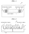
- the column 10 for chromatography is illustrated in Fig. 1 and Fig. 2 which is a cross sectional view taken along a line A-A of Fig. 1 .
- the column 10 in accordance with the present embodiment is used, for example, in liquid chromatography.
- illustration of a second substrate 12 is omitted for the simplicity of explanation of a recess 21 and pillars 22.
- the column 10 in accordance with the present embodiment includes, as shown in Figs. 1 and 2 , a first substrate 11 and the second substrate 12.
- the recess 21 and a plurality of pillars 22 are formed on the first substrate 11.
- the recess 21, the pillars 22, the inlet opening 12a and the outlet opening 12b constitute a flow path 13.
- the sample is introduced to the inlet opening 12a and discharged out from the outlet opening 12b after passing through the pillars 22.
- the first substrate 11 is made up of, e.g., a silicon substrate.
- the recess 21 and the pillars 22 are formed on the top surface of the substrate 11.
- the second substrate 12 is air-tightly bonded to the top surface of the first substrate 11 on which the recess 21 and the pillars 22 are formed.
- the recess 21 is formed in a substantially rectangular cross sectional shape, and it has a rectangular shape whose both ends are formed in trapezoid shapes when viewed from the top thereof.
- the width of the recess 21 ranges from, e.g., about 50 ⁇ m to 2000 ⁇ m, desirably about 300 ⁇ m to 500 ⁇ m, and the length of the recess 21 is in the range of, e.g., about 10 mm to 1 m, desirably about 30 mm and 500 mm.
- the inlet opening 12a for introducing the sample and the outlet opening 12b for discharging the sample are formed on the top surface of the recess 21 at both ends thereof.
- both ends of the recess 21 are formed in the trapezoid shapes and they are enlarged toward the center of the recess 21.
- the recess 21 has, at its bottom surface, a porous layer 21a formed in a porous shape, like the surfaces of the pillars 22.
- the shape of the recess 21 is not limited to the rectangular shape but it can be formed in, e.g., a spiral shape, a zigzag shape, or the like.
- the shape of the recess can be appropriately selected depending on the size of the first substrate 11, the required length of the flow path 13, or the like.
- Each of the plurality of pillars 22 are formed in, e.g., a columnar shape.
- the pillars 22 are formed by etching the first substrate 11, as will be described later.
- the pillars 22 are distanced apart from each other at a substantially same spacing.
- the respective pillars 22 are arranged with the appropriate spacing maintained therebetween such that a desired pressure is obtained.
- the diameter of the pillar 22 is set to range from about 1 ⁇ m to 10 ⁇ m, desirably about 4 ⁇ m to 7 ⁇ m
- the height of the pillar 22 is set to be in the range of, e.g., about 10 ⁇ m to 300 ⁇ m, desirably about 40 ⁇ m to 60 ⁇ m.
- the adjacent pillars 22 are spaced apart from each other by, e.g., about 1 ⁇ m to 10 ⁇ m, desirably about 1.5 ⁇ m to 3 ⁇ m.
- the flow of the sample is facilitated, so that generation of a turbulent flow in the flow path 13 can be suppressed successfully.
- a pressure can be reduced when introducing the sample.
- a porous layer 22a having a porous shape is formed on the surface of the pillar 22 by anodic oxidization, as will be described later.
- porous layer 21a formed on the bottom surface and the lateral surface of the recess 21 and the porous layer 22a of the pillar 22 are formed as one body in a single process to be described later, they are assigned different reference numerals for the convenience of explanation.
- a functional group may be introduced into the porous layer 21a of the recess 21 and the porous layer 22a of the pillar 22.
- the introduced functional group can be appropriately selected depending on a sample to be analyzed.
- the selected functional group may be, for example, an ion-exchange group, a hydrophobic group, a hydrophilic group, an affinitive group or the like and is used as a filler for the liquid chromatography.
- the ion functional group may include an anion-exchange group represented by an amino group, a mono-substituted amino group, a disubstituted amino group, a tri-substituted amino group, or a cation-exchange group represented by a carboxyl group, a sulfonic acid group.
- the hydrophobic group may be an aliphatic chain compound represented by a butyl group, an octyl group, an octadecyl group, or the like, or an aromatic compound represented by a phenyl group, a naphthyl group or the like.
- the hydrophilic group may be polyhydric alcohols such as (poly)ethylene glycol or glycerin, saccharide such as glucose or the like.
- the affinitive group may be such a compound having affinity to a certain material, such as protein A having affinity to an antibody, heparin having affinity to a blood clotting factor, or the like.
- the material A flows through the flow path faster than the other materials without entering the holes of the pillars 22 and is discharged out from the discharge opening.
- the material B flows through the flow path while entering the holes of the pillars repetitively, it is discharged out over a longer period of time in comparison with the material A having the larger particle diameter.
- the time taken for the materials to pass through the flow path differs depending on the particle diameters, the materials contained in the sample can be successfully separated from each other.
- the second substrate 12 is made of, e.g., a glass substrate, and it has the inlet opening 12a and the outlet opening 12b at its positions corresponding to both ends of the flow path 13 (i.e., both ends of the recess 21), respectively.
- the second substrate 12 is air-tightly bonded to the first substrate 11 by the anodic bonding, whereby the flow path 13 is formed.
- a separation target material having counter ions with respect to the introduced ions moves through the flow path while having an ionic interaction with the introduced ions when the sample is introduced into the column 10 from the inlet opening 12a at a certain pressure.
- ionic interaction is different depending on the properties and states of the separation target materials, their moving rates in the flow path are different as well.
- the respective separation target materials having different properties and states pass through the flow path 13 at different times and are discharged out from the outlet opening 12b.
- the materials having passed through the flow path 13 are electrically or optically detected by a detector.
- the pillars 22 are regularly arranged. Accordingly, unlike the conventional configuration of filling the stainless steel tube or the like with fine particles, the sample can be introduced at a low pressure. Furthermore, as will be described later, the recess 21 and the pillars 22 of the column 10 are formed by way of etching the silicon substrate. Accordingly, the pillars 22 can be densely arranged, and densification of the scale of the column 10 can be easily achieved. As stated, since the pillars 22 can be easily and densely arranged while the control of spacings between the pillars 22 is easy as well, generation of a turbulent flow in the column 10 can be prevented.
- the column 10 is allowed to have sufficiently high separation efficiency.
- the column 10 in accordance with the present embodiment can successfully suppress the generation of the turbulent flow, and it features high separation efficiency because it has the sufficient surface area (modified area).
- a substrate 51 made of silicon is prepared.
- a mask 52 made of, e.g., SiO 2 is formed on the substrate 51 in a thickness sufficiently exceeding an etching amount by HF in an anodic oxidation process to be described later.
- patterning is performed by photolithography or the like such that the mask 52 remains only at regions where the pillars 22 are to be formed and also at regions except where the grove 21 is to be formed.
- a conductor film e.g., an Al film 53 is formed on the bottom surface (the surface opposite to the surface where the pillars 22 are formed) of the substrate 51 by sputtering or the like so as to be used as an electrode during the anodic oxidation of the pillars 22.
- the substrate 51 is etched in a preset depth by reactive ion etching (RIE) while using the mask 52 as a mask.
- RIE reactive ion etching
- the second substrate 12 previously provided with the inlet and outlet openings 12a and 12b is bonded to the top surface of the first substrate 11 by anodic bonding.
- the flow path 13 is formed by the recess 21 and the pillars 22 which are formed in the first substrate 11 and the second substrate 12.
- the recess 21 and 22 are formed by the etching. Accordingly, the diameter and arrangement of the pillars 22 and the spacing between them can be easily controlled, and the pillars 22 can be formed densely. Thus, in accordance with the present embodiment, the densification of the scale of the column 10 can be readily achieved. Furthermore, since the spacing between the adjacent pillars 22 can be easily altered, the pressure when introducing the sample into the flow path can be reduced in comparison with the conventional configuration of charging a tube with fine particles, and the generation of turbulent flow in the column 10 can be further suppressed.
- the porous layers 21a and 22a are formed by the anodic oxidation of the substrate 51 itself on which the recess 21 and the pillars 22 are formed. Accordingly, unlike in the prior art in which an aluminum film is formed in the flow path and then is anodized and porousified, the porous layers 21a and 22a can be easily formed even in case the recess 21 and the pillars 22 are miniaturized. Moreover, since the film forming process for the aforementioned aluminum film or the like can be omitted, the manufacturing process can be simplified, resulting in improvement of manufacturing efficiency and reduction of cost.
- the control of the diameter, the arrangement and the spacing of the pillars 22 can be readily performed, and the lower surface of the recess 21 and the surfaces of the pillars 22 can be easily porousified even in case that the diameter of the pillars 22 and the spacing between them become microscopic. Accordingly, by employing the manufacturing method in accordance with the present embodiment, the column 10 having the sufficient surface areas (modified areas) can be formed.
- the manufacturing method in accordance with the present embodiment the sufficient surface area can be obtained while the generation of the turbulent flow is suppressed. Therefore, it is possible to fabricate a column having good analysis efficiency.
- the present invention is not limited to the above-described embodiment, and various modifications and applications are possible.
- the degree to which the pillar 22 is porousified from its surface to center can be appropriately changed depending on a performance level required for the column, the property of the sample, and so forth.
- the degree of porousification of the pillar can be adjusted by varying a processing time of the anodic oxidation, the kind of the used solution, and the like. For example, about 10% of the range from the surface of the pillar 22 to its center can be porousified, or about 25%, 50%, 70% can be porousified.
- porousify 100% of the range from the surface of the pillar 22 to its center i.e., to porousify the entire pillar 22.
- the porousified region and the surface area can be increased, resulting in improvement of separation efficiency.
- a recess 34 and pillars 35 can be formed on a first substrate 31, and a recess 36 and pillars 37 can be formed on a second substrate 32. Then, a flow path 33 can be formed by bonding the first substrate 31 and the second substrate 32 together.
- a porous layer 35a which is formed in a porous shape by, e.g., anodic oxidation, is formed on the surface of the pillar 35.
- a porous layer 37a is formed on the surface of the pillar 37.
- leading ends of the pillars 35 of the first substrate 31 and leading ends of the pillars 37 of the second substrate 32 are aligned to each other.
- the pillars 35 of the first substrate 31 can be positioned in spaces between the pillars 37 of the second substrate 32, while the pillars 37 of the second substrate 32 are positioned in spaces between the pillars 35 of the first substrate 31.
- the porous layer 35a is formed on the surface of each pillar 35, while the porous layer 37a is formed on the surface of each pillar 37.
- a distance d6 between the pillars 35 and a distance d7 between the pillars 37 can be set different respectively.
- d6 can be set to be smaller than d7 (d6 ⁇ d7), and vice versa (d6 > d7).
- the diameters of the pillars 35 and 37 can be set different.
- the diameter of the pillars 37 can be larger than the diameter of the pillars 35, and the diameter of the pillars 37 can be smaller than the diameter of the pillars 35.
- both the distance d6 between the pillars 35 and the diameter thereof can be set to be different from both the distance d7 between the pillars 37 and the diameter thereof.
- a recess 44 and pillars 45 can be formed on a first substrate 41, while a recess 46 having a depth corresponding to the height of the pillars 45 can be formed on a second substrate 42. Then, a flow path 43 can be formed by bonding the second substrate 42 to the first substrate 41, as illustrated in Fig. 6(B) . Further, a porous layer 45a in a porous shape is formed on the surface of the pillar 45. In the column 40 shown in Figs. 6 (A and B), the depth of the recess 46 is the same to the height of the pillar 45, for example.
- the depth of the recess 46 can be set to be larger than or smaller than the height of the pillar 45. Further, it may be also possible to constitute the flow path by forming only the pillars on the first substrate without forming a recess while forming a recess corresponding to those pillars on the second substrate.
- the pillars 22 have the substantially same diameters over the whole flow path and are distanced apart at the almost same spacing has been described for the example.
- the present invention is not limited thereto.
- the arrangement density of the pillars can be varied by changing the diameters of the pillars and the spacings therebetween.
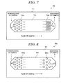
- diameters of pillars 72a, 72b formed on a first substrate 71 are the same all across an entire flow path 73, whereas spacings between the pillars 72a, 72b may be set to be different.
- the adjacent pillars 72a on an inlet side of the sample are formed to be equi-spaced apart from each other at a distance d1 while the adjacent pillars 72b on an outlet side of the sample are equi-spaced apart from each other at a distance d2 (d2 ⁇ d1).
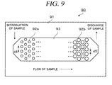
- pillars 82a and 82b having different diameters in a flow path 83 while setting the spacing between adjacent pillars 82a to be the same with the spacing between adjacent pillars 82b.
- the diameter of the pillar 82a is set to be smaller than the diameter of the pillar 82b.
- the adjacent pillars 82a are equi-spaced apart from each other at a distance d3, while the adjacent pillars 82b are equi-spaced apart from each other at the same distance d3.
- pillars 92a and 92b having different diameters in a flow path 93, and a distance between adjacent pillars 92a or the distance between adjacent pillars 82b may be changed.
- the diameter of a pillar 92a formed on an inlet side of a sample is set to be smaller than that of the pillar 92b formed on an outlet side of a sample.
- adjacent pillars 92a or adjacent pillars 92b are equi-spaced apart from each other.
- the distance d4 between the adjacent pillars 92a is formed larger than the distance d5 between the adjacent pillars 92b (d5 ⁇ d4).
- the present embodiment has been described for the configuration in which the pillars are more densely arranged on the outlet side of sample than on the inlet side of the sample.
- the spacing between the pillars, the diameter of each pillar or the like it is possible to manufacture the column having the desired level of separation efficiency depending on the property of the sample, the required level of analysis accuracy, and the like.
- the arrangement density of the pillars can be altered in multiple stages. They can be altered periodically or combined arbitrarily.
- the shape of the pillar has a circular shape when viewed from the top thereof.
- the shape of the pillar is not limited to the circular shape but it can have a semicircular shape, a rectangular shape, a polygonal shape, or the like.
- the present invention has many advantages when it is used in an apparatus for analyzing materials contained in a sample. Further, the present invention can also be employed in a manufacturing method for such apparatus.
Landscapes
- Chemical & Material Sciences (AREA)
- General Health & Medical Sciences (AREA)
- Life Sciences & Earth Sciences (AREA)
- Health & Medical Sciences (AREA)
- Analytical Chemistry (AREA)
- Biochemistry (AREA)
- Physics & Mathematics (AREA)
- General Physics & Mathematics (AREA)
- Immunology (AREA)
- Pathology (AREA)
- Engineering & Computer Science (AREA)
- Nanotechnology (AREA)
- Treatment Of Liquids With Adsorbents In General (AREA)
Priority Applications (1)
| Application Number | Priority Date | Filing Date | Title |
|---|---|---|---|
| EP12169531A EP2538212A1 (de) | 2006-08-14 | 2007-08-14 | Chromatographiesäule |
Applications Claiming Priority (2)
| Application Number | Priority Date | Filing Date | Title |
|---|---|---|---|
| JP2006220908A JP5173165B2 (ja) | 2006-08-14 | 2006-08-14 | クロマトグラフィ用のカラム及びその製造方法 |
| PCT/JP2007/065861 WO2008020593A1 (en) | 2006-08-14 | 2007-08-14 | Column for chromatography and method for producing the same |
Related Child Applications (1)
| Application Number | Title | Priority Date | Filing Date |
|---|---|---|---|
| EP12169531A Division-Into EP2538212A1 (de) | 2006-08-14 | 2007-08-14 | Chromatographiesäule |
Publications (3)
| Publication Number | Publication Date |
|---|---|
| EP2048497A1 true EP2048497A1 (de) | 2009-04-15 |
| EP2048497A4 EP2048497A4 (de) | 2010-02-24 |
| EP2048497B1 EP2048497B1 (de) | 2014-10-08 |
Family
ID=39082118
Family Applications (2)
| Application Number | Title | Priority Date | Filing Date |
|---|---|---|---|
| EP12169531A Withdrawn EP2538212A1 (de) | 2006-08-14 | 2007-08-14 | Chromatographiesäule |
| EP07792504.8A Not-in-force EP2048497B1 (de) | 2006-08-14 | 2007-08-14 | Chromatographiesäule und verfahren zur herstellung davon |
Family Applications Before (1)
| Application Number | Title | Priority Date | Filing Date |
|---|---|---|---|
| EP12169531A Withdrawn EP2538212A1 (de) | 2006-08-14 | 2007-08-14 | Chromatographiesäule |
Country Status (5)
| Country | Link |
|---|---|
| US (1) | US20100032357A1 (de) |
| EP (2) | EP2538212A1 (de) |
| JP (1) | JP5173165B2 (de) |
| TW (1) | TW200831173A (de) |
| WO (1) | WO2008020593A1 (de) |
Cited By (2)
| Publication number | Priority date | Publication date | Assignee | Title |
|---|---|---|---|---|
| WO2014013368A1 (fr) * | 2012-07-19 | 2014-01-23 | Commissariat A L'energie Atomique Et Aux Energies Alternatives | Procédé de fabrication d'une colonne d'analyse de chromatographie |
| US9885692B2 (en) | 2012-07-19 | 2018-02-06 | Commissariat A L'energie Atomique Et Aux Energies Alternatives | Method for producing a chromatography-enrichment column |
Families Citing this family (13)
| Publication number | Priority date | Publication date | Assignee | Title |
|---|---|---|---|---|
| JP5396587B2 (ja) * | 2008-03-11 | 2014-01-22 | 富山県 | ナノ柱状構造体及びその製造方法と応用デバイス |
| WO2009129850A1 (en) * | 2008-04-23 | 2009-10-29 | Agilent Technologies, Inc. | Microstructured separation element with a porous surface coating |
| JP2011174856A (ja) * | 2010-02-25 | 2011-09-08 | Tokyo Electron Ltd | クロマトグラフィー用カラム、その製造方法、および分析装置 |
| US20130206667A1 (en) * | 2010-11-16 | 2013-08-15 | Nobull Innovation Llc | Apparatus for making a chromatography column |
| WO2013039487A1 (en) * | 2011-09-13 | 2013-03-21 | Empire Technology Development Llc | Miniaturized gas chromatograph |
| EP2969154A4 (de) * | 2013-03-15 | 2017-04-19 | PECOFacet (US), Inc. | Vliesfilterelement mit modifizierter oberflächenenergie |
| US10463105B2 (en) | 2014-08-27 | 2019-11-05 | Nike, Inc. | Articles of footwear, apparel, and sports equipment with soil-shedding properties |
| US10064447B2 (en) | 2014-08-27 | 2018-09-04 | Nike, Inc. | Article of footwear with soil-shedding performance |
| TWI706737B (zh) | 2014-08-27 | 2020-10-11 | 荷蘭商耐基創新公司 | 具污垢脫落性能之鞋類製品 |
| US10531705B2 (en) | 2016-03-02 | 2020-01-14 | Nike, Inc. | Hydrogel tie layer |
| BE1025524B1 (nl) * | 2017-09-04 | 2019-04-05 | PharmaFluidics N.V. | Chemische reactoren |
| BE1027013B1 (nl) * | 2019-01-31 | 2020-09-01 | Pharmafluidics N V | Filter voor chemische reactoren |
| TWI738581B (zh) * | 2020-12-03 | 2021-09-01 | 國立臺灣師範大學 | 平板式氧化鋁氣相層析管柱及其製作方法 |
Family Cites Families (16)
| Publication number | Priority date | Publication date | Assignee | Title |
|---|---|---|---|---|
| JPH07120450A (ja) * | 1993-10-22 | 1995-05-12 | Sumika Bunseki Center:Kk | 多孔質体クロマトグラフィー用カラム |
| US6156273A (en) * | 1997-05-27 | 2000-12-05 | Purdue Research Corporation | Separation columns and methods for manufacturing the improved separation columns |
| US6368871B1 (en) * | 1997-08-13 | 2002-04-09 | Cepheid | Non-planar microstructures for manipulation of fluid samples |
| EP1003759A2 (de) * | 1997-08-13 | 2000-05-31 | Cepheid | Mikrostrukturen für die manipulation von flüssigen proben |
| AU2002251946A1 (en) * | 2001-02-14 | 2002-08-28 | Science And Technology Corporation @ Unm | Nanostructured devices for separation and analysis |
| US6752922B2 (en) * | 2001-04-06 | 2004-06-22 | Fluidigm Corporation | Microfluidic chromatography |
| JP2003222611A (ja) * | 2001-11-20 | 2003-08-08 | Nec Corp | 分離装置、分離方法および分離装置の製造方法 |
| WO2004051231A1 (ja) * | 2002-11-29 | 2004-06-17 | Nec Corporation | 分離装置および分離方法 |
| US7586091B2 (en) * | 2003-03-14 | 2009-09-08 | Nec Corporation | Mass spectrometric system and mass spectrometry |
| JP2004045410A (ja) * | 2003-08-06 | 2004-02-12 | Hitachi Ltd | 試料分離装置及び化学分析装置 |
| US20070102362A1 (en) * | 2003-09-01 | 2007-05-10 | Kazuhiro Iida | Chip |
| DE10349471B4 (de) * | 2003-10-23 | 2009-07-23 | Fraunhofer-Gesellschaft zur Förderung der angewandten Forschung e.V. | Nanoporöse Filter- oder Trägermembran sowie Verfahren zur Herstellung |
| JP4314109B2 (ja) * | 2003-12-15 | 2009-08-12 | キヤノン株式会社 | 物質分離素子及びその製造方法 |
| US20050242017A1 (en) * | 2004-04-15 | 2005-11-03 | Staats Sau Lan T | Microfluidic devices for liquid chromatography and mass spectrometry |
| WO2006097302A1 (en) * | 2005-03-17 | 2006-09-21 | Vrije Universiteit Brussel | Method for manufacturing packed bed column and packed bed column obtained therewith |
| JP5125315B2 (ja) * | 2007-08-24 | 2013-01-23 | 東京エレクトロン株式会社 | クロマト検出装置 |
-
2006
- 2006-08-14 JP JP2006220908A patent/JP5173165B2/ja not_active Expired - Fee Related
-
2007
- 2007-08-14 WO PCT/JP2007/065861 patent/WO2008020593A1/ja not_active Ceased
- 2007-08-14 EP EP12169531A patent/EP2538212A1/de not_active Withdrawn
- 2007-08-14 TW TW096130055A patent/TW200831173A/zh unknown
- 2007-08-14 US US12/377,274 patent/US20100032357A1/en not_active Abandoned
- 2007-08-14 EP EP07792504.8A patent/EP2048497B1/de not_active Not-in-force
Cited By (3)
| Publication number | Priority date | Publication date | Assignee | Title |
|---|---|---|---|---|
| WO2014013368A1 (fr) * | 2012-07-19 | 2014-01-23 | Commissariat A L'energie Atomique Et Aux Energies Alternatives | Procédé de fabrication d'une colonne d'analyse de chromatographie |
| US9835599B2 (en) | 2012-07-19 | 2017-12-05 | Commissariat A L'energie Atomique Et Aux Energies Alternatives | Method for producing a chromatography analysis column |
| US9885692B2 (en) | 2012-07-19 | 2018-02-06 | Commissariat A L'energie Atomique Et Aux Energies Alternatives | Method for producing a chromatography-enrichment column |
Also Published As
| Publication number | Publication date |
|---|---|
| JP5173165B2 (ja) | 2013-03-27 |
| EP2538212A1 (de) | 2012-12-26 |
| EP2048497A4 (de) | 2010-02-24 |
| TW200831173A (en) | 2008-08-01 |
| JP2008045966A (ja) | 2008-02-28 |
| EP2048497B1 (de) | 2014-10-08 |
| WO2008020593A1 (en) | 2008-02-21 |
| US20100032357A1 (en) | 2010-02-11 |
Similar Documents
| Publication | Publication Date | Title |
|---|---|---|
| EP2048497B1 (de) | Chromatographiesäule und verfahren zur herstellung davon | |
| US10058895B2 (en) | Continuous flow, size-based separation of entities down to the nanometer scale using nanopillar arrays | |
| US10393642B2 (en) | Pillar array structure with uniform and high aspect ratio nanometer gaps | |
| JP4074921B2 (ja) | 質量分析システムおよび分析方法 | |
| US9835539B2 (en) | Biopolymer separation using nanostructured arrays | |
| JP5904958B2 (ja) | 半導体マイクロ分析チップ及びその製造方法 | |
| JP2004045357A (ja) | 分離装置およびその製造方法 | |
| EP1545740A2 (de) | Integrierte vorrichtungen und verfahren zur behandlung von flüssigkeiten | |
| CN1162928A (zh) | 用于在不混溶流体之间进行扩散传递的方法与设备 | |
| DK2953716T3 (en) | CHEMICAL REACTOR EQUIPMENT | |
| US10507466B2 (en) | Metal assisted chemical etching for fabricating high aspect ratio and straight silicon nanopillar arrays for sorting applications | |
| JP3695431B2 (ja) | 分離装置および分離装置の製造方法 | |
| JP2003222611A (ja) | 分離装置、分離方法および分離装置の製造方法 | |
| CA2436354C (en) | Separator and method of manufacturing a separator | |
| JP2003519367A (ja) | 単分散状態の粒子を採用するキャピラリカラム | |
| KR102682799B1 (ko) | 3차원 전극 기반 미세유체 측정장치 및 그 제조방법 | |
| Romita et al. | Rapid fabrication of sieved microwells and cross-flow microparticle trapping | |
| Crane et al. | Manipulating the inter pillar gap in pillar array ultra-thin layer planar chromatography platforms | |
| CN117280207A (zh) | 柱结构 | |
| CN118028102A (zh) | 级联型分子筛选阵列的芯片、工艺和外泌体分离方法 | |
| Zhu et al. | DLD-based on-chip sample handling for label-free single-cell MS cytometry | |
| HK40040809B (en) | Microfluidic probe head with barrier projections | |
| Crowley | Blood separation with passive microfluidic devices for lab-on-a-chip applications | |
| Wang | Multi-level filter based on H shaped channels | |
| HK40040809A (en) | Microfluidic probe head with barrier projections |
Legal Events
| Date | Code | Title | Description |
|---|---|---|---|
| PUAI | Public reference made under article 153(3) epc to a published international application that has entered the european phase |
Free format text: ORIGINAL CODE: 0009012 |
|
| 17P | Request for examination filed |
Effective date: 20090213 |
|
| AK | Designated contracting states |
Kind code of ref document: A1 Designated state(s): AT BE BG CH CY CZ DE DK EE ES FI FR GB GR HU IE IS IT LI LT LU LV MC MT NL PL PT RO SE SI SK TR |
|
| AX | Request for extension of the european patent |
Extension state: AL BA HR MK RS |
|
| A4 | Supplementary search report drawn up and despatched |
Effective date: 20100121 |
|
| RIC1 | Information provided on ipc code assigned before grant |
Ipc: G01N 30/52 20060101ALI20100115BHEP Ipc: G01N 30/88 20060101ALI20100115BHEP Ipc: G01N 30/60 20060101AFI20080328BHEP |
|
| 17Q | First examination report despatched |
Effective date: 20100520 |
|
| DAX | Request for extension of the european patent (deleted) | ||
| GRAP | Despatch of communication of intention to grant a patent |
Free format text: ORIGINAL CODE: EPIDOSNIGR1 |
|
| INTG | Intention to grant announced |
Effective date: 20140327 |
|
| GRAS | Grant fee paid |
Free format text: ORIGINAL CODE: EPIDOSNIGR3 |
|
| GRAA | (expected) grant |
Free format text: ORIGINAL CODE: 0009210 |
|
| AK | Designated contracting states |
Kind code of ref document: B1 Designated state(s): AT BE BG CH CY CZ DE DK EE ES FI FR GB GR HU IE IS IT LI LT LU LV MC MT NL PL PT RO SE SI SK TR |
|
| REG | Reference to a national code |
Ref country code: GB Ref legal event code: FG4D |
|
| REG | Reference to a national code |
Ref country code: CH Ref legal event code: EP Ref country code: AT Ref legal event code: REF Ref document number: 690893 Country of ref document: AT Kind code of ref document: T Effective date: 20141015 |
|
| REG | Reference to a national code |
Ref country code: IE Ref legal event code: FG4D |
|
| REG | Reference to a national code |
Ref country code: DE Ref legal event code: R096 Ref document number: 602007038836 Country of ref document: DE Effective date: 20141120 |
|
| REG | Reference to a national code |
Ref country code: NL Ref legal event code: VDEP Effective date: 20141008 |
|
| REG | Reference to a national code |
Ref country code: AT Ref legal event code: MK05 Ref document number: 690893 Country of ref document: AT Kind code of ref document: T Effective date: 20141008 |
|
| REG | Reference to a national code |
Ref country code: LT Ref legal event code: MG4D |
|
| PG25 | Lapsed in a contracting state [announced via postgrant information from national office to epo] |
Ref country code: NL Free format text: LAPSE BECAUSE OF FAILURE TO SUBMIT A TRANSLATION OF THE DESCRIPTION OR TO PAY THE FEE WITHIN THE PRESCRIBED TIME-LIMIT Effective date: 20141008 |
|
| PG25 | Lapsed in a contracting state [announced via postgrant information from national office to epo] |
Ref country code: LT Free format text: LAPSE BECAUSE OF FAILURE TO SUBMIT A TRANSLATION OF THE DESCRIPTION OR TO PAY THE FEE WITHIN THE PRESCRIBED TIME-LIMIT Effective date: 20141008 Ref country code: FI Free format text: LAPSE BECAUSE OF FAILURE TO SUBMIT A TRANSLATION OF THE DESCRIPTION OR TO PAY THE FEE WITHIN THE PRESCRIBED TIME-LIMIT Effective date: 20141008 Ref country code: PT Free format text: LAPSE BECAUSE OF FAILURE TO SUBMIT A TRANSLATION OF THE DESCRIPTION OR TO PAY THE FEE WITHIN THE PRESCRIBED TIME-LIMIT Effective date: 20150209 Ref country code: IS Free format text: LAPSE BECAUSE OF FAILURE TO SUBMIT A TRANSLATION OF THE DESCRIPTION OR TO PAY THE FEE WITHIN THE PRESCRIBED TIME-LIMIT Effective date: 20150208 Ref country code: ES Free format text: LAPSE BECAUSE OF FAILURE TO SUBMIT A TRANSLATION OF THE DESCRIPTION OR TO PAY THE FEE WITHIN THE PRESCRIBED TIME-LIMIT Effective date: 20141008 |
|
| PG25 | Lapsed in a contracting state [announced via postgrant information from national office to epo] |
Ref country code: AT Free format text: LAPSE BECAUSE OF FAILURE TO SUBMIT A TRANSLATION OF THE DESCRIPTION OR TO PAY THE FEE WITHIN THE PRESCRIBED TIME-LIMIT Effective date: 20141008 Ref country code: SE Free format text: LAPSE BECAUSE OF FAILURE TO SUBMIT A TRANSLATION OF THE DESCRIPTION OR TO PAY THE FEE WITHIN THE PRESCRIBED TIME-LIMIT Effective date: 20141008 Ref country code: PL Free format text: LAPSE BECAUSE OF FAILURE TO SUBMIT A TRANSLATION OF THE DESCRIPTION OR TO PAY THE FEE WITHIN THE PRESCRIBED TIME-LIMIT Effective date: 20141008 Ref country code: LV Free format text: LAPSE BECAUSE OF FAILURE TO SUBMIT A TRANSLATION OF THE DESCRIPTION OR TO PAY THE FEE WITHIN THE PRESCRIBED TIME-LIMIT Effective date: 20141008 Ref country code: CY Free format text: LAPSE BECAUSE OF FAILURE TO SUBMIT A TRANSLATION OF THE DESCRIPTION OR TO PAY THE FEE WITHIN THE PRESCRIBED TIME-LIMIT Effective date: 20141008 Ref country code: GR Free format text: LAPSE BECAUSE OF FAILURE TO SUBMIT A TRANSLATION OF THE DESCRIPTION OR TO PAY THE FEE WITHIN THE PRESCRIBED TIME-LIMIT Effective date: 20150109 |
|
| REG | Reference to a national code |
Ref country code: DE Ref legal event code: R026 Ref document number: 602007038836 Country of ref document: DE |
|
| PLBI | Opposition filed |
Free format text: ORIGINAL CODE: 0009260 |
|
| PG25 | Lapsed in a contracting state [announced via postgrant information from national office to epo] |
Ref country code: EE Free format text: LAPSE BECAUSE OF FAILURE TO SUBMIT A TRANSLATION OF THE DESCRIPTION OR TO PAY THE FEE WITHIN THE PRESCRIBED TIME-LIMIT Effective date: 20141008 Ref country code: CZ Free format text: LAPSE BECAUSE OF FAILURE TO SUBMIT A TRANSLATION OF THE DESCRIPTION OR TO PAY THE FEE WITHIN THE PRESCRIBED TIME-LIMIT Effective date: 20141008 Ref country code: RO Free format text: LAPSE BECAUSE OF FAILURE TO SUBMIT A TRANSLATION OF THE DESCRIPTION OR TO PAY THE FEE WITHIN THE PRESCRIBED TIME-LIMIT Effective date: 20141008 Ref country code: SK Free format text: LAPSE BECAUSE OF FAILURE TO SUBMIT A TRANSLATION OF THE DESCRIPTION OR TO PAY THE FEE WITHIN THE PRESCRIBED TIME-LIMIT Effective date: 20141008 Ref country code: DK Free format text: LAPSE BECAUSE OF FAILURE TO SUBMIT A TRANSLATION OF THE DESCRIPTION OR TO PAY THE FEE WITHIN THE PRESCRIBED TIME-LIMIT Effective date: 20141008 |
|
| 26 | Opposition filed |
Opponent name: PHARMAFLUIDICS Effective date: 20150708 |
|
| PLAX | Notice of opposition and request to file observation + time limit sent |
Free format text: ORIGINAL CODE: EPIDOSNOBS2 |
|
| PG25 | Lapsed in a contracting state [announced via postgrant information from national office to epo] |
Ref country code: IT Free format text: LAPSE BECAUSE OF FAILURE TO SUBMIT A TRANSLATION OF THE DESCRIPTION OR TO PAY THE FEE WITHIN THE PRESCRIBED TIME-LIMIT Effective date: 20141008 |
|
| PG25 | Lapsed in a contracting state [announced via postgrant information from national office to epo] |
Ref country code: SI Free format text: LAPSE BECAUSE OF FAILURE TO SUBMIT A TRANSLATION OF THE DESCRIPTION OR TO PAY THE FEE WITHIN THE PRESCRIBED TIME-LIMIT Effective date: 20141008 |
|
| REG | Reference to a national code |
Ref country code: DE Ref legal event code: R119 Ref document number: 602007038836 Country of ref document: DE |
|
| PG25 | Lapsed in a contracting state [announced via postgrant information from national office to epo] |
Ref country code: MC Free format text: LAPSE BECAUSE OF FAILURE TO SUBMIT A TRANSLATION OF THE DESCRIPTION OR TO PAY THE FEE WITHIN THE PRESCRIBED TIME-LIMIT Effective date: 20141008 Ref country code: LU Free format text: LAPSE BECAUSE OF FAILURE TO SUBMIT A TRANSLATION OF THE DESCRIPTION OR TO PAY THE FEE WITHIN THE PRESCRIBED TIME-LIMIT Effective date: 20150814 |
|
| REG | Reference to a national code |
Ref country code: CH Ref legal event code: PL |
|
| GBPC | Gb: european patent ceased through non-payment of renewal fee |
Effective date: 20150814 |
|
| PG25 | Lapsed in a contracting state [announced via postgrant information from national office to epo] |
Ref country code: CH Free format text: LAPSE BECAUSE OF NON-PAYMENT OF DUE FEES Effective date: 20150831 Ref country code: LI Free format text: LAPSE BECAUSE OF NON-PAYMENT OF DUE FEES Effective date: 20150831 |
|
| REG | Reference to a national code |
Ref country code: IE Ref legal event code: MM4A |
|
| REG | Reference to a national code |
Ref country code: FR Ref legal event code: ST Effective date: 20160429 |
|
| PG25 | Lapsed in a contracting state [announced via postgrant information from national office to epo] |
Ref country code: GB Free format text: LAPSE BECAUSE OF NON-PAYMENT OF DUE FEES Effective date: 20150814 Ref country code: IE Free format text: LAPSE BECAUSE OF NON-PAYMENT OF DUE FEES Effective date: 20150814 Ref country code: DE Free format text: LAPSE BECAUSE OF NON-PAYMENT OF DUE FEES Effective date: 20160301 |
|
| PG25 | Lapsed in a contracting state [announced via postgrant information from national office to epo] |
Ref country code: FR Free format text: LAPSE BECAUSE OF NON-PAYMENT OF DUE FEES Effective date: 20150831 |
|
| PLBP | Opposition withdrawn |
Free format text: ORIGINAL CODE: 0009264 |
|
| PLBD | Termination of opposition procedure: decision despatched |
Free format text: ORIGINAL CODE: EPIDOSNOPC1 |
|
| REG | Reference to a national code |
Ref country code: DE Ref legal event code: R100 Ref document number: 602007038836 Country of ref document: DE |
|
| PG25 | Lapsed in a contracting state [announced via postgrant information from national office to epo] |
Ref country code: MT Free format text: LAPSE BECAUSE OF FAILURE TO SUBMIT A TRANSLATION OF THE DESCRIPTION OR TO PAY THE FEE WITHIN THE PRESCRIBED TIME-LIMIT Effective date: 20141008 |
|
| PLBM | Termination of opposition procedure: date of legal effect published |
Free format text: ORIGINAL CODE: 0009276 |
|
| STAA | Information on the status of an ep patent application or granted ep patent |
Free format text: STATUS: OPPOSITION PROCEDURE CLOSED |
|
| PG25 | Lapsed in a contracting state [announced via postgrant information from national office to epo] |
Ref country code: HU Free format text: LAPSE BECAUSE OF FAILURE TO SUBMIT A TRANSLATION OF THE DESCRIPTION OR TO PAY THE FEE WITHIN THE PRESCRIBED TIME-LIMIT; INVALID AB INITIO Effective date: 20070814 Ref country code: BG Free format text: LAPSE BECAUSE OF FAILURE TO SUBMIT A TRANSLATION OF THE DESCRIPTION OR TO PAY THE FEE WITHIN THE PRESCRIBED TIME-LIMIT Effective date: 20141008 |
|
| 27C | Opposition proceedings terminated |
Effective date: 20170212 |
|
| PG25 | Lapsed in a contracting state [announced via postgrant information from national office to epo] |
Ref country code: TR Free format text: LAPSE BECAUSE OF FAILURE TO SUBMIT A TRANSLATION OF THE DESCRIPTION OR TO PAY THE FEE WITHIN THE PRESCRIBED TIME-LIMIT Effective date: 20141008 |
|
| PG25 | Lapsed in a contracting state [announced via postgrant information from national office to epo] |
Ref country code: BE Free format text: LAPSE BECAUSE OF FAILURE TO SUBMIT A TRANSLATION OF THE DESCRIPTION OR TO PAY THE FEE WITHIN THE PRESCRIBED TIME-LIMIT Effective date: 20141008 |