EP2048681A1 - Elektrisches Steuermodul und ein solches Modul umfassende Vorrichtung - Google Patents
Elektrisches Steuermodul und ein solches Modul umfassende Vorrichtung Download PDFInfo
- Publication number
- EP2048681A1 EP2048681A1 EP08105543A EP08105543A EP2048681A1 EP 2048681 A1 EP2048681 A1 EP 2048681A1 EP 08105543 A EP08105543 A EP 08105543A EP 08105543 A EP08105543 A EP 08105543A EP 2048681 A1 EP2048681 A1 EP 2048681A1
- Authority
- EP
- European Patent Office
- Prior art keywords
- electrical
- support
- control module
- base
- switch
- Prior art date
- Legal status (The legal status is an assumption and is not a legal conclusion. Google has not performed a legal analysis and makes no representation as to the accuracy of the status listed.)
- Withdrawn
Links
- 230000008859 change Effects 0.000 claims abstract description 5
- 230000000295 complement effect Effects 0.000 claims abstract description 5
- 239000000463 material Substances 0.000 claims abstract 2
- 238000010200 validation analysis Methods 0.000 claims description 10
- 238000003825 pressing Methods 0.000 claims description 7
- 238000000034 method Methods 0.000 claims description 2
- 239000012528 membrane Substances 0.000 claims 3
- 238000004519 manufacturing process Methods 0.000 description 4
- 238000009434 installation Methods 0.000 description 2
- 230000004913 activation Effects 0.000 description 1
- 238000004026 adhesive bonding Methods 0.000 description 1
- 230000005540 biological transmission Effects 0.000 description 1
- 230000006835 compression Effects 0.000 description 1
- 238000007906 compression Methods 0.000 description 1
- 230000003993 interaction Effects 0.000 description 1
- 238000011031 large-scale manufacturing process Methods 0.000 description 1
- 230000005415 magnetization Effects 0.000 description 1
- 230000007257 malfunction Effects 0.000 description 1
- 238000009423 ventilation Methods 0.000 description 1
Images

Classifications
-
- H—ELECTRICITY
- H01—ELECTRIC ELEMENTS
- H01H—ELECTRIC SWITCHES; RELAYS; SELECTORS; EMERGENCY PROTECTIVE DEVICES
- H01H25/00—Switches with compound movement of handle or other operating part
- H01H25/008—Operating part movable both angularly and rectilinearly, the rectilinear movement being perpendicular to the axis of angular movement
-
- H—ELECTRICITY
- H01—ELECTRIC ELEMENTS
- H01H—ELECTRIC SWITCHES; RELAYS; SELECTORS; EMERGENCY PROTECTIVE DEVICES
- H01H1/00—Contacts
- H01H1/58—Electric connections to or between contacts; Terminals
- H01H1/5805—Connections to printed circuits
-
- H—ELECTRICITY
- H01—ELECTRIC ELEMENTS
- H01H—ELECTRIC SWITCHES; RELAYS; SELECTORS; EMERGENCY PROTECTIVE DEVICES
- H01H19/00—Switches operated by an operating part which is rotatable about a longitudinal axis thereof and which is acted upon directly by a solid body external to the switch, e.g. by a hand
- H01H19/02—Details
- H01H19/10—Movable parts; Contacts mounted thereon
- H01H19/14—Operating parts, e.g. turn knob
- H01H2019/146—Roller type actuators
Definitions
- the present invention relates to an electrical control module.
- This electrical control module can be used to navigate in a menu to select and then validate an order and finds a particular application, particularly in the automotive sector, without however that it is limiting. It can be used as steering wheel controls to control the operation of the various electrical and electronic components of the vehicle (lights, mirrors, telephone, radio or a multimedia device for example).
- the indexing unit comprises a rotor and a stator having magnetic angular sectors whose interaction makes it possible to define stable and unstable angular positions thus creating the indexing.
- This device does not include a switch and therefore does not allow the validation of a rotary control.
- the object of the invention is therefore to solve the aforementioned drawbacks of the state of the art and to provide a control module enabling validation and whose electrical connections are improved in order to increase the reliability and the service life and to facilitate the installation of the control device.
- the invention also aims to allow a simplified assembly of the various elements to reduce production costs.
- the invention relates to an electrical control module comprising a support intended to be pivotally mounted on a base, a rotary electrical control member mounted on said support and at least one electrical switch for validation by pressing on the rotary member. , characterized in that it comprises first electrical connection means carried by the support and intended to cooperate with second complementary connecting means carried by the base, the first and second electrical connection means being formed by flexible blades and electrical tracks or vice versa and in that the switch is carried by a face of the pivoting support intended to be opposite the base so that a pivoting movement of the support causes a change of state of the switch in order to a validation of an order.
- the present invention can be used, inter alia, in a vehicle, as steering wheel control or dashboard control to control the various items of equipment such as radio, ventilation or mirrors.
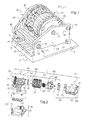
- the control device represented on the figure 1 , comprises a control module 1 pivotally mounted on a base 3.
- This base 3 is intended to be fixed, for example, on a branch of a car steering wheel.
- this base 3 comprises a base 5 carrying a rectangular plate 7.
- the latter has four parallel electrical tracks 9.
- the tracks 9 are intended to be connected to a microprocessor (not shown) to manage and transmit to the various elements of electrical signals from the control module 1.
- Said plate 7 is fixed to the base 5 for example by two screws 11. An attachment by gluing or snapping can also be provided.
- the base 5 is surmounted on one side by two parallel flanges 13 each having a semicircular notch 15 in order to pivotably support the module 1.
- the base 5 is surmounted by a fastener 17 for holding the module 1 in a stable rest position.
- the control module 1 comprises a support 19 carrying on the one hand a rotary control member 21 and on the other hand a switch 23.
- the support 19 is made in two parts 25 and 27 assembled to one another by snapping.
- the part 25 of the support 19 comprises a lateral face 29 which supports, at one of its ends, a longitudinal side in the form of spar 31.
- the latter is perpendicular to the lateral face 29 and has an axis 33 projecting at both ends of the spar 31 so as to pivot the control module 1 on the base 3.
- the spar 31 also has a groove 35 in its length to allow the latching of the two parts 25 and 27 of the support.
- the side face 29 has, at its other end, two holes 37 and 39 intended to provide the connection between the two parts 25 and 27 of the support 19 and whose roles will be specified in the following description.
- the portion 27 of the support 19 has a lateral face 41 and a longitudinal side, constituting the rear wall 43, perpendicularly connected to one another at their ends. At its other end, the lateral face 41 supports a rod 45 which extends parallel to the rear wall 43 and ends with a hook 47. The latter is snapped into the groove 35 during assembly. The lateral face 41 is also pierced, near the rod 45, with a hole 49 allowing the end of the spar 31 to fit together.
- the rear wall 43 carries, in its outer extension, another hook 51 and a pin 53. The latter is inserted into the hole 37 of the element 25 described above. The hook 51 comes to him, snap into the hole 39 during assembly.
- the rear wall 43 has a base 55 to which are fixed four flexible electric blades 57 which extend parallel to the lateral face 41 of the portion 27 so as to come into contact with the electrical tracks 9 of the base 3, once the assembly completed.
- the switch 23 is also fixed to said base 55 so as to face the base 3 once the elements are assembled, as shown in FIG. figure 4 .
- the rear wall 43 further comprises an appendix 59 on its outer face which is positioned in the fastener 17 of the base 3.
- the side faces 29 and 41 are respectively pierced with holes 61 and 63, the latter are aligned, once the parts 25 and 27 snapped, in order to accommodate the rotary control member 21.
- An electrical circuit 65 integrated by an overmolding technique extends in a circular manner on the inside of the lateral face 41 of the part 27 of the support 19 and connects the flexible electrical blades 57 of the rear wall 43.
- the electric tracks of the blades For two of them, the hoses 57 correspond to the electrical signal coming from the rotary member 21, the third to the signal from the switch and the last to the electrical ground.
- the electrical part of the support 19 of the control module 1 is carried by the portion 27, the portion 25 being only mechanical.
- the electrical circuit 65 is controlled using the rotary member 21 carried by the support 19.
- the control member 21 is made of several parts assembled to perform the electrical functions of control, manipulation and indexing, this last being preferably magnetic.
- the manipulation function is achieved by means of a cylindrical sleeve 67 whose outer periphery is fluted to facilitate the application of a rotary control, by example by a user's finger.
- This sleeve 67 has at its end 68 in front of the circuit 65 an annular wall portion carrying a scraper 81 with three branches intended to be in contact with the circuit 65 to obtain an electrical signal representative of the rotational position of the sleeve 67
- Each branch is made by a pair of fins 83 to obtain a double contact to reduce the risk of malfunction.
- the sleeve 67 is rotated by the drum 69 with a through axis 71, one end of which is housed in the hole 63 and the other end of which is housed in the hole 61.
- grooves 85 On the periphery of the drum are provided grooves 85 shifted at 120 ° which cooperate with complementary ribs (not visible in the figures) on the inner cylindrical wall of the sleeve 67.
- the rotational movement of the sleeve is indexed by an indexing unit magnetic rotor 75 formed by a rotor 77 carried by the drum 69 and a stator 79 carried by the side face 29.
- the rotor 77 and stator 79 are disks having magnetic sectors alternating pole "north" and "south” pole. Alternatively, one of the polarities (“north" or "south”) can also be replaced by non-magnetic sectors.
- the fixing of the rotor 77 on the drum 69 on the one hand and the stator 79 on the lateral face 29 on the other hand is achieved by a fixing with tenons and complementary notches.
- the drum 69 carries on its axis 71 on the opposite side to the indexing unit 75 a helical spring 73 intended to hold the various elements of the rotary control member 21 in position by pressing on one side on the face side 41 and the other side against the drum 69.
- stator 79 and the rotor 77 fit respectively on the lateral face 29 and on one side of the drum 69. On the other side of the latter are snapped on the one hand the spring 73 around of the axis 71 and secondly the sleeve 67 on the outer diameter.
- the two parts 29 and 41 of the support 19 are positioned on either side of the rotary member 21. Their bringing together, until their snap-in, is accompanied by the introduction of the ends of the axis 71 into the holes 61 and 63, the contacting of the wiper 81 with the electrical circuit 65 and the proximity of the rotor 77 and the stator 79.
- the axis 33 of the module 1 can be inserted into the notches 15 of the base 5.
- the appendix 59 can then snap into the fastener 17 of the base 5, causing the flexible blades 57 to come into contact with the electrical tracks 9.
- the rotary member 21 can rotate about the axis 71, itself carried by the support 19.
- the latter can rotate about its axis 33, itself supported by the notches 15. Nevertheless, the pivoting is blocked in one direction by the fastener 17 and in the other by the base 5 via the switch 23.
- the device according to the invention is distinguished by its simplicity of assembly and the fact that the control module carries the entire electrical switching circuit.
- the user rotates the rotary control member 21 by applying a force tangential to the rotary control member 21.
- the magnet sectors of the rotor 77 then transiently pass into a position where they are facing magnetic sectors of the stator 79 of the same polarity.
- the magnetic fields repel and cause a slight shift of the rotor 77 along the axis 71 and the compression of the spring 73.
- This position is unstable.
- the user feels a resistance and the passage of a hard point.
- the operator continues the rotational movement of the member 21, the following stable position is reached corresponding to magnetized sectors of the rotor 77 facing areas of opposite magnetization of the stator 79.
- the return to a stable position is facilitated by the return force of the spring 73.
- the signal corresponding to the change of the positions of the contact points of the wiper 81 on the electrical circuit 65 is delivered by the latter via the flexible blades 57 to the microprocessor (not shown).
- the operator presses on the rotary member 21.
- the force applied is transmitted to the support 19, which causes it to pivot about the axis 33 and the closing of the switch 23, causing the transmission of a validation signal via the flexible blades 57.
- the two signals coming from the rotary control member 21 are, for example, two square wave signals, one being out of phase by one third of a period with respect to the other.
- the microcontroller can thus by analyzing the two received signals deduce the direction and amplitude of the rotation.
- the present invention can be applied, for example, to a speed regulator of a vehicle.
- the speed reference can be incremented or decremented by means of the rotary control member 21 until the desired desired value is reached.
- the validation by pressing on the rotary control member 21 allows the activation of the controller and causes the control of the speed of the vehicle to the preselected set value.
- Another possible application is the use of a drop-down menu on a screen.
- the rotary control member 21 makes it possible to navigate through the different items of the drop-down menu.
- the validation by pressing on the rotary control member 21 activates the selected item.
- the present invention is very advantageous because of its compact form facilitating its installation and its reliability, especially at its electrical contacts, ensuring optimal operation and life.
- the invention allows assembly and simplified assembly which facilitates the production in large numbers.
Landscapes
- Switches With Compound Operations (AREA)
Applications Claiming Priority (1)
| Application Number | Priority Date | Filing Date | Title |
|---|---|---|---|
| FR0707119A FR2922332B1 (fr) | 2007-10-10 | 2007-10-10 | Module de commande electrique et dispositif comportant un tel module |
Publications (1)
| Publication Number | Publication Date |
|---|---|
| EP2048681A1 true EP2048681A1 (de) | 2009-04-15 |
Family
ID=39283938
Family Applications (1)
| Application Number | Title | Priority Date | Filing Date |
|---|---|---|---|
| EP08105543A Withdrawn EP2048681A1 (de) | 2007-10-10 | 2008-10-10 | Elektrisches Steuermodul und ein solches Modul umfassende Vorrichtung |
Country Status (2)
| Country | Link |
|---|---|
| EP (1) | EP2048681A1 (de) |
| FR (1) | FR2922332B1 (de) |
Cited By (2)
| Publication number | Priority date | Publication date | Assignee | Title |
|---|---|---|---|---|
| FR2973932A1 (fr) * | 2011-04-06 | 2012-10-12 | Peugeot Citroen Automobiles Sa | Dispositif de commutation a double element d'actionnement rotatif pour volant de vehicule et volant comprenant un tel dispositif de commutation |
| DE102023129723A1 (de) | 2023-10-27 | 2025-04-30 | Preh Gmbh | Bedienelement mit einem verbessert drehbeweglich gelagerten, als Daumenrad ausgelegten Betätigungsteil und magnetisch zusammenwirkender Rasteinrichtung, zugehörige Verwendung sowie zugehöriges Montageverfahren |
Citations (7)
| Publication number | Priority date | Publication date | Assignee | Title |
|---|---|---|---|---|
| EP1028446A2 (de) | 1999-02-10 | 2000-08-16 | Matsushita Electric Industrial Co., Ltd. | Kombinierter Druckknopf- und Drehschalter |
| EP1094483A2 (de) * | 1999-10-19 | 2001-04-25 | Alps Electric Co., Ltd. | Kombinierte elektronische Kontroll Komponente |
| EP1387378A1 (de) * | 1998-12-25 | 2004-02-04 | Matsushita Electric Industrial Co., Ltd. | Elektronische Dreh-Druckschalterkomponente und elektronisches Gerät zu seiner Verwendung |
| EP1677326A1 (de) * | 2003-10-20 | 2006-07-05 | Omron Corporation | Elektronische komponente des dreh- und druckbetriebstyps und elektronische einrichtung damit |
| US20060192764A1 (en) * | 2005-02-28 | 2006-08-31 | Microsoft Corporation | Navigation wheel having switching assembly |
| US20060207451A1 (en) * | 2005-03-18 | 2006-09-21 | Speed Tech Corp. | Mobile navigator having locked braces |
| FR2888648A1 (fr) | 2005-07-18 | 2007-01-19 | Sc2N Sa | Unite d'indexage et un dispositif de commande comprenant une telle unite d'indexage |
-
2007
- 2007-10-10 FR FR0707119A patent/FR2922332B1/fr active Active
-
2008
- 2008-10-10 EP EP08105543A patent/EP2048681A1/de not_active Withdrawn
Patent Citations (7)
| Publication number | Priority date | Publication date | Assignee | Title |
|---|---|---|---|---|
| EP1387378A1 (de) * | 1998-12-25 | 2004-02-04 | Matsushita Electric Industrial Co., Ltd. | Elektronische Dreh-Druckschalterkomponente und elektronisches Gerät zu seiner Verwendung |
| EP1028446A2 (de) | 1999-02-10 | 2000-08-16 | Matsushita Electric Industrial Co., Ltd. | Kombinierter Druckknopf- und Drehschalter |
| EP1094483A2 (de) * | 1999-10-19 | 2001-04-25 | Alps Electric Co., Ltd. | Kombinierte elektronische Kontroll Komponente |
| EP1677326A1 (de) * | 2003-10-20 | 2006-07-05 | Omron Corporation | Elektronische komponente des dreh- und druckbetriebstyps und elektronische einrichtung damit |
| US20060192764A1 (en) * | 2005-02-28 | 2006-08-31 | Microsoft Corporation | Navigation wheel having switching assembly |
| US20060207451A1 (en) * | 2005-03-18 | 2006-09-21 | Speed Tech Corp. | Mobile navigator having locked braces |
| FR2888648A1 (fr) | 2005-07-18 | 2007-01-19 | Sc2N Sa | Unite d'indexage et un dispositif de commande comprenant une telle unite d'indexage |
Cited By (2)
| Publication number | Priority date | Publication date | Assignee | Title |
|---|---|---|---|---|
| FR2973932A1 (fr) * | 2011-04-06 | 2012-10-12 | Peugeot Citroen Automobiles Sa | Dispositif de commutation a double element d'actionnement rotatif pour volant de vehicule et volant comprenant un tel dispositif de commutation |
| DE102023129723A1 (de) | 2023-10-27 | 2025-04-30 | Preh Gmbh | Bedienelement mit einem verbessert drehbeweglich gelagerten, als Daumenrad ausgelegten Betätigungsteil und magnetisch zusammenwirkender Rasteinrichtung, zugehörige Verwendung sowie zugehöriges Montageverfahren |
Also Published As
| Publication number | Publication date |
|---|---|
| FR2922332A1 (fr) | 2009-04-17 |
| FR2922332B1 (fr) | 2009-12-18 |
Similar Documents
| Publication | Publication Date | Title |
|---|---|---|
| EP1437260B1 (de) | Auf zwei Achsen rotierbarer Fahrzeugaussenrückspiegel | |
| CA2807067C (fr) | Dispositif de detection et de signalement du changement d'etat d'un bouton-poussoir | |
| EP4154089A1 (de) | Steuerschnittstelle mit haptischem feedback | |
| EP3013649B1 (de) | Drehverbinder für eine kraftfahrzeuglenksäule | |
| FR3010546A1 (fr) | Interface de commande a retour haptique | |
| EP2072959B1 (de) | Apparat mit kontaktlosen Regelungsmitteln | |
| EP2048681A1 (de) | Elektrisches Steuermodul und ein solches Modul umfassende Vorrichtung | |
| FR2796755A1 (fr) | Commutateur electrique a organe unique d'actionnement rotatif et axial | |
| WO2013083841A1 (fr) | Dispositif de commande electrique rotatif | |
| EP1907914B1 (de) | Indizierungseinheit und steuereinrichtung mit einer solchen indizierungseinheit | |
| EP1925008B1 (de) | Einrichtung zum umschalten eines elektrischen schaltkreises unter verwendung von mindestens zwei permanentmagneten | |
| FR2509517A1 (fr) | Dispositif de commutation a depassement comportant un mecanisme de transmission a came et a lame pivotante | |
| FR2846468A1 (fr) | Organe de commande a bouton de manipulation rotatif autour de plusieurs axes | |
| EP0875912B1 (de) | Betätigungsvorrichtung mit Drehscheibe | |
| FR2496022A1 (fr) | Dispositif de commande pour avertisseurs optiques et sonores | |
| FR2812446A1 (fr) | Interrupteur non reversible de retour a la position de repos d'un moteur d'essuie-glace | |
| FR2615321A1 (fr) | Manette pour commutateur electrique | |
| WO2002099825A1 (fr) | Dispositif de commande pour vehicule automobile destine notamment a piloter un ordinateur de bord | |
| FR2571176A1 (fr) | Interrupteur de commande temporisee d'un balai mobile notamment d'un balai d'essuie-glace d'un vehicule automobile | |
| EP0048208A1 (de) | Elektrischer Impulsgenerator, insbesondere für numerische Anzeigen | |
| FR2812255A1 (fr) | Dispositif de commande d'un frein de stationnement electrique d'un vehicule automobile | |
| EP1557645B1 (de) | Relative Drehkodiereinrichtung und Armaturenbrett ausgestattet mit einer solchen Einrichtung | |
| FR2469745A1 (fr) | Dispositif de positionnement angulaire d'un arbre et son utilisation pour la commande de l'orientation d'un projecteur de vehicules automobiles | |
| FR3155078A1 (fr) | Périphérique haptique motorisée | |
| FR2571175A1 (fr) | Mecanisme de contact pour un interrupteur, notamment pour les interrupteurs de lave-glace/balai d'essuie-glace de vehicules automobiles |
Legal Events
| Date | Code | Title | Description |
|---|---|---|---|
| PUAI | Public reference made under article 153(3) epc to a published international application that has entered the european phase |
Free format text: ORIGINAL CODE: 0009012 |
|
| AK | Designated contracting states |
Kind code of ref document: A1 Designated state(s): AT BE BG CH CY CZ DE DK EE ES FI FR GB GR HR HU IE IS IT LI LT LU LV MC MT NL NO PL PT RO SE SI SK TR |
|
| AX | Request for extension of the european patent |
Extension state: AL BA MK RS |
|
| 17P | Request for examination filed |
Effective date: 20091014 |
|
| 17Q | First examination report despatched |
Effective date: 20091124 |
|
| AKX | Designation fees paid |
Designated state(s): AT BE BG CH CY CZ DE DK EE ES FI FR GB GR HR HU IE IS IT LI LT LU LV MC MT NL NO PL PT RO SE SI SK TR |
|
| GRAP | Despatch of communication of intention to grant a patent |
Free format text: ORIGINAL CODE: EPIDOSNIGR1 |
|
| GRAC | Information related to communication of intention to grant a patent modified |
Free format text: ORIGINAL CODE: EPIDOSCIGR1 |
|
| STAA | Information on the status of an ep patent application or granted ep patent |
Free format text: STATUS: THE APPLICATION IS DEEMED TO BE WITHDRAWN |
|
| 18D | Application deemed to be withdrawn |
Effective date: 20110826 |