EP2048730A1 - Membranelektrodenbaugruppe, verfahren zu ihrer herstellung und festpolymer-brennstoffzelle damit - Google Patents
Membranelektrodenbaugruppe, verfahren zu ihrer herstellung und festpolymer-brennstoffzelle damit Download PDFInfo
- Publication number
- EP2048730A1 EP2048730A1 EP07792234A EP07792234A EP2048730A1 EP 2048730 A1 EP2048730 A1 EP 2048730A1 EP 07792234 A EP07792234 A EP 07792234A EP 07792234 A EP07792234 A EP 07792234A EP 2048730 A1 EP2048730 A1 EP 2048730A1
- Authority
- EP
- European Patent Office
- Prior art keywords
- membrane
- electrolyte membrane
- electrode
- gas diffusion
- outer periphery
- Prior art date
- Legal status (The legal status is an assumption and is not a legal conclusion. Google has not performed a legal analysis and makes no representation as to the accuracy of the status listed.)
- Granted
Links
Images


Classifications
-
- H—ELECTRICITY
- H01—ELECTRIC ELEMENTS
- H01M—PROCESSES OR MEANS, e.g. BATTERIES, FOR THE DIRECT CONVERSION OF CHEMICAL ENERGY INTO ELECTRICAL ENERGY
- H01M8/00—Fuel cells; Manufacture thereof
- H01M8/02—Details
- H01M8/0271—Sealing or supporting means around electrodes, matrices or membranes
- H01M8/0273—Sealing or supporting means around electrodes, matrices or membranes with sealing or supporting means in the form of a frame
-
- H—ELECTRICITY
- H01—ELECTRIC ELEMENTS
- H01M—PROCESSES OR MEANS, e.g. BATTERIES, FOR THE DIRECT CONVERSION OF CHEMICAL ENERGY INTO ELECTRICAL ENERGY
- H01M4/00—Electrodes
- H01M4/86—Inert electrodes with catalytic activity, e.g. for fuel cells
-
- H—ELECTRICITY
- H01—ELECTRIC ELEMENTS
- H01M—PROCESSES OR MEANS, e.g. BATTERIES, FOR THE DIRECT CONVERSION OF CHEMICAL ENERGY INTO ELECTRICAL ENERGY
- H01M4/00—Electrodes
- H01M4/86—Inert electrodes with catalytic activity, e.g. for fuel cells
- H01M4/88—Processes of manufacture
-
- H—ELECTRICITY
- H01—ELECTRIC ELEMENTS
- H01M—PROCESSES OR MEANS, e.g. BATTERIES, FOR THE DIRECT CONVERSION OF CHEMICAL ENERGY INTO ELECTRICAL ENERGY
- H01M8/00—Fuel cells; Manufacture thereof
- H01M8/02—Details
- H01M8/0271—Sealing or supporting means around electrodes, matrices or membranes
- H01M8/0286—Processes for forming seals
-
- H—ELECTRICITY
- H01—ELECTRIC ELEMENTS
- H01M—PROCESSES OR MEANS, e.g. BATTERIES, FOR THE DIRECT CONVERSION OF CHEMICAL ENERGY INTO ELECTRICAL ENERGY
- H01M8/00—Fuel cells; Manufacture thereof
- H01M8/10—Fuel cells with solid electrolytes
-
- H—ELECTRICITY
- H01—ELECTRIC ELEMENTS
- H01M—PROCESSES OR MEANS, e.g. BATTERIES, FOR THE DIRECT CONVERSION OF CHEMICAL ENERGY INTO ELECTRICAL ENERGY
- H01M8/00—Fuel cells; Manufacture thereof
- H01M8/10—Fuel cells with solid electrolytes
- H01M8/1004—Fuel cells with solid electrolytes characterised by membrane-electrode assemblies [MEA]
-
- H—ELECTRICITY
- H01—ELECTRIC ELEMENTS
- H01M—PROCESSES OR MEANS, e.g. BATTERIES, FOR THE DIRECT CONVERSION OF CHEMICAL ENERGY INTO ELECTRICAL ENERGY
- H01M8/00—Fuel cells; Manufacture thereof
- H01M8/10—Fuel cells with solid electrolytes
- H01M2008/1095—Fuel cells with polymeric electrolytes
-
- Y—GENERAL TAGGING OF NEW TECHNOLOGICAL DEVELOPMENTS; GENERAL TAGGING OF CROSS-SECTIONAL TECHNOLOGIES SPANNING OVER SEVERAL SECTIONS OF THE IPC; TECHNICAL SUBJECTS COVERED BY FORMER USPC CROSS-REFERENCE ART COLLECTIONS [XRACs] AND DIGESTS
- Y02—TECHNOLOGIES OR APPLICATIONS FOR MITIGATION OR ADAPTATION AGAINST CLIMATE CHANGE
- Y02E—REDUCTION OF GREENHOUSE GAS [GHG] EMISSIONS, RELATED TO ENERGY GENERATION, TRANSMISSION OR DISTRIBUTION
- Y02E60/00—Enabling technologies; Technologies with a potential or indirect contribution to GHG emissions mitigation
- Y02E60/30—Hydrogen technology
- Y02E60/50—Fuel cells
-
- Y—GENERAL TAGGING OF NEW TECHNOLOGICAL DEVELOPMENTS; GENERAL TAGGING OF CROSS-SECTIONAL TECHNOLOGIES SPANNING OVER SEVERAL SECTIONS OF THE IPC; TECHNICAL SUBJECTS COVERED BY FORMER USPC CROSS-REFERENCE ART COLLECTIONS [XRACs] AND DIGESTS
- Y02—TECHNOLOGIES OR APPLICATIONS FOR MITIGATION OR ADAPTATION AGAINST CLIMATE CHANGE
- Y02P—CLIMATE CHANGE MITIGATION TECHNOLOGIES IN THE PRODUCTION OR PROCESSING OF GOODS
- Y02P70/00—Climate change mitigation technologies in the production process for final industrial or consumer products
- Y02P70/50—Manufacturing or production processes characterised by the final manufactured product
Definitions
- the present invention relates to a membrane electrode assembly for use in a solid polymer electrolyte fuel cell.
- Fuel cells have been attracting attention as high-efficiency energy conversion devices. Fuel cells are roughly classified, based on the type of the electrolyte used, into low-temperature operating fuel cells such as alkaline fuel cells, solid polymer electrolyte fuel cells, and phosphoric acid fuel cells, and high-temperature operating fuel cells such as molten carbonate fuel cells and solid oxide fuel cells.
- low-temperature operating fuel cells such as alkaline fuel cells, solid polymer electrolyte fuel cells, and phosphoric acid fuel cells
- high-temperature operating fuel cells such as molten carbonate fuel cells and solid oxide fuel cells.
- the solid polymer electrolyte fuel cell that uses an ionically conductive polymer electrolyte membrane as an electrolyte has been receiving attention as a power source for stationary use, automotive use, portable use, etc., because it is compact in construction, achieves high output density, does not use a liquid for the electrolyte, can operate at low temperatures, and can therefore be implemented in a simple system.
- PEFC solid polymer electrolyte fuel cell
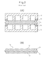
- FIG. 1 is an exploded perspective view showing the structure of a conventional fuel cell
- Figure 2 is a cross-sectional side view of its assembly.
- reactant gases introduced through a gas flow passage formed in a separator pass through the polymer electrolyte membrane and cause electrochemical reactions to occur on porous catalytic electrodes, and the power generated here is recovered outside through the separator.
- a structure constructed by placing the porous catalytic electrodes on both sides of the polymer electrolyte membrane and forming them into an integral structure by thermal pressing or the like is generally called a membrane electrode assembly (MEA).
- MEA membrane electrode assembly
- Each MEA can be handled independently, and a gasket is placed between the MEA and the separator to prevent reactant gases from leaking outside.
- the polymer electrolyte membrane has ionic conductivity, and has the function of physically and electronically isolating the fuel electrode from the oxygen electrode because of its lack of air permeability and electron conductivity.
- the area size of the polymer electrolyte membrane must be made the same as or larger than that of each porous catalytic electrode.
- the polymer electrolyte membrane is formed extending beyond the edges of the porous catalytic electrodes, and a gas sealing and supporting structure is formed by sandwiching it between the gasket and the separator.
- the polymer electrolyte membrane is formed from an extremely thin film material, the membrane is difficult to handle, and its peripheral edge which is important for reactant gas sealing may often become wrinkled, for example, when joining it to the electrodes or when assembling a plurality of unit cells to fabricate a cell stack.
- a unit cell or a cell stack fabricated using such a wrinkled polymer electrolyte membrane there is a high probability that reactant gases will leak out through the wrinkled portions. Even if the polymer electrolyte membrane is free from such wrinkles, the polymer electrolyte membrane is prone to damage as it is a component element having the least mechanical strength of all the component elements forming the stack.
- thermoplastic polymer by such means as injection molding or compression molding to the edge of an MEA having a polymer electrolyte membrane of the same size as or larger than the gas diffusion electrodes, wherein the thermoplastic polymer is impregnated into the sealing edges of the gas diffusion backings, and the seal envelops a peripheral region of both gas diffusion backings and the polymer electrolyte membrane
- thermoplastic polymer is applied by injection molding to the edge of the MEA that has a polymer electrolyte membrane larger than the gas diffusion electrodes
- the electrolyte membrane extending beyond the edge of the gas diffusion electrodes may move due to the resin flow during the injection molding and be exposed on the surface, or a load may be applied to the electrolyte membrane portion at the edge of the gas diffusion electrodes, resulting in breakage, and for these reasons, gas leakage may occur.
- Tokuhyou published Japanese Translation of PCT Application
- thermoplastic polymer is applied by injection molding to the edge of the MEA that has a polymer electrolyte membrane of the same size as the gas diffusion electrodes, the above problem does not occur, but since it is difficult to sufficiently impregnate the thermoplastic polymer into the gas diffusion electrodes, the joining between the thermoplastic polymer seal and the gas diffusion electrodes may become insufficient. Furthermore, since it is also difficult to accomplish reliable joining between the electrolyte membrane and the thermoplastic polymer seal, problems such as electrical short-circuiting between the electrodes, gas leakage through the joining portions, cell breakage, etc., can occur.
- the reliability, mechanical strength, and handling characteristics of the seal in the solid polymer electrolyte fuel cell are enhanced. Because of the enhanced mechanical strength and handling characteristics, a fuel cell stack can be assembled with good accuracy and in a simple manner. Further, according to the present invention, the manufacturing cost of the solid polymer electrolyte fuel cell is reduced by reducing the required area size of the electrolyte membrane. Furthermore, according to the present invention, the production efficiency of the solid polymer electrolyte fuel cell is enhanced by reducing the number of fabrication steps.
- a membrane electrode assembly 100 for use in a solid polymer electrolyte fuel cell according to the present invention comprises: a membrane-electrode structure which includes a polymer electrolyte membrane 130, a first electrode layer 120 provided on one side of the electrolyte membrane, a first gas diffusion layer 110 provided on an opposite side of the first electrode layer from the electrolyte membrane, a second electrode layer 140 provided on the other side of the electrolyte membrane, and a second gas diffusion layer 150 provided on an opposite side of the second electrode layer from the electrolyte membrane; and a resin frame 160 which is provided in such a manner as to fully enclose the outer periphery of the electrolyte membrane and to enclose at least portions of the outer peripheries of the first and second gas diffusion layers, the resin frame being provided so as to enclose the electrolyte membrane side.
- the first gas diffusion layer 110 and the first electrode layer 120 are stacked on a surface of the electrolyte membrane so that the outer periphery of the first gas diffusion layer 110 entirely lies within a boundary defined by the outer periphery of the electrolyte membrane 130 and so that a surface region of the electrolyte membrane 130 is left exposed between the outer periphery of the first electrode layer 120 and the outer periphery of the electrolyte membrane 130, all around the outer periphery of the first electrode layer 120.
- the second gas diffusion layer 150 extends as far as at least a portion on a side opposite from the surface region, all around the outer periphery of the electrolyte membrane 130, and the resin frame 160 is attached fixedly to at least a portion of the surface region.
- the electrolyte membrane is backed with the gas diffusion layer to provide a smooth surface having a certain degree of strength, and as a result, the electrolyte membrane does not buckle even when the resin frame is applied by die molding such as injection molding. Furthermore, since the resin frame 160 is attached fixedly to the surface region of the polymer electrolyte membrane 130, problems such as electrical short-circuiting between the first and second electrode layers, gas leakage through the joining portions, cell breakage, etc. can be resolved reliably.
- the thickness of the resin frame 160 is smaller than the thickness of the membrane-electrode structure (110 + 120 + 130 + 140 + 150), but the resin frame 160 may be made to have a thickness substantially equal to or greater than that of the membrane-electrode structure.
- FIGS 4A to 4E show modified modes of the membrane electrode assembly 100 shown in Figure 3 .
- the membrane electrode assembly 100 shown in Figure 4A is essentially the same as the membrane electrode assembly 100 shown in Figure 3 , except that the outer periphery of the first gas diffusion layer 110 entirely lies within a boundary defined by the outer periphery of the first electrode layer 120.
- the membrane electrode assembly 100 shown in Figure 4B is essentially the same as the membrane electrode assembly 100 shown in Figure 3 , except that the outer periphery of the first electrode layer 120 entirely lies within a boundary defined by the outer periphery of the first gas diffusion layer 110.
- the membrane electrode assembly 100 shown in Figure 4C is essentially the same as the membrane electrode assembly 100 shown in Figure 3 , except that the outer periphery of the second electrode layer 140 entirely lies within a boundary defined by the outer peripheries of the polymer electrolyte membrane 130 and the second gas diffusion layer 150.
- the membrane electrode assembly 100 shown in Figure 4D is essentially the same as the membrane electrode assembly 100 shown in Figure 3 , except that the outer peripheries of the polymer electrolyte membrane 130 and the second electrode layer 140 entirely lie within a boundary defined by the outer periphery of the second gas diffusion layer 150.
- the membrane electrode assembly 100 shown in Figure 4E is essentially the same as the membrane electrode assembly 100 shown in Figure 3 , except that the outer periphery of the polymer electrolyte membrane 130 entirely lies within a boundary defined by the outer periphery of the second electrode layer 140.
- the first electrode layer 120 is formed on the surface of the electrolyte membrane so that the surface region of the electrolyte membrane 130 is left exposed between the outer periphery of the first electrode layer 120 and the outer periphery of the electrolyte membrane 130, all around the outer periphery of the first electrode layer 120, as in the mode shown in Figure 3 .
- the electrolyte membrane 130 is backed with the gas diffusion layer 150 to provide a smooth surface having a certain degree of strength, and as a result, the electrolyte membrane does not buckle even when the resin frame is applied by die molding such as injection molding. Furthermore, since the resin frame 160 is attached fixedly to the surface region of the polymer electrolyte membrane 130, problems such as electrical short-circuiting between the first and second electrode layers, gas leakage through the joining portions, cell breakage, etc. can be resolved reliably.
- the thickness of the resin frame 160 is smaller than the thickness of the membrane-electrode structure (110 + 120 + 130 + 140 + 150), but the resin frame 160 may be made to have a thickness substantially equal to or greater than that of the membrane-electrode structure.
- FIG. 5 shows another modified mode of the membrane, electrode assembly 100 shown in Figure 3 .
- the membrane electrode assembly 100 shown in Figure 5 is essentially the same as the membrane electrode assembly 100 shown in Figure 3 , except that the polymer electrolyte membrane 130 is formed from two layers, the outer periphery of one electrolyte membrane entirely lying within a boundary defined by the outer periphery of the other.
- the electrolyte membrane does not buckle even when the resin frame is applied by die molding such as injection molding, and problems such as electrical short-circuiting between the first and second electrode layers, gas leakage through the joining portions, cell breakage, etc., can be resolved reliably, as in the example shown in Figure 3 ; besides, the mode shown in Figure 5 provides the additional benefit of increasing the production efficiency of the membrane electrode assembly 100, as will be described later with reference to Figure 7 .
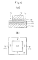
- Figure 6 shows a cross-sectional side view (A) and a top plan view (B) of the membrane-electrode structure prior to the application of the resin frame 160 in the membrane electrode assembly 100 shown in Figure 3 .
- I R indicates one example of a resin introduction position where the resin is introduced when applying the resin frame by die molding such as injection molding.
- FIG 7 shows a portion of the fabrication process for the membrane electrode assembly 100 of Figure 5 .
- a membrane-electrode structure precursor sheet of a suitable size is prepared that contains the polymer electrolyte membrane 130, the electrode layer 120, and the gas diffusion layer 110.
- first and second membrane-electrode structure precursor units having different area sizes are segmented from the membrane-electrode structure precursor sheet. It is preferable to round the corners of the membrane-electrode structure precursor units.
- the radius of curvature of the rounding should be made as small as possible so as not to affect the effective area of the polymer electrolyte membrane, but if the radius is smaller than 0.5 mm, the joining portions may come off at the corners during handling of the membrane-electrode structure precursor units, or may come off or break at the corners due to the resin flow during die molding.
- the radius of curvature of the rounding is preferably within a range of 0.5 to 2.0 mm, and more preferably within a range of 0.7 to 1.5 mm.
- one electrolyte membrane is placed on the surface of the other electrolyte membrane so that the outer periphery of the one electrolyte membrane entirely lies within the boundary defined by the outer periphery of the other electrolyte membrane, and so that the surface region of the other electrolyte membrane is left exposed between the outer periphery of the one electrolyte membrane and the outer periphery of the other electrolyte membrane, all around the outer periphery of the one electrode layer.
- the resin frame (not shown) is applied by die molding in such a manner as to fully enclose the outer peripheries of the electrolyte membranes and to enclose at least the portions of the outer peripheries of the gas diffusion layers near the electrode layers, and in such a manner that the resin frame is attached fixedly to at least a portion of the surface region, thus completing the fabrication of the membrane electrode assembly 100 shown in Figure 5 .
- the production efficiency of the solid polymer electrolyte fuel cell can be enhanced, since the step of individually positioning the polymer electrolyte membrane 130, the electrode layer 120, and/or the gas diffusion layer 110 is eliminated.
- any additional feature can be easily provided to the resin frame.
- a reactant gas flow passage 200 and/or a manifold 210 which would usually be provided in the separator, can be provided in the resin frame 160, as shown in Figure 8 .
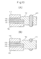
- a seal portion 300 for the separator can be formed by the resin frame 160 itself, as shown in Figure 9 .
- a seal member 400 for the separator can be inserted when molding the frame or, as shown in Figure 10(B) , a seal member 410 can be formed in integral fashion by double molding.
- a positioning member 500 for the separator can be formed by the resin frame 160 itself, as shown in Figure 11 .
- a reinforcing member 600 formed from fine wire, mesh, fiber, etc., can be inserted in the resin frame 160, as shown in Figure 12 .
- Specific methods, including double molding, for providing such additional features to the resin frame can be easily understood and practiced by any person skilled in the technical field of die molding.
- the polymer electrolyte membrane used in the membrane electrode assembly according to the present invention is not specifically limited, but any known polymer electrolyte membrane can be used, as long as it has high proton (H + ) conductivity, is electronically insulative, and is impermeable to gasses.
- a typical example is a resin that has a fluorine-containing polymer as the backbone and has a group such as a sulfonic acid group, a carboxyl group, a phosphoric acid group, a phosphonate group, etc.
- the thickness of the polymer electrolyte membrane greatly affects resistance, it is required that the thickness be made as small as possible, as long as it does not impair the electronic insulation and gas impermeability; specifically, the thickness is chosen to fall within a range of 5 to 50 ⁇ m, and preferably within a range of 10 to 30 ⁇ m.
- Typical examples of the polymer electrolyte membrane include Nafion (registered trademark) membrane (manufactured by DuPont), which is a perfluoro polymer having a phosphoric acid group as a side chain, and Flemion (registered trademark) membrane (manufactured by Asahi Glass).
- GORE-SELECT registered trademark (manufactured by Japan Gore-Tex), which is a reinforced polymer electrolyte membrane formed by impregnating an ion exchange resin into a microporous stretched polytetrafluoroethylene membrane, can also be used advantageously.
- the electrode layer used in the membrane electrode assembly according to the present invention is not specifically limited, but any prior known one can be used, as long as it contains catalyst particles and an ion exchange resin.
- the catalyst is usually formed from an electrically conductive material loaded with catalyst particles.
- any material that exhibits catalytic activity for the oxidation reaction of hydrogen or the reduction reaction of oxygen can be used, examples including platinum (Pt) and other noble metals, or iron, chromium, nickel, etc. and their alloys.
- platinum (Pt) and other noble metals platinum
- iron, chromium, nickel, etc. and their alloys examples including platinum (Pt) and other noble metals, or iron, chromium, nickel, etc. and their alloys.
- carbon-based particles such as carbon black, activated carbon, graphite, etc., are preferable, and among others, fine powered particles are preferably used.
- noble metal particles for example, Pt particles, or alloy particles of Pt and some other metal are carried on carbon black particles having a area of 20 m 2 /g or larger.
- a fuel such as methanol, that contains carbon monoxide (CO)
- the ion exchange resin in the electrode layer is a material that supports the catalyst and serves as a binder for forming the electrode layer, and has the role of forming a passage through which ions, etc., formed by catalyst reaction move.
- the electrode layer in a porous structure to maximize the area where the catalyst makes contact with the fuel gas, such as hydrogen or methanol, at the anode and the oxidizer gas, such as oxygen or air, at the cathode.
- the amount of catalyst contained in the electrode layer is preferably within a range of 0.01 to 1 mg/cm 2 , and more preferably within a range of 0.1 to 0.5 mg/cm 2 .
- the thickness of the electrode layer is generally within a range of 1 to 20 ⁇ m, and preferably within a range of 5 to 15 ⁇ m.
- the gas diffusion layer used in the membrane electrode assembly according to the present invention is a sheet material having electrical conductivity and air permeability.
- a typical example is one prepared by applying water-repellent treatment to an air permeable, electrically conductive matrix such as carbon paper, carbon fabric, nonwoven fabric, carbon felt, etc.
- a porous sheet formed from carbon-based particles and a fluorine-based resin For example, use may be made of a porous sheet prepared by molding carbon black into a sheet using polytetrafluoroethylene as a binder.
- the thickness of the gas diffusion layer is generally within a range of 50 to 500 ⁇ m, and preferably within a range of 100 to 200 ⁇ m.
- the membrane-electrode structure or the membrane-electrode structure precursor sheet is fabricated by joining together the electrode layer, the gas diffusion layer, and the polymer electrolyte membrane.
- any prior known method can be employed, as long as closely compacted joining with low contact resistance can be accomplished without damaging the polymer electrolyte membrane.
- an anode electrode or a cathode electrode can first be formed by combining the electrode layer with the gas diffusion layer, and then be joined to the polymer electrolyte membrane.
- an electrode layer forming coating liquid that contains catalyst particles and an ion exchange resin is prepared using a suitable solvent, and the liquid thus prepared is applied over a gas diffusion layer forming sheet member, thereby forming an anode electrode or a cathode electrode, and the resulting structure can be joined to the polymer electrolyte membrane by hot pressing.
- the electrode layer may first be combined with the polymer electrolyte membrane, and then the gas diffusion layer may be bonded to the electrode layer side.
- a prior known method such as a screen printing method, a spray coating method, or a decal method, should be used.
- the use of a resin material that exhibits good stability i.e., heat resistance, acid resistance, hydrolytic resistance, creep resistance, etc. in the normal operating environment of the fuel cell, is a prerequisite.
- the resin material has a property suitable for die molding, in particular, high flowability during molding.
- the resin material is a thermoplastic resin, it is preferable that its molding shrinkage is small, and if it is a thermosetting resin, it is preferable that its curing shrinkage is small.
- thermoplastic resin examples include plastics or elastomers such as a liquid crystal polymer (LCP), polyphenylene sulfide (PPS), polyether sulfone (PES), polysulfone (PSF), polyether ether ketone (PEEK), polyimide (PI), polybutylene terephthalate (PBT), polyamide (PA), polypropylene (PP), polyurethane, polyolefin, etc.
- thermosetting resin examples include plastics or elastomers such as an epoxy resin, phenol resin, dicyclopentadiene resin, silicone rubber, fluoro rubber, ethylene propylenediene rubber (EPDM), etc.
- the resin frame used in the membrane electrode assembly according to the present invention is applied by die molding.
- Die molding includes injection molding, reaction injection molding, transfer molding, compression molding, cast molding, etc., and a person skilled in the art can select a suitable molding method that matches the properties of the resin used. Since the MEA to which the resin frame is applied is as thin as several hundred micrometers, the mold for forming the resin frame must be made to fit this requirement. Further, to prevent the flimsy MEA from being crushed when clamping the mold, it is preferable to provide the mold with a telescopic structure so as to adjust the thickness of the MEA portion. It is also preferable to provide the mold with a suction mechanism for holding the MEA fixed in place to prevent the MEA from being displaced when clamping the mold. Among others, injection molding, reaction injection molding, and transfer molding are advantageous in that the series of operations such as the placement of the insert, molding, extraction of the molding, etc., can be fully automated.
- a fuel cell stack can be assembled by stacking 10 to 100 cells, each comprising the membrane electrode assembly fabricated in the above manner, alternately between separator plates and cooling sections with the anode and cathode of each cell located on the designated sides.
- MEA membrane electrode assembly
- a platinum-loaded carbon catalyst layer PRIMEA 5510 (registered trademark) (manufactured by Japan Gore-Tex) having a size of 15 ⁇ 15 cm and carrying platinum in an amount of 0.3 mg/cm 2 was deposited as an electrode on one side of a polymer electrolyte membrane formed from an ion exchange membrane GORE-SELECT (registered trademark) (manufactured by Japan Gore-Tex) having a size of 15 ⁇ 15 cm and a thickness of 15 ⁇ m.
- PRIMEA 5510 registered trademark
- GORE-SELECT registered trademark
- a gas diffusion layer CARBEL registered trademark (manufactured by Japan Gore-Tex, CNW10A) having a size of 15 ⁇ 15 cm and a thickness of 150 ⁇ m was deposited as a diffusion layer on the electrode, to form a membrane-electrode structure precursor sheet.
- CNW10A a gas diffusion layer having a size of 15 ⁇ 15 cm and a thickness of 150 ⁇ m was deposited as a diffusion layer on the electrode, to form a membrane-electrode structure precursor sheet.
- two differently sized membrane-electrode structure precursor units one measuring 52 ⁇ 52 mm and the other 56 ⁇ 56 mm, were segmented from the membrane-electrode structure precursor sheet.
- the corners of the 52 ⁇ 52 mm membrane-electrode structure precursor unit were each rounded with a radius of curvature of 1.0 mm.
- the two membrane-electrode structure precursor units were placed with their centers aligned and their polymer electrolyte membranes facing each other, and then bonded together under heat and pressure (160°C, 9.8 ⁇ 10 5 Pa, 5 minutes) by using a hot press. After that, the corners of the 56 ⁇ 56 mm membrane-electrode structure precursor unit were each rounded with a radius of curvature of 2.0 mm, to complete the fabrication of the MEA.
- a mold for forming a resin frame around the MEA was made.
- the mold was chosen to have a form size of 76 ⁇ 76 mm and a form thickness of 0.35 mm.
- the mold was provided with a telescopic structure so as to be able to adjust the thickness of the MEA relatively freely in order to prevent the MEA from being excessively crushed.
- the mold was provided with a suction mechanism for holding the MEA fixed in place to prevent the MEA from being displaced when clamping the mold.
- the mold cavity was provide with four gates corresponding to four resin introduction positions I R such as shown in Figure 6 .
- the above mold was installed on an injection molding machine (SE-100D, manufactured by Sumitomo Heavy Industries).
- the resin (Vectra D408, manufactured by Polyplastics) for forming the resin frame was dried at 140°C for four hours in a hot air drier.
- the thus dried resin was placed into the hopper of the injection molding machine, and the resin was heated to 330°C.
- an automatic transfer machine manufactured by Yushin Precision Equipment
- the MEA was placed in a designated position within the mold by aligning the four gates with the respective resin introduction positions.
- the MEA was held fixed in place by operating the MEA holding suction mechanism and, in this condition, the mold was clamped.
- the resin was injected at a rate of 250 mm/second and, after cooling, the membrane electrode assembly with the resin frame applied thereto was recovered using the automatic transfer machine.
- a membrane electrode assembly provided with a resin frame having a shape such as shown in Figure 11 was fabricated in the same manner as Example 1, except that a projection having a step height of 0.005 mm was provided when making the mold. It was confirmed that, even with the step height as small as 0.005 mm, the desired projection shape can be conferred to the resin frame in accordance with the method of the present invention.
- a platinum-loaded carbon catalyst layer PRIMEA 5510 (registered trademark) (manufactured by Japan Gore-Tex) having a size of 5 ⁇ 5 cm and carrying platinum in an amount of 0.3 mg/cm 2 was deposited as an electrode on each side of a polymer electrolyte membrane formed from an ion exchange membrane GORE-SELECT (registered trademark) (manufactured by Japan Gore-Tex) having a size of 7.6 ⁇ 7.6 cm and a thickness of 30 ⁇ m.
- a gas diffusion layer CARBEL registered trademark (manufactured by Japan Gore-Tex, CNW10A) having a size of 5 ⁇ 5 cm and a thickness of 150 ⁇ m was deposited as a diffusion layer on each electrode, to obtain an MEA having an electrolyte membrane size of 7.6 ⁇ 7.6 cm and an electrode size of 5 ⁇ 5 cm.
- the resin frame was injection-molded in the same manner as Example 1, to produce the membrane electrode assembly with the resin frame applied thereto.
- a platinum-loaded carbon catalyst layer PRIMEA 5510 (registered trademark) (manufactured by Japan Gore-Tex) having a size of 8 ⁇ 8 cm and carrying platinum in an amount of 0.3 mg/cm 2 was deposited as an electrode on each side of a polymer electrolyte membrane formed from an ion exchange membrane GORE-SELECT (registered trademark) (manufactured by Japan Gore-Tex) having a size of 8 ⁇ 8 cm and a thickness of 30 ⁇ m.
- a gas diffusion layer CARBEL (registered trademark) (manufactured by Japan Gore-Tex, CNW10A) having a size of 8 ⁇ 8 cm and a thickness of 150 ⁇ m was deposited as a diffusion layer on each electrode, to form a membrane-electrode structure precursor sheet having an electrolyte membrane size of 8 ⁇ 8 cm and an electrode size of 8 ⁇ 8 cm.
- an MEA measuring 52 ⁇ 52 mm was segmented from the membrane-electrode structure precursor sheet. The corners of the MEA were each rounded with a radius of curvature of 1.0 mm.
- the resin frame was injection-molded in the same manner as Example 1, to produce the membrane electrode assembly with the resin frame applied thereto.
- a resin frame was produced by forming a hole having outer dimensions of 51.5 ⁇ 51.5 mm in the center of a resin film (TORELINA, manufactured by Toray) having a thickness of 0.35 mm and outer dimensions of 76 ⁇ 76 mm.
- TORELINA manufactured by Toray
- the resin frame was placed on the MEA with the inner circumference of the former evenly overlapping the outer circumference of the latter; then, the MEA was press-fitted into the resin frame under heat and pressure (200°C, 9.8 ⁇ 10 5 Pa, 3 minutes) by using a hot press, to produce the membrane electrode assembly with the resin frame applied thereto.
- a leak test was conducted to check the reliability of the seal in the solid polymer electrolyte fuel cell having the membrane electrode assembly fabricated in each example.
- the membrane electrode assembly was set in a jig mimicking a cell, and the entire assembly was immersed in water; in this condition, compressed air was fed into one side of the membrane electrode assembly, and generation of bubbles from the opposite side was checked. At this time, the pressure of the compressed air was gradually raised from 0 MPa, and the pressure at which bubbles were generated from the opposite side was recorded as a leak pressure.
- Example 1 In the above leak test, the membrane electrode assembly of Example 1 recorded a leak pressure of 0.3 MPa or higher. On the other hand, in the membrane electrode assemblies of Example 3 (Comparative Example), Example 4 (Comparative Example), and Example 5 (Comparative Example), bubbles were generated immediately after the pressure was raised (that is, the moment the pressure was applied).
- the reliability, mechanical strength, and handling characteristics of the seal in the solid polymer electrolyte fuel cell are enhanced. Because of the enhanced mechanical strength and handling characteristics, a fuel cell stack can be assembled with good accuracy and in a simple manner. Further, according to the present invention, the manufacturing cost of the solid polymer electrolyte fuel cell is reduced by reducing the required area size of the electrolyte membrane. Furthermore, according to the present invention, the production efficiency of the solid polymer electrolyte fuel cell is enhanced by reducing the number of fabrication steps.
Landscapes
- Chemical & Material Sciences (AREA)
- Chemical Kinetics & Catalysis (AREA)
- Electrochemistry (AREA)
- General Chemical & Material Sciences (AREA)
- Engineering & Computer Science (AREA)
- Manufacturing & Machinery (AREA)
- Life Sciences & Earth Sciences (AREA)
- Sustainable Development (AREA)
- Sustainable Energy (AREA)
- Fuel Cell (AREA)
- Inert Electrodes (AREA)
Applications Claiming Priority (2)
| Application Number | Priority Date | Filing Date | Title |
|---|---|---|---|
| JP2006211639A JP5164348B2 (ja) | 2006-08-03 | 2006-08-03 | 膜電極組立体およびその製造方法ならびにそれを用いた固体高分子形燃料電池 |
| PCT/JP2007/065572 WO2008016185A1 (fr) | 2006-08-03 | 2007-08-02 | ensemble électrode à membrane, SON PROCESSUS DE FABRICATION, et pile à combustible polymère solide L'utilisant |
Publications (4)
| Publication Number | Publication Date |
|---|---|
| EP2048730A1 true EP2048730A1 (de) | 2009-04-15 |
| EP2048730A4 EP2048730A4 (de) | 2010-07-21 |
| EP2048730B1 EP2048730B1 (de) | 2012-04-04 |
| EP2048730B8 EP2048730B8 (de) | 2012-05-02 |
Family
ID=38997351
Family Applications (1)
| Application Number | Title | Priority Date | Filing Date |
|---|---|---|---|
| EP07792234A Not-in-force EP2048730B8 (de) | 2006-08-03 | 2007-08-02 | Membranelektrodenbaugruppe, verfahren zu ihrer herstellung und festpolymer-brennstoffzelle damit |
Country Status (8)
| Country | Link |
|---|---|
| US (1) | US8685588B2 (de) |
| EP (1) | EP2048730B8 (de) |
| JP (1) | JP5164348B2 (de) |
| KR (1) | KR101473500B1 (de) |
| CN (1) | CN101523647B (de) |
| AT (1) | ATE552620T1 (de) |
| CA (1) | CA2659193C (de) |
| WO (1) | WO2008016185A1 (de) |
Cited By (6)
| Publication number | Priority date | Publication date | Assignee | Title |
|---|---|---|---|---|
| EP2466674A4 (de) * | 2009-08-12 | 2014-01-08 | Gore W L & Ass Co Ltd | Verfahren zur herstellung einer verstärkten membranelektrodenanordnung und verstärkte membranelektrodenanordnung |
| EP2736108A4 (de) * | 2011-07-19 | 2015-01-07 | Nok Corp | Brennstoffzellendichtung |
| CN104885275A (zh) * | 2012-12-27 | 2015-09-02 | 日产自动车株式会社 | 膜电极接合体及膜电极接合体的制造方法 |
| EP2668689A4 (de) * | 2011-01-28 | 2016-07-20 | Audi Ag | Brennstoffzellendichtung |
| US10593978B2 (en) | 2004-12-28 | 2020-03-17 | Audi Ag | MEA seal structure containing catalyzed layer |
| WO2020074166A1 (de) * | 2018-10-10 | 2020-04-16 | Robert Bosch Gmbh | Dichtungskörper für eine brennstoffzelle und verfahren zum herstellen einer solchen brennstoffzelle |
Families Citing this family (39)
| Publication number | Priority date | Publication date | Assignee | Title |
|---|---|---|---|---|
| JP5321801B2 (ja) * | 2008-10-31 | 2013-10-23 | Nok株式会社 | 燃料電池 |
| JP5097158B2 (ja) * | 2009-04-01 | 2012-12-12 | 東海ゴム工業株式会社 | 燃料電池用セルアセンブリの製造方法、および燃料電池の製造方法 |
| JP5097159B2 (ja) | 2009-04-01 | 2012-12-12 | 東海ゴム工業株式会社 | 燃料電池モジュールの製造方法、および燃料電池の製造方法 |
| JP5585427B2 (ja) * | 2010-12-08 | 2014-09-10 | トヨタ自動車株式会社 | 膜電極接合体およびそれを用いた燃料電池 |
| JP5549578B2 (ja) * | 2010-12-22 | 2014-07-16 | トヨタ自動車株式会社 | 燃料電池 |
| JP5236024B2 (ja) | 2011-01-12 | 2013-07-17 | 本田技研工業株式会社 | 燃料電池 |
| JP5936045B2 (ja) * | 2011-04-12 | 2016-06-15 | Toto株式会社 | 固体酸化物形燃料電池 |
| JP5824522B2 (ja) | 2011-09-22 | 2015-11-25 | 本田技研工業株式会社 | 燃料電池用樹脂枠付き電解質膜・電極構造体 |
| JP5756388B2 (ja) * | 2011-10-20 | 2015-07-29 | 本田技研工業株式会社 | 燃料電池 |
| CN103094593B (zh) | 2011-11-01 | 2015-08-05 | 本田技研工业株式会社 | 燃料电池 |
| JP5683433B2 (ja) * | 2011-11-07 | 2015-03-11 | 本田技研工業株式会社 | 燃料電池スタック |
| JP5855442B2 (ja) | 2011-12-15 | 2016-02-09 | 本田技研工業株式会社 | 燃料電池用樹脂枠付き電解質膜・電極構造体の製造方法 |
| US8895202B2 (en) * | 2012-01-13 | 2014-11-25 | Honda Motor Co., Ltd. | Fuel cell membrane electrode assembly |
| JP5936889B2 (ja) | 2012-03-09 | 2016-06-22 | 本田技研工業株式会社 | 燃料電池 |
| US9799898B2 (en) | 2012-03-23 | 2017-10-24 | Honda Motor Co., Ltd. | Fuel cell |
| JP6006956B2 (ja) * | 2012-03-26 | 2016-10-12 | 本田技研工業株式会社 | 燃料電池 |
| JP5855540B2 (ja) | 2012-07-03 | 2016-02-09 | 本田技研工業株式会社 | 燃料電池用樹脂枠付き電解質膜・電極構造体 |
| JP5945481B2 (ja) | 2012-09-18 | 2016-07-05 | 本田技研工業株式会社 | 燃料電池の製造方法 |
| CN105074987B (zh) * | 2013-01-18 | 2018-04-17 | 戴姆勒股份公司 | 包括粘接到膜电极组件和流场板的框架薄片的燃料电池组件 |
| JP6037905B2 (ja) | 2013-03-21 | 2016-12-07 | 本田技研工業株式会社 | 燃料電池用樹脂枠付き電解質膜・電極構造体 |
| JP6025632B2 (ja) | 2013-03-25 | 2016-11-16 | 本田技研工業株式会社 | 燃料電池 |
| CN107293767B (zh) | 2013-09-17 | 2020-07-17 | 本田技研工业株式会社 | 燃料电池堆 |
| JP6118225B2 (ja) | 2013-10-09 | 2017-04-19 | 本田技研工業株式会社 | 燃料電池用樹脂枠付き電解質膜・電極構造体 |
| JP6278932B2 (ja) * | 2014-08-04 | 2018-02-14 | 本田技研工業株式会社 | 燃料電池用膜−電極接合体及び固体高分子形燃料電池 |
| JP6223307B2 (ja) * | 2014-09-09 | 2017-11-01 | 本田技研工業株式会社 | 燃料電池セル |
| KR101856311B1 (ko) * | 2016-03-10 | 2018-05-09 | 현대자동차주식회사 | 막전극 접합체 및 이를 포함하는 연료전지 |
| EP3499619B1 (de) * | 2016-08-12 | 2020-07-29 | Nissan Motor Co., Ltd. | Vorrichtung zur wiederherstellung von katalysatorverschleiss und verfahren zur wiederherstellung von katalysatorverschleiss |
| JP6427215B2 (ja) * | 2017-03-07 | 2018-11-21 | 本田技研工業株式会社 | 固体高分子型燃料電池用フィルム成形品のプレス加工方法及びプレス加工装置 |
| JP6848799B2 (ja) * | 2017-10-05 | 2021-03-24 | トヨタ自動車株式会社 | 燃料電池の単セルの製造方法 |
| KR102683799B1 (ko) | 2018-12-12 | 2024-07-09 | 현대자동차주식회사 | 연료전지용 탄성체 셀 프레임 및 그 제조방법과 이를 이용한 단위 셀 |
| KR102683801B1 (ko) | 2018-12-12 | 2024-07-09 | 현대자동차주식회사 | 연료전지용 탄성체 셀 프레임 및 그 제조방법과 이를 이용한 단위 셀 |
| CN111380931A (zh) * | 2018-12-28 | 2020-07-07 | 广东美的白色家电技术创新中心有限公司 | 气体传感器 |
| US11038183B2 (en) * | 2019-07-15 | 2021-06-15 | Hyundai Motor Gompany | Apparatus for manufacturing elastomeric cell frame for fuel cell |
| KR20210015384A (ko) * | 2019-08-02 | 2021-02-10 | 현대자동차주식회사 | 연료전지용 탄성체 셀 프레임 및 그 제조방법과 이를 이용한 단위 셀 |
| KR20230001448A (ko) * | 2021-06-28 | 2023-01-04 | 현대자동차주식회사 | 전기 화학 장치 |
| CN115020735B (zh) * | 2022-05-11 | 2024-05-07 | 南方科技大学 | 一种固体氧化物燃料电池及其制备方法和电堆 |
| DE102023210913A1 (de) * | 2023-11-03 | 2025-05-08 | Robert Bosch Gesellschaft mit beschränkter Haftung | Mikrofluidische Vorrichtung und Verfahren zu deren Herstellung |
| WO2025179506A1 (zh) * | 2024-02-28 | 2025-09-04 | 罗伯特·博世有限公司 | 电极隔膜单元、制备方法、电解槽单元及能源制氢设备 |
| DE102024209880A1 (de) | 2024-10-10 | 2026-04-16 | Robert Bosch Gesellschaft mit beschränkter Haftung | Elektrochemische Zelle |
Family Cites Families (14)
| Publication number | Priority date | Publication date | Assignee | Title |
|---|---|---|---|---|
| JPH03101059A (ja) * | 1989-09-14 | 1991-04-25 | Yamaha Motor Co Ltd | リン酸型燃料電池のシール構造 |
| JPH10199551A (ja) | 1997-01-06 | 1998-07-31 | Honda Motor Co Ltd | 燃料電池構造体およびその製造方法 |
| JP3754596B2 (ja) | 2000-05-12 | 2006-03-15 | 株式会社リコー | 光情報記録再生装置 |
| JP3648128B2 (ja) * | 2000-05-02 | 2005-05-18 | 本田技研工業株式会社 | 燃料電池 |
| WO2002019454A1 (fr) * | 2000-08-30 | 2002-03-07 | Sanyo Electric Co., Ltd. | Unite de cellule electrochimique et son procede de fabrication |
| JP2002313371A (ja) | 2000-12-07 | 2002-10-25 | Sanyo Electric Co Ltd | 燃料電池セルユニット |
| JP5208338B2 (ja) * | 2001-06-29 | 2013-06-12 | 本田技研工業株式会社 | 電解質膜・電極構造体及び燃料電池セル |
| JP4818546B2 (ja) * | 2001-08-29 | 2011-11-16 | 本田技研工業株式会社 | 膜・電極構造体 |
| EP1472751A2 (de) * | 2002-01-22 | 2004-11-03 | E.I. du Pont de Nemours and Company | Verbundene membranelektrodeneinheit und deren herstellung |
| US7687181B2 (en) * | 2002-04-23 | 2010-03-30 | Protonex Technology Corporation | Channel-based electrochemical cassettes |
| JP4121340B2 (ja) * | 2002-09-04 | 2008-07-23 | 本田技研工業株式会社 | 燃料電池 |
| US20050014056A1 (en) * | 2003-07-14 | 2005-01-20 | Umicore Ag & Co. Kg | Membrane electrode unit for electrochemical equipment |
| JP2005339891A (ja) * | 2004-05-25 | 2005-12-08 | Mitsubishi Electric Corp | 固体高分子形燃料電池 |
| JP5194346B2 (ja) * | 2005-08-31 | 2013-05-08 | 日産自動車株式会社 | 電解質膜−電極接合体 |
-
2006
- 2006-08-03 JP JP2006211639A patent/JP5164348B2/ja not_active Expired - Fee Related
-
2007
- 2007-08-02 CA CA2659193A patent/CA2659193C/en active Active
- 2007-08-02 AT AT07792234T patent/ATE552620T1/de active
- 2007-08-02 KR KR1020097004392A patent/KR101473500B1/ko not_active Expired - Fee Related
- 2007-08-02 WO PCT/JP2007/065572 patent/WO2008016185A1/ja not_active Ceased
- 2007-08-02 US US12/374,681 patent/US8685588B2/en active Active
- 2007-08-02 EP EP07792234A patent/EP2048730B8/de not_active Not-in-force
- 2007-08-02 CN CN2007800369739A patent/CN101523647B/zh not_active Expired - Fee Related
Cited By (10)
| Publication number | Priority date | Publication date | Assignee | Title |
|---|---|---|---|---|
| US10593978B2 (en) | 2004-12-28 | 2020-03-17 | Audi Ag | MEA seal structure containing catalyzed layer |
| EP2466674A4 (de) * | 2009-08-12 | 2014-01-08 | Gore W L & Ass Co Ltd | Verfahren zur herstellung einer verstärkten membranelektrodenanordnung und verstärkte membranelektrodenanordnung |
| US9385387B2 (en) | 2009-08-12 | 2016-07-05 | W. L. Gore & Associates, Co, Ltd. | Method for manufacturing reinforced membrane electrode assembly and reinforced membrane electrode assembly |
| US9806354B2 (en) | 2009-08-12 | 2017-10-31 | W. L. Gore & Associates, Co., Ltd. | Method for manufacturing reinforced membrane electrode assembly and reinforced membrane electrode assembly |
| EP2668689A4 (de) * | 2011-01-28 | 2016-07-20 | Audi Ag | Brennstoffzellendichtung |
| US10103391B2 (en) | 2011-01-28 | 2018-10-16 | Audi Ag | Fuel cell seal |
| EP2736108A4 (de) * | 2011-07-19 | 2015-01-07 | Nok Corp | Brennstoffzellendichtung |
| CN104885275A (zh) * | 2012-12-27 | 2015-09-02 | 日产自动车株式会社 | 膜电极接合体及膜电极接合体的制造方法 |
| EP2940767A4 (de) * | 2012-12-27 | 2015-12-30 | Nissan Motor | Membranelektrodenanordnung und membranelektrodenanordnungsherstellungsverfahren |
| WO2020074166A1 (de) * | 2018-10-10 | 2020-04-16 | Robert Bosch Gmbh | Dichtungskörper für eine brennstoffzelle und verfahren zum herstellen einer solchen brennstoffzelle |
Also Published As
| Publication number | Publication date |
|---|---|
| KR101473500B1 (ko) | 2014-12-16 |
| CA2659193A1 (en) | 2008-02-07 |
| HK1127164A1 (en) | 2009-09-18 |
| JP2008041337A (ja) | 2008-02-21 |
| JP5164348B2 (ja) | 2013-03-21 |
| ATE552620T1 (de) | 2012-04-15 |
| KR20090074154A (ko) | 2009-07-06 |
| CN101523647B (zh) | 2012-04-25 |
| EP2048730B8 (de) | 2012-05-02 |
| EP2048730B1 (de) | 2012-04-04 |
| US8685588B2 (en) | 2014-04-01 |
| CA2659193C (en) | 2012-06-19 |
| WO2008016185A1 (fr) | 2008-02-07 |
| CN101523647A (zh) | 2009-09-02 |
| US20100047649A1 (en) | 2010-02-25 |
| EP2048730A4 (de) | 2010-07-21 |
Similar Documents
| Publication | Publication Date | Title |
|---|---|---|
| US8685588B2 (en) | Membrane electrode assembly, method for producing the same, and solid polymer fuel cell using the same | |
| KR101783060B1 (ko) | 보강된 막 전극 조립체의 제조 방법 및 보강된 막 전극 조립체 | |
| US8551668B2 (en) | Sealing of a membrane electrode assembly | |
| US20070184326A1 (en) | Edge-protected catalyst-coated diffusion media and membrane electrode assemblies | |
| JP5450962B2 (ja) | 膜電極組立体の製造方法 | |
| HK1127164B (en) | Membrane electrode assembly, method for producing the same, and solid polymer fuel cell using the same | |
| JP5774045B2 (ja) | 膜電極組立体の製造方法およびそれにより製造された膜電極組立体 | |
| JP2022170072A (ja) | ガスケットの装着方法 | |
| HK1170077B (en) | Method for manufacturing reinforced membrane electrode assembly |
Legal Events
| Date | Code | Title | Description |
|---|---|---|---|
| PUAI | Public reference made under article 153(3) epc to a published international application that has entered the european phase |
Free format text: ORIGINAL CODE: 0009012 |
|
| 17P | Request for examination filed |
Effective date: 20090129 |
|
| AK | Designated contracting states |
Kind code of ref document: A1 Designated state(s): AT BE BG CH CY CZ DE DK EE ES FI FR GB GR HU IE IS IT LI LT LU LV MC MT NL PL PT RO SE SI SK TR |
|
| AX | Request for extension of the european patent |
Extension state: AL BA HR MK RS |
|
| REG | Reference to a national code |
Ref country code: HK Ref legal event code: DE Ref document number: 1127164 Country of ref document: HK |
|
| A4 | Supplementary search report drawn up and despatched |
Effective date: 20100621 |
|
| GRAP | Despatch of communication of intention to grant a patent |
Free format text: ORIGINAL CODE: EPIDOSNIGR1 |
|
| DAX | Request for extension of the european patent (deleted) | ||
| RIN1 | Information on inventor provided before grant (corrected) |
Inventor name: SUZUKI, YOUICHI Inventor name: FUJIMOTO, HIROYOSHI Inventor name: YAMADA, HIDEKI |
|
| GRAS | Grant fee paid |
Free format text: ORIGINAL CODE: EPIDOSNIGR3 |
|
| GRAA | (expected) grant |
Free format text: ORIGINAL CODE: 0009210 |
|
| AK | Designated contracting states |
Kind code of ref document: B1 Designated state(s): AT BE BG CH CY CZ DE DK EE ES FI FR GB GR HU IE IS IT LI LT LU LV MC MT NL PL PT RO SE SI SK TR |
|
| REG | Reference to a national code |
Ref country code: GB Ref legal event code: FG4D |
|
| REG | Reference to a national code |
Ref country code: CH Ref legal event code: EP |
|
| REG | Reference to a national code |
Ref country code: AT Ref legal event code: REF Ref document number: 552620 Country of ref document: AT Kind code of ref document: T Effective date: 20120415 |
|
| RAP2 | Party data changed (patent owner data changed or rights of a patent transferred) |
Owner name: W.L. GORE & ASSOCIATES, CO., LTD. |
|
| REG | Reference to a national code |
Ref country code: IE Ref legal event code: FG4D |
|
| RIN2 | Information on inventor provided after grant (corrected) |
Inventor name: YAMADA, HIDEKI Inventor name: SUZUKI, YOUICHI Inventor name: FUJIMOTO, HIROYOSHI |
|
| REG | Reference to a national code |
Ref country code: DE Ref legal event code: R096 Ref document number: 602007021764 Country of ref document: DE Effective date: 20120531 |
|
| REG | Reference to a national code |
Ref country code: SE Ref legal event code: TRGR |
|
| REG | Reference to a national code |
Ref country code: NL Ref legal event code: VDEP Effective date: 20120404 |
|
| REG | Reference to a national code |
Ref country code: HK Ref legal event code: GR Ref document number: 1127164 Country of ref document: HK |
|
| REG | Reference to a national code |
Ref country code: AT Ref legal event code: MK05 Ref document number: 552620 Country of ref document: AT Kind code of ref document: T Effective date: 20120404 |
|
| LTIE | Lt: invalidation of european patent or patent extension |
Effective date: 20120404 |
|
| PG25 | Lapsed in a contracting state [announced via postgrant information from national office to epo] |
Ref country code: IS Free format text: LAPSE BECAUSE OF FAILURE TO SUBMIT A TRANSLATION OF THE DESCRIPTION OR TO PAY THE FEE WITHIN THE PRESCRIBED TIME-LIMIT Effective date: 20120804 Ref country code: PL Free format text: LAPSE BECAUSE OF FAILURE TO SUBMIT A TRANSLATION OF THE DESCRIPTION OR TO PAY THE FEE WITHIN THE PRESCRIBED TIME-LIMIT Effective date: 20120404 Ref country code: CY Free format text: LAPSE BECAUSE OF FAILURE TO SUBMIT A TRANSLATION OF THE DESCRIPTION OR TO PAY THE FEE WITHIN THE PRESCRIBED TIME-LIMIT Effective date: 20120404 Ref country code: SI Free format text: LAPSE BECAUSE OF FAILURE TO SUBMIT A TRANSLATION OF THE DESCRIPTION OR TO PAY THE FEE WITHIN THE PRESCRIBED TIME-LIMIT Effective date: 20120404 Ref country code: FI Free format text: LAPSE BECAUSE OF FAILURE TO SUBMIT A TRANSLATION OF THE DESCRIPTION OR TO PAY THE FEE WITHIN THE PRESCRIBED TIME-LIMIT Effective date: 20120404 Ref country code: LT Free format text: LAPSE BECAUSE OF FAILURE TO SUBMIT A TRANSLATION OF THE DESCRIPTION OR TO PAY THE FEE WITHIN THE PRESCRIBED TIME-LIMIT Effective date: 20120404 |
|
| PG25 | Lapsed in a contracting state [announced via postgrant information from national office to epo] |
Ref country code: GR Free format text: LAPSE BECAUSE OF FAILURE TO SUBMIT A TRANSLATION OF THE DESCRIPTION OR TO PAY THE FEE WITHIN THE PRESCRIBED TIME-LIMIT Effective date: 20120705 Ref country code: PT Free format text: LAPSE BECAUSE OF FAILURE TO SUBMIT A TRANSLATION OF THE DESCRIPTION OR TO PAY THE FEE WITHIN THE PRESCRIBED TIME-LIMIT Effective date: 20120806 Ref country code: LV Free format text: LAPSE BECAUSE OF FAILURE TO SUBMIT A TRANSLATION OF THE DESCRIPTION OR TO PAY THE FEE WITHIN THE PRESCRIBED TIME-LIMIT Effective date: 20120404 |
|
| PG25 | Lapsed in a contracting state [announced via postgrant information from national office to epo] |
Ref country code: BE Free format text: LAPSE BECAUSE OF FAILURE TO SUBMIT A TRANSLATION OF THE DESCRIPTION OR TO PAY THE FEE WITHIN THE PRESCRIBED TIME-LIMIT Effective date: 20120404 |
|
| PG25 | Lapsed in a contracting state [announced via postgrant information from national office to epo] |
Ref country code: RO Free format text: LAPSE BECAUSE OF FAILURE TO SUBMIT A TRANSLATION OF THE DESCRIPTION OR TO PAY THE FEE WITHIN THE PRESCRIBED TIME-LIMIT Effective date: 20120404 Ref country code: SK Free format text: LAPSE BECAUSE OF FAILURE TO SUBMIT A TRANSLATION OF THE DESCRIPTION OR TO PAY THE FEE WITHIN THE PRESCRIBED TIME-LIMIT Effective date: 20120404 Ref country code: AT Free format text: LAPSE BECAUSE OF FAILURE TO SUBMIT A TRANSLATION OF THE DESCRIPTION OR TO PAY THE FEE WITHIN THE PRESCRIBED TIME-LIMIT Effective date: 20120404 Ref country code: DK Free format text: LAPSE BECAUSE OF FAILURE TO SUBMIT A TRANSLATION OF THE DESCRIPTION OR TO PAY THE FEE WITHIN THE PRESCRIBED TIME-LIMIT Effective date: 20120404 Ref country code: NL Free format text: LAPSE BECAUSE OF FAILURE TO SUBMIT A TRANSLATION OF THE DESCRIPTION OR TO PAY THE FEE WITHIN THE PRESCRIBED TIME-LIMIT Effective date: 20120404 Ref country code: CZ Free format text: LAPSE BECAUSE OF FAILURE TO SUBMIT A TRANSLATION OF THE DESCRIPTION OR TO PAY THE FEE WITHIN THE PRESCRIBED TIME-LIMIT Effective date: 20120404 Ref country code: EE Free format text: LAPSE BECAUSE OF FAILURE TO SUBMIT A TRANSLATION OF THE DESCRIPTION OR TO PAY THE FEE WITHIN THE PRESCRIBED TIME-LIMIT Effective date: 20120404 |
|
| PLBE | No opposition filed within time limit |
Free format text: ORIGINAL CODE: 0009261 |
|
| STAA | Information on the status of an ep patent application or granted ep patent |
Free format text: STATUS: NO OPPOSITION FILED WITHIN TIME LIMIT |
|
| 26N | No opposition filed |
Effective date: 20130107 |
|
| REG | Reference to a national code |
Ref country code: CH Ref legal event code: PL |
|
| PG25 | Lapsed in a contracting state [announced via postgrant information from national office to epo] |
Ref country code: MC Free format text: LAPSE BECAUSE OF NON-PAYMENT OF DUE FEES Effective date: 20120831 |
|
| PG25 | Lapsed in a contracting state [announced via postgrant information from national office to epo] |
Ref country code: ES Free format text: LAPSE BECAUSE OF FAILURE TO SUBMIT A TRANSLATION OF THE DESCRIPTION OR TO PAY THE FEE WITHIN THE PRESCRIBED TIME-LIMIT Effective date: 20120715 Ref country code: CH Free format text: LAPSE BECAUSE OF NON-PAYMENT OF DUE FEES Effective date: 20120831 Ref country code: LI Free format text: LAPSE BECAUSE OF NON-PAYMENT OF DUE FEES Effective date: 20120831 |
|
| REG | Reference to a national code |
Ref country code: DE Ref legal event code: R097 Ref document number: 602007021764 Country of ref document: DE Effective date: 20130107 |
|
| REG | Reference to a national code |
Ref country code: IE Ref legal event code: MM4A |
|
| PG25 | Lapsed in a contracting state [announced via postgrant information from national office to epo] |
Ref country code: BG Free format text: LAPSE BECAUSE OF FAILURE TO SUBMIT A TRANSLATION OF THE DESCRIPTION OR TO PAY THE FEE WITHIN THE PRESCRIBED TIME-LIMIT Effective date: 20120704 Ref country code: IE Free format text: LAPSE BECAUSE OF NON-PAYMENT OF DUE FEES Effective date: 20120802 |
|
| PG25 | Lapsed in a contracting state [announced via postgrant information from national office to epo] |
Ref country code: MT Free format text: LAPSE BECAUSE OF FAILURE TO SUBMIT A TRANSLATION OF THE DESCRIPTION OR TO PAY THE FEE WITHIN THE PRESCRIBED TIME-LIMIT Effective date: 20120404 |
|
| PG25 | Lapsed in a contracting state [announced via postgrant information from national office to epo] |
Ref country code: TR Free format text: LAPSE BECAUSE OF FAILURE TO SUBMIT A TRANSLATION OF THE DESCRIPTION OR TO PAY THE FEE WITHIN THE PRESCRIBED TIME-LIMIT Effective date: 20120404 |
|
| PG25 | Lapsed in a contracting state [announced via postgrant information from national office to epo] |
Ref country code: LU Free format text: LAPSE BECAUSE OF NON-PAYMENT OF DUE FEES Effective date: 20120802 |
|
| PG25 | Lapsed in a contracting state [announced via postgrant information from national office to epo] |
Ref country code: HU Free format text: LAPSE BECAUSE OF FAILURE TO SUBMIT A TRANSLATION OF THE DESCRIPTION OR TO PAY THE FEE WITHIN THE PRESCRIBED TIME-LIMIT Effective date: 20070802 |
|
| REG | Reference to a national code |
Ref country code: FR Ref legal event code: PLFP Year of fee payment: 10 |
|
| PGFP | Annual fee paid to national office [announced via postgrant information from national office to epo] |
Ref country code: IT Payment date: 20160722 Year of fee payment: 10 |
|
| PGFP | Annual fee paid to national office [announced via postgrant information from national office to epo] |
Ref country code: SE Payment date: 20160726 Year of fee payment: 10 |
|
| REG | Reference to a national code |
Ref country code: FR Ref legal event code: PLFP Year of fee payment: 11 |
|
| PG25 | Lapsed in a contracting state [announced via postgrant information from national office to epo] |
Ref country code: SE Free format text: LAPSE BECAUSE OF NON-PAYMENT OF DUE FEES Effective date: 20170803 |
|
| REG | Reference to a national code |
Ref country code: FR Ref legal event code: PLFP Year of fee payment: 12 |
|
| PG25 | Lapsed in a contracting state [announced via postgrant information from national office to epo] |
Ref country code: IT Free format text: LAPSE BECAUSE OF NON-PAYMENT OF DUE FEES Effective date: 20170802 |
|
| PGFP | Annual fee paid to national office [announced via postgrant information from national office to epo] |
Ref country code: GB Payment date: 20230720 Year of fee payment: 17 |
|
| PGFP | Annual fee paid to national office [announced via postgrant information from national office to epo] |
Ref country code: FR Payment date: 20230720 Year of fee payment: 17 Ref country code: DE Payment date: 20230720 Year of fee payment: 17 |
|
| REG | Reference to a national code |
Ref country code: DE Ref legal event code: R119 Ref document number: 602007021764 Country of ref document: DE |
|
| GBPC | Gb: european patent ceased through non-payment of renewal fee |
Effective date: 20240802 |
|
| PG25 | Lapsed in a contracting state [announced via postgrant information from national office to epo] |
Ref country code: DE Free format text: LAPSE BECAUSE OF NON-PAYMENT OF DUE FEES Effective date: 20250301 |
|
| PG25 | Lapsed in a contracting state [announced via postgrant information from national office to epo] |
Ref country code: GB Free format text: LAPSE BECAUSE OF NON-PAYMENT OF DUE FEES Effective date: 20240802 |
|
| PG25 | Lapsed in a contracting state [announced via postgrant information from national office to epo] |
Ref country code: FR Free format text: LAPSE BECAUSE OF NON-PAYMENT OF DUE FEES Effective date: 20240831 |