EP2048731A1 - Composition de résine pour séparateur de pile à combustible et séparateur de pile à combustible fabriqué à partir de cette composition - Google Patents
Composition de résine pour séparateur de pile à combustible et séparateur de pile à combustible fabriqué à partir de cette composition Download PDFInfo
- Publication number
- EP2048731A1 EP2048731A1 EP08017822A EP08017822A EP2048731A1 EP 2048731 A1 EP2048731 A1 EP 2048731A1 EP 08017822 A EP08017822 A EP 08017822A EP 08017822 A EP08017822 A EP 08017822A EP 2048731 A1 EP2048731 A1 EP 2048731A1
- Authority
- EP
- European Patent Office
- Prior art keywords
- resin composition
- molecular weight
- compound
- fuel cell
- epoxy resin
- Prior art date
- Legal status (The legal status is an assumption and is not a legal conclusion. Google has not performed a legal analysis and makes no representation as to the accuracy of the status listed.)
- Granted
Links
Images
Classifications
-
- H—ELECTRICITY
- H01—ELECTRIC ELEMENTS
- H01M—PROCESSES OR MEANS, e.g. BATTERIES, FOR THE DIRECT CONVERSION OF CHEMICAL ENERGY INTO ELECTRICAL ENERGY
- H01M8/00—Fuel cells; Manufacture thereof
- H01M8/02—Details
- H01M8/0202—Collectors; Separators, e.g. bipolar separators; Interconnectors
- H01M8/0204—Non-porous and characterised by the material
- H01M8/0221—Organic resins; Organic polymers
-
- C—CHEMISTRY; METALLURGY
- C08—ORGANIC MACROMOLECULAR COMPOUNDS; THEIR PREPARATION OR CHEMICAL WORKING-UP; COMPOSITIONS BASED THEREON
- C08K—Use of inorganic or non-macromolecular organic substances as compounding ingredients
- C08K3/00—Use of inorganic substances as compounding ingredients
- C08K3/02—Elements
- C08K3/04—Carbon
-
- C—CHEMISTRY; METALLURGY
- C08—ORGANIC MACROMOLECULAR COMPOUNDS; THEIR PREPARATION OR CHEMICAL WORKING-UP; COMPOSITIONS BASED THEREON
- C08K—Use of inorganic or non-macromolecular organic substances as compounding ingredients
- C08K7/00—Use of ingredients characterised by shape
- C08K7/02—Fibres or whiskers
- C08K7/04—Fibres or whiskers inorganic
- C08K7/06—Elements
-
- C—CHEMISTRY; METALLURGY
- C08—ORGANIC MACROMOLECULAR COMPOUNDS; THEIR PREPARATION OR CHEMICAL WORKING-UP; COMPOSITIONS BASED THEREON
- C08L—COMPOSITIONS OF MACROMOLECULAR COMPOUNDS
- C08L63/00—Compositions of epoxy resins; Compositions of derivatives of epoxy resins
-
- H—ELECTRICITY
- H01—ELECTRIC ELEMENTS
- H01M—PROCESSES OR MEANS, e.g. BATTERIES, FOR THE DIRECT CONVERSION OF CHEMICAL ENERGY INTO ELECTRICAL ENERGY
- H01M8/00—Fuel cells; Manufacture thereof
- H01M8/02—Details
- H01M8/0202—Collectors; Separators, e.g. bipolar separators; Interconnectors
- H01M8/0204—Non-porous and characterised by the material
- H01M8/0223—Composites
- H01M8/0226—Composites in the form of mixtures
-
- Y—GENERAL TAGGING OF NEW TECHNOLOGICAL DEVELOPMENTS; GENERAL TAGGING OF CROSS-SECTIONAL TECHNOLOGIES SPANNING OVER SEVERAL SECTIONS OF THE IPC; TECHNICAL SUBJECTS COVERED BY FORMER USPC CROSS-REFERENCE ART COLLECTIONS [XRACs] AND DIGESTS
- Y02—TECHNOLOGIES OR APPLICATIONS FOR MITIGATION OR ADAPTATION AGAINST CLIMATE CHANGE
- Y02E—REDUCTION OF GREENHOUSE GAS [GHG] EMISSIONS, RELATED TO ENERGY GENERATION, TRANSMISSION OR DISTRIBUTION
- Y02E60/00—Enabling technologies; Technologies with a potential or indirect contribution to GHG emissions mitigation
- Y02E60/30—Hydrogen technology
- Y02E60/50—Fuel cells
-
- Y—GENERAL TAGGING OF NEW TECHNOLOGICAL DEVELOPMENTS; GENERAL TAGGING OF CROSS-SECTIONAL TECHNOLOGIES SPANNING OVER SEVERAL SECTIONS OF THE IPC; TECHNICAL SUBJECTS COVERED BY FORMER USPC CROSS-REFERENCE ART COLLECTIONS [XRACs] AND DIGESTS
- Y02—TECHNOLOGIES OR APPLICATIONS FOR MITIGATION OR ADAPTATION AGAINST CLIMATE CHANGE
- Y02P—CLIMATE CHANGE MITIGATION TECHNOLOGIES IN THE PRODUCTION OR PROCESSING OF GOODS
- Y02P70/00—Climate change mitigation technologies in the production process for final industrial or consumer products
- Y02P70/50—Manufacturing or production processes characterised by the final manufactured product
Definitions
- the present invention relates to a fuel cell separator and a resin composition for fuel cell separator which is a molding material therefor.
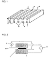
- a fuel cell separator 10 is formed by providing a plurality of partition walls 12 in a protruding state at predetermined intervals on both sides of a flat plate portion 11.
- a number of fuel cell separators 10 are laminated along the protruding direction (the vertical direction in Fig. 1 ) of the partition walls 12. This lamination allows a reactive gas (hydrogen or oxygen) to flow through channels 13 formed by pairs of adjacent partition walls 12.
- the fuel cell separator is produced by molding a resin composition containing a resin material and a conductive material such as graphite into the shape as described above.
- a method for forming the fuel cell separator there is generally used a method in which the above-mentioned resin composition containing a thermosetting resin such as a phenol resin or an epoxy resin as the resin material is placed in a mold provided with flow paths for gas or cooling water, and molded by heat compression molding in which the composition is hot pressed.
- a thermosetting resin such as a phenol resin or an epoxy resin
- attempts have been made to produce the fuel cell separator by injection molding in place of heat compression molding.
- a method of injecting a resin composition containing a graphite material and a thermoplastic resin or a thermosetting resin into a mold from a cylinder, thereby forming a fuel cell separator see Patent Documents 1 to 3).
- the resin composition is transferred to a closed mold through a narrow passage called a runner.
- a runner a narrow passage in which a part of the mold cannot be filled may occur, or high pressure is required for filling, so that the inner pressure of a mold increases to cause deformation of the mold, leading to deterioration of dimensional accuracy of a molded article, in some cases.
- the resin composition is required to have high fluidity.
- a resin which is one of main raw materials of a fuel cell separator resin composition a phenol resin or an epoxy resin is widely used.
- a fuel cell separator having low conductivity is obtained from a phenol resin or an epoxy resin containing a combination of general kinds and amounts of a curing agent and a curing accelerator.
- graphite Referring to a carbon material which is also one of main raw materials of a fuel cell separator resin composition, graphite is widely used.
- the graphite has a hexagonal network plane crystal structure, and electricity is willing to flow in the crystal plane. Therefore, graphite having higher crystallinity in which crystals are developed shows better conductivity.
- graphite crystal has weak bonding in the direction vertical to plane, which links a crystal plane and a crystal plane, and the crystal plane itself has poor reactivity. From those facts, crystal plane tends to trigger a breakage of a fuel cell separator through generation of peeling between crystal planes or interfacial fracture on the crystal plane with a resin material.
- the present invention has been made in view of the above-mentioned circumstances, and an object thereof is to provide a fuel cell separator resin composition having excellent conductivity and fluidity and containing little impurities. Another object of the present invention is to provide a fuel cell separator having excellent conductivity and dimensional accuracy and being accompanied with no fair of causing deterioration in performance of a solid electrolyte.
- the present invention provides the following inventions.
- the fuel cell separator resin composition of the present invention has high strength and contains little impurities, resulting in no fear of causing deterioration in performance of a solid electrolyte. Furthermore, by specifying the curing accelerator to a specific kind or specifying the amount of the curing accelerator to a specific amount, high fluidity can be retained while maintaining conductivity, so that injection molding is possible. Therefore, the fuel cell separator of the present invention has excellent dimensional accuracy, strength and conductivity, and does not lead to deterioration in performance of a solid electrolyte. Thus, a high performance fuel cell is obtained.
- Fig. 1 is a perspective view showing one embodiment of a fuel cell separator.
- Fig. 2 is a schematic view illustrating a method for measuring the resistance in a penetrating direction.
- Fuel cell separator 11 Flat plane portion 12: Partition walls 13: Channels 21: Sample 22: Carbon paper 23: Electrode 24: Ammeter 25: Voltmeter
- the epoxy resin is a compound having two or more epoxy groups, and conventionally known compounds can be used.
- the epoxy resin include bisphenol type epoxy resins such as a bisphenol A type epoxy resin, a bisphenol F type epoxy resin, a bisphenol AF type epoxy resin, a bisphenol S type epoxy resin, a hydrogenated bisphenol A type epoxy resin and a halogenated bisphenol A type epoxy resin; multifunctional epoxy resins such as a phenol novolak type epoxy resin, a cresol novolak type epoxy resin, a bisphenol A novolak type epoxy resin, a tris-hydroxyphenylmethane type epoxy resin, a phenol dicyclopentadiene type epoxy resin, a halogenated phenol novolak type epoxy resin, a naththol novolak type epoxy resin, resorcin epoxide and a tetraphenylolethane type epoxy resin; alicyclic epoxy resins; biphenyl type epoxy resins; naphthalene type epoxy
- the epoxy resin is not limited to those. Of those epoxy resins, the multifunctional epoxy resins are preferably used in the present invention for the reason that a molded article having high heat resistance and strength is obtained.
- the epoxy equivalent is preferably from 50 to 500, and more preferably from 100 to 300. Where the epoxy equivalent is too low, the resulting molded article becomes brittle. On the other hand, where the epoxy equivalent is too high, only a molded article having low heat resistance and strength is obtained.
- the epoxy resin reacts with the curing agent to form an epoxy-cured product.
- Various known compounds can be used as the curing agent.
- the curing agent include aliphatic, alicyclic and aromatic polyamines such as diethylenetriamine, triethylenetetramine, tetraethylenepentamine, menthenediamine, isophoronediamine, N-aminoethylpiperazine, m-xylenediamine and diaminodiphenylmethane, or carbonates thereof; acid anhydrides such as phthalic anhydride, methyltetrahydrophthalic anhydride, methylhexahydrophthalic anhydride, methylnadic anhydride, dodecylsuccinic anhydride, pyromellitic anhydride, benzophenonetetracarboxylic anhydride, trimellitic anhydride and polyazelaic anhydride; polyphenols such as phenol novolak and cresol novolak; and polymercapt
- the curing agent is not limited to those. A plurality of the curing agents can be used in combination.
- curing agents such as polyamines or carbonates thereof, acid anhydrides, polyphenols and polymercaptan are called a polyaddition type curing agent, because they themselves react with an epoxy compound by polyaddition reaction to constitute the epoxy-cured product.
- An excess or deficiency of the polyaddition type curing agent leads to the remaining of unreacted functional groups, and therefore, the amount thereof added has an appropriate range.
- the polyaddition type curing agent is preferably used in an amount of from 0.8 to 1.2 equivalent weight, and particularly from 0.9 to 1.1 equivalent weight, per epoxy group of an epoxy resin precursor.
- the curing rate of the thermosetting resin can arbitrarily be changed by variously selecting the kind and amount of those curing agents, the kind of thermosetting resin and the kind and amount of the curing accelerator.
- One skilled in the art will easily determine the kinds and amounts of thermosetting resin, curing agent and curing accelerator used in accordance with the intended curing conditions.
- a compound having two or more phenolic hydroxyl groups is preferred as the curing agent.
- Examples of such a compound include the above-mentioned polyphenols and bisphenol A, such as phenol novolak, cresol novolak, bisphenol A novolak, aralkyl type phenol novolak, a triphenylmethane type phenol resin, a terpenephenol resin, naphthol novolak and a phenol dicyclopentadiene resin.
- phenol novolak, cresol novolak, bisphenol A novolak, aralkyl type phenol novolak, a triphenylmethane type phenol resin, a terpenephenol resin, naphthol novolak and a phenol dicyclopentadiene resin such as phenol novolak, cresol novolak, bisphenol A novolak, aralkyl type phenol novolak, a triphenylmethane type phenol resin, a terpenephenol resin, naphthol novolak and a phenol dicyclopentadiene resin.
- One of the epoxy resin and the curing agent used must have a softening temperature in a specific range.
- the softening temperature used herein is measured according to the method defined in JIS K7234, a ring and ball method.
- an epoxy resin and a curing agent, having high softening temperature have high molecular weight, and as a result, viscosity during melting tends to increase. Therefore, where the softening temperature is too high, compound viscosity becomes high, resulting in decreasing dimensional accuracy of a fuel cell separator, and making it impossible to ensure fluidity necessary for injection molding.
- the softening temperature of the epoxy resin or the curing agent has a preferred range.
- the softening temperature of the epoxy resin or the curing agent in the present invention is preferably from 40 to 90°C, more preferably from 50 to 85°C, and still more preferably from 55 to 80°C.
- the matter to be considered in selection of the kind and amount of the curing accelerator (C) is that curing reaction of an epoxy resin is difficult to occur in a temperature region of about 100°C or lower which is assumed as a kneading temperature or a cylinder temperature during injection molding, that is, heat stability is high.
- a fuel cell separator having high conductivity is obtained by selecting the kind and amount of the curing accelerator from such a standpoint. The result of consideration on this reason is described hereinafter.
- the preferred characteristics are that a curing reaction rate is fast at a temperature of about 150°C or higher which is assumed as a mold temperature, and reaction initiates rapidly after passing a derivation period of a certain time from the initiation of filling a material into a mold.
- Molding time can be shortened, and additionally, a material can be filled before initiation of a curing reaction. As a result, filling pressure becomes low, resulting in improvement of dimensional accuracy of a molded article.
- the kind and amount of the preferred curing accelerator are specifically described below.
- a phosphine compound represented by the following formula (I) or a phosphonium compound represented by the following formula (II), having a molecular weight of from 300 to 1,000 is used as the curing accelerator.
- R1 to R4 which may be the same or different each represent a functional group selected from hydrogen, an alkyl group, an aralkyl group and an aryl group, or their derivatives; and X is a substance selected from a four-coordinated boron compound, a halogen atom and a six-coordinated antimony compound.
- the phosphorus compound having a molecular weight of from 300 to 1,000 is not particularly limited.
- Examples of the phosphorus compound include tri-o-tolylphosphine (molecular weight: 304), tri-p-tolylphosphine (molecular weight: 304), tri-m-tolylphosphine (molecular weight: 304), tribenzylphosphine (molecular weight: 304), tris(p-methoxyphenyl)phosphine (molecular weight: 352), tris(p-tert-butoxyphenyl)phosphine (molecular weight: 479), tri-2,4-quinolylphosphine (molecular weight: 346), tri-2,5-quinolylphosphine (molecular weight: 346), tri-3,5-quinolylphosphine (molecular weight: 346), tri-n-octylphosphine (molecular weight: 371), tetrabutylphospho
- the molecular weight of the phosphorus compound used in the present invention has a preferred range.
- the molecular weight of the phosphorus compound used in the present invention is from 300 to 1,000, preferably 500 to 800, and still more preferably from 600 to 750.
- the phosphorus compound one containing an aromatic ring, specifically a compound wherein at least one of R1 to R4 in the above formula (I) or (II) is an aralkyl group, an aryl group or a derivative thereof, and a salt of the four-coordinated boron compound in the formula (II) are particularly preferred because they have high heat stability in a temperature region of about 100°C or lower and have high curing reaction rate at a temperature of about 150°C or higher.
- tetraphenylphosphonium tetraphenyl borate and tetraphenylphosphonium tetra-p-tolyl borate are easily available, and have high heat stability in a temperature region of about 100°C or lower and high curing reaction rate at a temperature of about 150°C or higher, and therefore are preferred in the present invention.
- Those phosphorus compounds are generally commercially available, and can easily be available.
- a salt of a diazabicyclo compound and an organic acid is also preferred as the curing accelerator.
- the diazabicyclo compound is not particularly limited, and examples thereof include 1,8-diazabicyclo(5,4,0)undecene-7 (abbreviated to DBU), 1,5-diazabicyclo(4,3,0)nonene-5 (abbreviated to DBN) and 6-dibutylamino-1,8-diazabicyclo(5,4,0)undecene-7.
- the diazabicyclo compound is not limited to those. Above all, 1,8-diazabicyclo(5,4,0)undecene-7 is inexpensive, is easily available, has high stability and is difficult to volatilize, and therefore is a preferred diazabicyclo compound in the present invention.
- organic acid examples include orthophthalic acid (an aromatic multivalent organic acid, acid dissolution constant: 2.95), isophthalic acid (an aromatic multivalent organic acid, acid dissolution constant: 3.48), terephthalic acid (an aromatic multivalent organic acid, acid dissolution constant: 3.54), trimesic acid (an aromatic multivalent organic acid, acid dissolution constant: 3.13), formic acid (acid dissolution constant: 3.55), acetic acid (acid dissolution constant: 4.76), phenol ((an aromatic organic acid, acid dissolution constant: 9.89), benzoic acid (an aromatic organic acid, acid dissolution constant: 4.00), salicylic acid (an aromatic organic acid, acid dissolution constant: 2.75), oxalic acid (a multivalent organic acid, acid dissolution constant: 1.27), cinnamic acid (acid dissolution constant: 4.44), tartaric acid (a multivalent organic acid, acid dissolution constant: 3.04), lactic acid (acid dissolution constant: 3.86), and phenol novolak (a multivalent organic acid, acid dis
- the organic acid is not limited to those. Furthermore, the organic acid is incorporated into the epoxy resin during curing reaction. Therefore, the organic acid having a more inflexible molecular structure and a larger number of reaction sites with the epoxy resin can provide a molded article having higher heat resistance and strength. For this reason, the aromatic organic acid having an inflexible structure and the multivalent organic acid having many reaction sites with the epoxy resin are preferred.
- the salt of the diazabicyclo compound and the organic acid dissociates into the diazabicyclo compound and the organic acid upon heating, and the dissociated diazabicyclo compound acts as the curing accelerator. Accordingly, when the temperature at which the salt of the diazabicyclo compound and the organic acid dissociates is high, a resin composition having high heat stability is obtained.
- the dissociation temperature is proportional to the strength of the organic acid. When the organic acid is strong, the resin composition having high heat stability can be obtained. However, when the organic acid is extremely strong, the salt of the diazabicyclo compound and the organic acid is hydrolyzed by deliquescence of the organic acid to rather decrease heat stability.
- the acid dissolution constant of the organic acid used in the present invention has a preferred range.
- the acid dissolution constant of the organic acid used in the present invention is preferably from 0 to 10, and more preferably from 2 to 4.
- a strong acid such as sulfuric acid or hydrochloric acid is unfavorable, though it depends on the concentration thereof, because the acid dissolution constant thereof sometimes takes a negative value less than 0.
- the aromatic organic acid or the multivalent organic acid is used as the organic acid, the molded article having high heat resistance and strength is obtained.
- orthophthalic acid, isophthalic acid, terephthalic acid and trimesic acid have appropriate acid dissolution constants and also are aromatic multivalent organic acids, so that the resin composition having particularly excellent heat stability, strength and heat resistance can be obtained.
- the acid dissolution constant in the present invention indicates the first-step acid dissolution constant (pKa1) in the case of the multivalent organic acid.
- the salt of the diazabicyclo compound and the organic acid can be produced by the methods which have hitherto been known.
- the salt can be produced by dissolving the diazabicyclo compound and the organic acid in a solvent and mixing, or stirring at a temperature equal to or higher than the melting point of the organic acid.
- the production method is not limited to this method.
- stirring and mixing are preferably performed in an atmosphere of nitrogen such that the diazabicyclo compound and the organic acid are not deteriorated by oxidation.
- the amount of the organic acid is preferably from 10 to 2,000 parts by mass, more preferably from 50 to 500 parts by mass, and still more preferably from 80 to 120 parts by mass, based on 100 parts by mass of the diazabicyclo compound.
- alkyl type urea derivatives represented by the following formulae (III) to (V) are preferred.
- R1 and R2 which may be the same or different each represent hydrogen, halogen, a lower alkyl group, a lower alkoxy group or a nitro group; and R3 and R4 which may be the same or different each represent a lower alkyl group.
- R1 and R2 which may be the same or different each represent hydrogen, halogen, a lower alkyl group, a lower alkoxy group or a nitro group; and R3, R4, R5 and R6 which may be the same or different each represent a lower alkyl group.
- R1, R2, R3 and R4 which may be the same or different each represent a lower alkoxy group; and R5 represents an aliphatic hydrocarbon or a derivative thereof.
- the lower alkyl group or the lower alkoxy group for R3 and R4 in the formula (III), R3 to R6 in the formula (IV) and R1 to R4 in the formula (V) is preferably methyl group, ethyl group, propyl group, or butyl group, or the corresponding alkoxy group.
- alkyl type urea derivative represented by the formula (III) include 3-phenyl-1,1-urea, 3-(p-chlorophenyl)-1,1-urea, 3-(3,4-dichlorophenyl)-1,1-urea, 3-(o-methylphenyl)-1,1-urea, 3-(p-methylphenyl)-1,1-urea, 3-(methoxyphenyl)-1,1-urea and 3-(nitrophenyl)-1,1-urea.
- alkyl type urea derivative represented by the formula (IV) include 1,1'-phenylenebis(3,3-urea) and 1,1'-(4-methyl-m-phenylene)-bis(3,3-urea).
- alkyl type urea derivative represented by the formula (V) includes N,N"-(1,5,5-trimethyl-1,3-cyclohexanesil)bis[N',N'-trimethylurea].
- the resin composition having high heat stability in a temperature region of about 100°C or lower and having high curing reaction rate at a temperature of about 150°C or higher can be obtained.
- the imidazole compound having a molecular weight of 100 or more is preferred as the curing accelerator.
- the imidazole compound is a compound containing imidazole represented by the following chemical formula.
- Examples of the imidazole compound having a molecular weight of 100 or more used in the present invention include 2-undecylimidazole (molecular weight: 224), 2-heptadecylimidazole (molecular weight: 307), 2-ethyl-4-methylimidazole (molecular weight: 110), 2-phenylimidazole (molecular weight: 144), 2-phenyl-4-imidazole (molecular weight: 158), 1-benzyl-2-methylimidazole (molecular weight: 172), 1-benzyl-2-phenylimidazole (molecular weight: 234), 1-cyanoethyl-2-methylimidazole (molecular weight: 135), 1-cyanoethyl-2-ethyl-4-methylimidazole (molecular weight: 163), 1-cyanoethyl-2-undecylimidazole (molecular weight: 275), 1-cyanoethyl-2-phenylim
- the resin composition having high heat stability can be obtained.
- the molecular weight of the imidazole compound used in the present invention has a preferred range.
- the molecular weight of the imidazole compound used in the present invention is from 100 to 500, preferably from 120 to 300, and still more preferably from 150 to 250.
- the imidazole compound preferably contains oxygen.
- the composition in which the curing reaction is hard to proceed during melt kneading is obtained.
- 2-phenyl-4,5-dihydroxymethylimidazole and 2-phenyl-4-methyl-5-hydroxymethylimidazole correspond to such an imidazole compound.
- a tertiary amine compound having a molecular weight of from 120 to 1,000 is preferred as the curing accelerator.
- the tertiary amine compound having a molecular weight of from 120 to 1,000 is not particularly limited.
- Examples of the tertiary amine compound include trisdimethylaminomethylphenol (molecular weight: 265), N,N-dimethylcyclohexylamine (molecular weight: 127), tri-n-butylamine (molecular weight: 185), bis(p-aminohexyl)methane (molecular weight: 210), tetramethyl-1,3-diaminopropane (molecular weight: 130), N,N-dimethylcyclohexylamine (molecular weight: 127), N-ethyl(cyclohexyl)amine (molecular weight: 127), 3-dimethylaminophenol (molecular weight: 137), triphenylamine (molecular weight:
- the tertiary amine compound is not limited to those.
- compounds obtained by adducting (prepolymerizing) an amine compound such as an epoxy amine adduct obtained by prepolymerization utilizing addition reaction between an amine compound such as dialkylamine, and an epoxy resin, can also be used.
- the amine compound has non-covalent ion pair on nitrogen atom, and this promotes reaction between an epoxy resin and the curing agent. Electron density of nitrogen atom increases as the number of hydrocarbon or hydrocarbon derivative bonded to nitrogen increases, resulting in increase of action as the curing accelerator. The number of the hydrocarbon bonded to nitrogen is amine series. Therefore, a tertiary amine has the strongest action as the curing accelerator in the whole amine compounds.
- the resin composition having high heat stability can be obtained.
- the molecular weight is extremely high, there is the problem that curing reaction is slow, and it is necessary to conduct the curing reaction at high temperature, resulting in decrease of molding cycle and heat decomposition of an epoxy resin and a curing agent during the curing reaction.
- the molecular weight is too low, disadvantage may involve that the amine compound causes the problem in heat stability, or the amine compound vaporizes to disappear.
- the molecular weight of the tertiary amine compound used in the present invention has a preferred range.
- the molecular weight of the tertiary amine compound used in the present invention is from 120 to 1,000, preferably from 200 to 500, and more preferably from 250 to 400.
- amino compounds compounds containing an aromatic ring has high reaction rate at a specific temperature or higher despite high heat stability, and is therefore particularly preferred.
- trisdimethylaminomethylphenol shown below is easily available, provides a compound having high heat stability, and is therefore a preferred tertiary amine compound in the present invention.
- the amount of the curing accelerator used has a preferred range.
- the amount of the curing accelerator used is from 0.01 to 10 parts by mass, preferably from 0.1 to 7 parts by mass, more preferably from 0.5 to 5 parts by mass, and still more preferably from 1 to 3 parts by mass, per 100 parts by mass of the curing agent. When the amount of the curing accelerator used is fallen within this range, the composition having excellent balance between conductivity and molding cycle is obtained.
- the carbon material (D) is preferably low crystalline artificial graphite.
- the low crystalline artificial graphite is called isotropic graphite, is a graphite material having isotropic structure and characteristics, and is generally produced by, for example, cold isotropic pressing method (CIP method).
- CIP method cold isotropic pressing method
- the molded powder is isotropically molded by CIP molding according to the conventional method, and the resulting molded article is burned and carbonized at a temperature of from about 800 to 1,500°C in a non-oxidizing atmosphere, and is further subjected to graphitization by heat treatment at a temperature of from about 2,000 to 2,900°C, thereby a low crystalline graphite material having high density and high strength is produced.
- the low crystalline artificial graphite means artificial graphite having a wide graphite plane distance.
- the graphite plane distance used herein is an index for representing a crystalline state of the graphite, and the smaller value indicates a crystal more developed.
- the perfect crystal of graphite has a graphite plane distance of 0.3354 nm.
- the general graphite materials have a value larger than this value.
- Graphite crystal takes a configuration of a hexagonal net-like plane, and the graphite with developed crystals becomes a state in which spreading in a crystal plane direction is large, and lamination in a longitudinal direction is dense.
- the graphite plane distance is a value measured with the distance between the planes of the graphite crystals averaged.
- the graphite crystal has weak bonding in the direction vertical to the planes, which links crystal plane and crystal plane, and the crystal plane itself is poor in reactivity. Therefore, the crystal plane tends to trigger a breakage of a separator composition through peeling between crystal planes and interfacial fracture on the crystal plane with a resin material.
- the low crystalline artificial graphite is simply used as the carbon material, conductivity deteriorates.
- the deterioration is prevented by using a specific curing accelerator.
- the graphite crystal flows well in a direction parallel to the hexagonal net-like crystal plane, but is difficult to flow in a perpendicular direction. Accordingly, one having a large crystal plane is improved in conductivity.
- the crystal plane distance has a preferred range.
- the preferred range in the present invention is from 0.3362 to 0.3390 nm, the more preferred range is from 0.3364 to 0.3375 nm, and the still more preferred range is from 0.3365 to 0.3370 nm.
- XRD X-ray diffraction
- One having an average particle diameter in a specific range is preferably used as the low crystalline artificial graphite.
- the preferred average particle diameter range in the present invention is from 60 to 500 ⁇ m, the more preferred range is from 70 to 300 ⁇ m, and the still more preferred range is from 80 to 150 ⁇ m.
- the low crystalline artificial graphite powders generally commercially available have an average particle diameter of from 50 to 100 ⁇ m. Those generally have a certain particle size distribution, and contain particles having a particle diameter exceeding 100 ⁇ m. Therefore, the low crystalline artificial graphite having the above average particle diameter may be obtained by obtaining the powder having the greatest average particle diameter in the commercially available products and classifying the same. Furthermore, the commercially available molded article of the low crystalline graphite may be pulverized.
- the carbon material may be entirely composed of the low crystalline artificial graphite, or may be used in combination with other carbon material.
- the ratio of the low crystalline artificial graphite in the whole carbon material is preferably from 5 to 100% by mass, more preferably from 50 to 100% by mass, still more preferably from 70 to 100% by mass, and particularly preferably from 80 to 100% by mass.
- Examples of the carbon material that can be used in combination include expanded graphite, artificial graphite, natural graphite, carbon black, carbon fiber, carbon nanotube, diamond-like carbon, fullerene, carbon nanohorn, hard carbon and glass-like carbon.
- the carbon material is not limited to those.
- natural graphite is a naturally occurring carbon material. Therefore, the natural graphite contains metal components such as iron, calcium and sodium in large amounts as natural product-derived impurities. As a result, those promote deterioration of an electrolyte membrane of a fuel cell in some cases, and it is therefore unfavorable to increase the ratio of natural graphite in the resin crude composition of the present invention.
- Expanded graphite is a graphite material obtained by processing natural graphite, and easily forms conductive paths due to its anisotropy, thereby a composition having excellent conductivity can be obtained.
- a natural product-derived raw material is used, similar to natural rubber, deterioration of the electrolyte membrane with the metal component is promoted in some cases.
- a carbon material obtained by artificially graphitizing coke or pitch by, for example, heat treatment is called artificial graphite.
- the kinds of the artificial graphite include needle graphite, low crystalline graphite and high orientational graphite.
- the carbon material is required to be from 35 to 85% by mass to the whole amount of the resin composition.
- the ratio of the carbon material is too low, conductivity decreases.
- the ratio of the carbon material is too high, strength is low and fluidity of the compound decreases.
- pressure distribution of the resin composition in the mold during injection molding becomes large, and dimensional accuracy of the fuel cell separator obtained deteriorates, which is unfavorable.
- a lubricant such as carnauba wax as an optional component to the resin composition, thereby preventing sticking to the mold or kneader at the time of molding processing.
- a lubricant it is possible to use stearic acid, montanic acid wax or metal salts thereof. It is possible to further add an inorganic filler such as glass fiber, silica, talc, clay or calcium carbonate, an organic filler such as wood flour, or a plasticizer to the extent that does not decrease conductivity.
- melt mixing is preferred for the production of the resin composition.
- the epoxy resin or the curing agent is softened at a temperature equal to or higher than a certain temperature. This temperature at which the epoxy resin or the curing agent is softened is called the softening point.
- mixing may be performed in an apparatus adjusted to a temperature equal to or higher than the softening point of either the epoxy resin or the curing agent and at which the curing reaction does not proceed during mixing.
- the temperature is preferably from 50 to 120°C, more preferably from 70 to 100°C, and still more preferably from 80 to 90°C.
- the kneading time is preferably from 30 seconds to 5 minutes, and more preferably from 1 to 3 minutes.
- the preset temperature may be a temperature equal to or lower than the softening temperature.
- the temperature of the mixture increases to a temperature equal to or higher than the softening temperature by shear heat generation in some cases.
- mixing may be performed at normal temperature.
- the apparatus used for mixing various conventional apparatuses can be used.
- the apparatus include a non-pressure kneader, a pressure kneader, a twin-screw extruder, a single-screw extruder, a Banbury mixer, an intermixer, a two-roll mill and a three-roll mill, but the apparatus is not limited to those.
- the material preliminarily mixed by dry mixing may be melt mixed.
- melt mixing can be performed by putting all components in the apparatus at once, and this is advantageous in production cost.
- the present invention further provides the fuel cell separator obtained by molding the above-mentioned resin composition.
- the molding method injection molding excellent in productivity is used.
- the carbon material contains the high-conductive high crystalline artificial graphite as described above, and this requires only a small content thereof.
- the amount of the curing accelerator is made small. As a result, the progress of the curing reaction at a cylinder temperature is inhibited, which makes injection molding possible.
- injection molding conditions is described below.
- the cylinder temperature is set such that it gradually increases from under a hopper to a nozzle.
- the preset temperature under the hopper is preferably from 30 to 80°C, and more preferably from 40 to 60°C.
- the temperature under the hopper is too high, the resin composition flows back in a cylinder at the time of injection molding to result in failure to fill the cavity of the mold in some cases.
- the temperature under the hopper is too low, the resin composition transferred to a leading edge of the cylinder with a screw does not sufficiently melt to result in failure to fill the cavity of the mold due to poor fluidity in some cases.
- the temperature of the nozzle portion is preferably from 50 to 120°C, and more preferably from 70 to 100°C.
- the epoxy resin cures in the cylinder to result in failure to inject the resin composition from the cylinder in some cases. Furthermore, when the temperature of the nozzle portion is too low, the resin composition does not sufficiently melt to result in failure to fill the cavity of the mold due to poor fluidity.
- the mold temperature is preferably from 150 to 200°C, and more preferably from 160 to 190°C.
- the conductive epoxy resin composition is poor in fluidity to cause the occurrence of the case where the cavity of the mold cannot be filled or to take a long period of time for curing.
- the mold temperature is too high, the time from the start of injection into the mold to the stop of flow caused by curing becomes short, resulting in failure to fill the cavity of the mold with the conductive epoxy resin composition in some cases.
- the injection pressure can be from 10 to 250 MPa, and the curing time can be from 20 seconds to 10 minutes.
- conditions may be appropriately set depending on the kinds of epoxy resin, curing agent and curing accelerator used, the shape of fuel cell separator, and the like. It is also possible to perform cutting processing after molding as needed.
- an important point of the present invention is that the specific artificial graphite and the specific epoxy resin are used, and in addition to this, further that the specific kind of the curing agent and the specific amount of the curing accelerator are used, and the resin composition obtained by mixing those is molded by injection molding.
- the results of consideration made by the present inventors on the reason why the resin composition excellent in conductivity, fluidity and strength characteristic is obtained by the above-mentioned specific composition are described below, but the present invention should not be understood to be limited to this consideration.
- the artificial graphite powder is easily split by a shear action to form fine particles. Therefore, when used as the fuel cell separator, it is easily reduced in particle size by shear acting at the time of a kneading operation when producing the compound, transfer with the screw in the cylinder of the injection molding machine in molding, and filling in the mold. For this reason, breakage of conductive paths formed by the graphite particles becomes to easily occur. In the present invention, this is prevented by using the low crystalline artificial graphite having a large particle diameter.
- the use of the low crystalline artificial graphite having a large particle diameter and the co-use of the epoxy resin or curing agent having low softening temperature decrease shear stress at the time of the above-mentioned kneading operation and injection molding, because of low viscosity of the resin composition. As a result, shear heat generation becomes difficult to occur.
- the curing reaction proceeds, although the degree varies depending on the kind and the amount of the curing accelerator. As a result, the viscosity is further increased, which causes vicious cycle that the amount of shear heat generation increases to lead to further progress of the curing reaction.
- the low crystalline artificial graphite itself has low conductivity. Therefore, in order to ensure the conductivity of the resin composition, it is necessary to add the low crystalline artificial graphite in large amount, and this is liable to induce the above-mentioned vicious cycle.
- the present invention prevents this by using the low softening temperature epoxy resin or curing agent.
- the present invention easily solves this problem by using the specific curing accelerator.
- the specific curing accelerator When the specific curing accelerator is used, the curing reaction of the resin composition is hard to proceed at low temperature of about 100°C or lower which is assumed at the time of kneading or in the cylinder of injection molding. It becomes therefore possible to inhibit shear force to be loaded on the resin composition to minimize pulverization of the specific artificial graphite. Accordingly, when it is mixed with the resin, the conductive paths are easily formed, a pulverization state suitable for flow is obtained, and additionally it is possible to increase the amount of the resin.
- the low crystalline artificial graphite is pulverized, and the conductive paths are hardly formed.
- the conductive paths are surely formed.
- the phosphorus compound melts to develop activity. Therefore, it is important to use the phosphorus compound having high melting temperature.
- the melting temperature that is, a temperature at which activity develops, is proportional to the molecular weight of the phosphorus compound. When the molecular weight is low, activity develops at low temperature, and when the molecular weight is large, activity develops at high temperature.
- the phosphorus compound having the molecular weight of the above-mentioned preferred range hardly decomposes during the kneading step, and when heated to the mold temperature at the time of curing molding, the phosphorus compound rapidly melts to develop activity as the curing accelerator.
- the phosphorus compound represented by the above-mentioned formula (II) is an acid salt compound, and therefore dissociates into an acid salt group upon heating to form a low molecular weight compound having strong activity. Thereby, the curing reaction can be completed at high speed at the time of heating. Furthermore, the curing reaction is initiated after dissolution at the time of heating or after additional dissociation to the acid salt group. Therefore, the curing reaction is initiated through an induction period of a given time from the start of putting the material in the mold.
- the contents of consideration on the reason why the curing reaction is hard to proceed at low temperature of about 100°C or lower which is assumed at the time of kneading or in the cylinder of injection molding when the salt of the diazabicyclo compound and the organic acid is used are described below.
- the salt of the diazabicyclo compound and the organic acid dissociates into the diazabicyclo compound as the curing accelerator and the organic acid upon heating.
- the decomposition temperature depends on the strength of the organic acid.
- the acid dissociation constant is high, the salt decomposes at low temperature, and when the acid dissociation constant is low, the salt decomposes at high temperature.
- the salt of the organic acid having an acid dissociation constant within the above-mentioned preferred range and the diazabicyclo compound hardly dissociates during the kneading process, and rapidly decomposes into the organic acid and the diazabicyclo compound upon heating to the mold temperature at the time of curing and molding to develop activity of the diazabicyclo compound as the curing accelerator.
- the curing reaction is initiated after decomposition into the organic acid and the diazabicyclo compound, and as a result, the curing reaction is initiated through an induction period of a given time from the start of putting the material in the mold.
- the urea compound is stably present at low temperature, but separates into an amine such as dimethylamine, and isocyanate upon heating.
- the amine separated and formed acts as the curing accelerator.
- This urea derivative is hardly separated during the kneading process, and rapidly decomposes into an amine and isocyanate upon heating to the mold temperature at the time of curing and molding to develop activity as the curing accelerator of the amine.
- the curing reaction is initiated after decomposition into the amine and the isocyanate, and as a result, the curing reaction is initiated through an induction period of a given time from the start of putting the material in the mold.
- the surface area of the imidazole compound decreases at a temperature lower than the melting temperature.
- the interface to the epoxy resin or the curing agent, which is the reaction site decreases, thereby making further difficult to react.
- curing reaction quickly occurs after melting.
- the imidazole compound containing an oxygen molecule has self-agglomerating property because of its polarity, and becomes difficult to dissolve in the epoxy resin and the curing agent until the specific temperature. The imidazole compound thus melts and then shows activity. Therefore, the curing reaction is initiated through an induction period of a given time from the start of putting the material in the mold.
- the contents of consideration on the reason why the curing reaction is hard to proceed at low temperature of about 100°C or lower which is assumed at the time of kneading or in the cylinder of injection molding when the specific amine compound is used are described below.
- the amine compound having high molecular weight does not easily disperse in the epoxy resin or the curing agent, and this tendency is particularly increased at low temperature. For this reason, the curing reaction does not proceed at low temperature to an extent which is assumed at the time of kneading or in the cylinder of injection molding.
- the amine compound easily disperses in the epoxy resin or the curing agent at high temperature, and the curing reaction quickly proceeds. This tendency is strongly developed as the amine compound has higher molecular weight.
- the contents of consideration on the reason why the curing reaction is hard to proceed at low temperature of about 100°C or lower which is assumed at the time of kneading or in the cylinder of injection molding when the curing accelerator is used in a specific amount are described below.
- the rate of the curing reaction increases as the addition amount of the curing accelerator increases. This tendency is the same even at low temperature of about 100°C or lower.
- the amount of the curing accelerator added is limited to the specific amount, it is possible to inhibit the progress of the curing reaction at low temperature of about 100°C or lower.
- Precipitated crystals were separated by filtration and washed with hexane, followed by drying to obtain a salt of DBU-orthophthalic acid or a salt of DBU-phenol novolak.
- the commercially available curing accelerator was directly used as the curing accelerator other than the salt of diazabicyclo compound and organic acid. That is, as indicated in the footnotes of Table 1, the urea derivative used was a product of Hodogaya Chemical Co., Ltd., triphenylphosphine used was a product manufactured by KI Chemical Industry Co., Ltd., the phosphorus compound used was a product manufactured by Hokko Chemical Industry Co., Ltd., the imidazole compound used was a product manufactured by Shikoku Chemicals Corporation, and the amine compound used was a special grade reagent manufactured by Nacalai Tesque, Inc..
- Low crystalline artificial graphite and needle artificial graphite were used as the carbon material.
- Low crystalline artificial graphite having an average particle diameter of 60 ⁇ m or more is hardly commercially available. Therefore, a graphite crucible (manufactured by Toyo Tanso Co., Ltd.) which is a molded article of an isotropic artificial graphite which is one kind of low crystalline artificial graphite was pulverized and was sieved with a mesh, and the resulting powder was used as a low crystalline artificial graphite.
- thermosetting resins manufactured by Hishiya Seiko Co., Ltd.
- the cylinder temperature was set to 50°C under a hopper
- the nozzle temperature was set to 90°C
- the mold temperature was set to 170°C
- the injection rate was set to 20 mm/sec.
- the curing time was appropriately set within a range of from 60 to 300 seconds
- the molding pressure was appropriately set within a range of from 30 to 70 MPa.
- the molding material was injection molded into a square thin tabular form having one side of 100 mm and a thickness of 2 mm. Cut processing was performed for the resulting molded article to form a test specimen.
- the mold temperature at the time of injection molding was set to 170°C, and the minimum time in which the molded article can be taken out of the mold without breakage was taken as demolding time.
- the time was set from 60 second with the intervals of 30 seconds, and the maximum time was set to 300 seconds.
- the shorter demolding time means curing in a short period of time, so that the molding cycle is shorted, which is preferred.
- Table 1 The results obtained are shown in Table 1.
- the resistance in a penetrating direction was measured by the method shown in Table 2 to make the evaluation of conductivity.
- a sample 21 was set between electrodes 23 with the interposition of carbon papers 22.
- the electric resistance was calculated from the current allowed to flow between the electrodes (measured with an ammeter 24) and the voltage between the carbon papers (measured with a voltmeter 25), and multiplied by the area of the sample to obtain the resistivity in the penetrating direction. The results obtained are shown in Table 1.
- Comparative Example 5 uses the orthocresol novolak type epoxy resin having a softening temperature of 92°C and the phenol novolak having a softening temperature of 100°C. As a result, moldability is poor and electric resistance is large. Furthermore, Comparative Example 1 uses the needle artificial graphite as the carbon material, and therefore, mechanical strength is low. Comparative Example 2 uses the low crystalline artificial graphite, but the average particle diameter is fine as 30 ⁇ m. Therefore, fluidity is low and conductive paths are difficult to be formed, resulting in high electric resistance.
- Comparative Example 3 uses the low crystalline artificial graphite having an excessively large average particle diameter of 610 ⁇ m. As a result, the molding material clogs a gate of a mold at the time of molding and a molded article cannot be obtained. As a result, a capillary of a capillary rheometer is also clogged, and the measurement of viscosity could not be performed. Comparative Example 4 uses the phosphorus compound having low molecular weight. Therefore, strength is low, moldability is poor and electric resistance is high.
- the molded article of each Example has small electric resistance and high strength, and the molding material has low viscosity. Therefore, it is possible to obtain the molded article by injection molding. Furthermore, the change in torque at 100°C is not almost generated within 10 minutes. As a result, the progress of curing reaction at 100°C is very slow, and heat stability is excellent.
Landscapes
- Chemical & Material Sciences (AREA)
- Chemical Kinetics & Catalysis (AREA)
- General Chemical & Material Sciences (AREA)
- Sustainable Development (AREA)
- Sustainable Energy (AREA)
- Manufacturing & Machinery (AREA)
- Engineering & Computer Science (AREA)
- Electrochemistry (AREA)
- Life Sciences & Earth Sciences (AREA)
- Composite Materials (AREA)
- Health & Medical Sciences (AREA)
- Medicinal Chemistry (AREA)
- Polymers & Plastics (AREA)
- Organic Chemistry (AREA)
- Epoxy Resins (AREA)
- Fuel Cell (AREA)
- Compositions Of Macromolecular Compounds (AREA)
Applications Claiming Priority (2)
| Application Number | Priority Date | Filing Date | Title |
|---|---|---|---|
| JP2007265452 | 2007-10-11 | ||
| JP2008258300A JP2009110944A (ja) | 2007-10-11 | 2008-10-03 | 燃料電池用セパレータ用樹脂組成物及び燃料電池用セパレータ |
Publications (2)
| Publication Number | Publication Date |
|---|---|
| EP2048731A1 true EP2048731A1 (fr) | 2009-04-15 |
| EP2048731B1 EP2048731B1 (fr) | 2010-08-25 |
Family
ID=39940119
Family Applications (1)
| Application Number | Title | Priority Date | Filing Date |
|---|---|---|---|
| EP08017822A Not-in-force EP2048731B1 (fr) | 2007-10-11 | 2008-10-10 | Composition de résine pour séparateur de pile à combustible et séparateur de pile à combustible fabriqué à partir de cette composition |
Country Status (4)
| Country | Link |
|---|---|
| US (1) | US20090098447A1 (fr) |
| EP (1) | EP2048731B1 (fr) |
| KR (1) | KR20090037355A (fr) |
| CA (1) | CA2640883A1 (fr) |
Cited By (2)
| Publication number | Priority date | Publication date | Assignee | Title |
|---|---|---|---|---|
| EP2615675A4 (fr) * | 2010-09-10 | 2016-12-21 | Nisshinbo Chemical Inc | Séparateur de piles à combustible |
| CN107109032A (zh) * | 2014-11-26 | 2017-08-29 | 京瓷株式会社 | 半导体密封用树脂组合物及半导体装置 |
Families Citing this family (5)
| Publication number | Priority date | Publication date | Assignee | Title |
|---|---|---|---|---|
| JP5509709B2 (ja) * | 2009-07-24 | 2014-06-04 | 日清紡ケミカル株式会社 | 燃料電池セパレータ |
| EP2669309B1 (fr) * | 2011-01-27 | 2015-06-03 | Toray Industries, Inc. | Composition de résine époxy pour moulage par transfert de résine d'un matériau composite renforcé par fibres, matériau composite renforcé par fibres, et son procédé de production |
| US20140343228A1 (en) * | 2011-11-10 | 2014-11-20 | Yanfei Liu | Polymers with Carboxylic Ammonium Groups as Latent Catalysts for Epoxy Curing Applications |
| CA2858014A1 (fr) * | 2011-12-05 | 2013-06-13 | Toray Industries, Inc. | Matiere de moulage de fibres de carbone, matiere de moulage et materiau composite de renforcement de fibres de carbone |
| JP6973029B2 (ja) * | 2017-12-20 | 2021-11-24 | トヨタ自動車株式会社 | 燃料電池用のセパレータの製造方法およびセパレータ素材 |
Citations (7)
| Publication number | Priority date | Publication date | Assignee | Title |
|---|---|---|---|---|
| JP2003242994A (ja) | 2002-02-13 | 2003-08-29 | Matsushita Electric Ind Co Ltd | 燃料電池用セパレータの製造方法およびそれを用いた高分子電解質型燃料電池 |
| JP2003297386A (ja) | 2002-04-08 | 2003-10-17 | Nisshinbo Ind Inc | 燃料電池セパレータ及びその製造方法 |
| JP2003338294A (ja) | 2002-05-20 | 2003-11-28 | Mitsubishi Electric Corp | 燃料電池用セパレータ |
| US20030235750A1 (en) * | 2002-06-24 | 2003-12-25 | Fumio Tanno | Separator for fuel cell |
| EP1686638A1 (fr) * | 2005-01-31 | 2006-08-02 | Nichias Corporation | Séparateur de pile à combustible |
| US20060240303A1 (en) * | 2003-02-17 | 2006-10-26 | Japan Composite Co., Ltd. | Conductive resin composition and fuel cell separators |
| JP2007265452A (ja) | 2007-07-17 | 2007-10-11 | Canon System Solutions Inc | 情報処理装置及びその制御方法、プログラム |
Family Cites Families (1)
| Publication number | Priority date | Publication date | Assignee | Title |
|---|---|---|---|---|
| JP4962691B2 (ja) * | 2005-11-11 | 2012-06-27 | 日清紡ホールディングス株式会社 | 燃料電池セパレータ |
-
2008
- 2008-10-10 EP EP08017822A patent/EP2048731B1/fr not_active Not-in-force
- 2008-10-10 KR KR1020080099665A patent/KR20090037355A/ko not_active Ceased
- 2008-10-10 US US12/249,363 patent/US20090098447A1/en not_active Abandoned
- 2008-10-10 CA CA002640883A patent/CA2640883A1/fr not_active Abandoned
Patent Citations (7)
| Publication number | Priority date | Publication date | Assignee | Title |
|---|---|---|---|---|
| JP2003242994A (ja) | 2002-02-13 | 2003-08-29 | Matsushita Electric Ind Co Ltd | 燃料電池用セパレータの製造方法およびそれを用いた高分子電解質型燃料電池 |
| JP2003297386A (ja) | 2002-04-08 | 2003-10-17 | Nisshinbo Ind Inc | 燃料電池セパレータ及びその製造方法 |
| JP2003338294A (ja) | 2002-05-20 | 2003-11-28 | Mitsubishi Electric Corp | 燃料電池用セパレータ |
| US20030235750A1 (en) * | 2002-06-24 | 2003-12-25 | Fumio Tanno | Separator for fuel cell |
| US20060240303A1 (en) * | 2003-02-17 | 2006-10-26 | Japan Composite Co., Ltd. | Conductive resin composition and fuel cell separators |
| EP1686638A1 (fr) * | 2005-01-31 | 2006-08-02 | Nichias Corporation | Séparateur de pile à combustible |
| JP2007265452A (ja) | 2007-07-17 | 2007-10-11 | Canon System Solutions Inc | 情報処理装置及びその制御方法、プログラム |
Cited By (3)
| Publication number | Priority date | Publication date | Assignee | Title |
|---|---|---|---|---|
| EP2615675A4 (fr) * | 2010-09-10 | 2016-12-21 | Nisshinbo Chemical Inc | Séparateur de piles à combustible |
| CN107109032A (zh) * | 2014-11-26 | 2017-08-29 | 京瓷株式会社 | 半导体密封用树脂组合物及半导体装置 |
| CN107109032B (zh) * | 2014-11-26 | 2020-01-21 | 京瓷株式会社 | 半导体密封用树脂组合物及半导体装置 |
Also Published As
| Publication number | Publication date |
|---|---|
| CA2640883A1 (fr) | 2009-04-11 |
| US20090098447A1 (en) | 2009-04-16 |
| KR20090037355A (ko) | 2009-04-15 |
| EP2048731B1 (fr) | 2010-08-25 |
Similar Documents
| Publication | Publication Date | Title |
|---|---|---|
| EP2048731B1 (fr) | Composition de résine pour séparateur de pile à combustible et séparateur de pile à combustible fabriqué à partir de cette composition | |
| EP2306570B1 (fr) | Composition de résine pour séparateur de pile à combustible, son procédé de production, et séparateur de pile à combustible | |
| EP1890352A1 (fr) | Composition pour séparateur de piles à combustible, séparateur de pile à combustible et procédé de fabrication | |
| EP1657269B1 (fr) | Composition conductrice de résine epoxy et sa méthode de préparation | |
| JP2014207122A (ja) | 双極板及びその製造方法 | |
| EP1686638B1 (fr) | Séparateur de pile à combustible | |
| EP1701400A1 (fr) | Compositions de resines époxy conductrices et séparateur pour cellule électrochimique | |
| JP5138239B2 (ja) | 燃料電池用セパレータ用樹脂組成物及び燃料電池用セパレータ | |
| KR101398918B1 (ko) | 연료전지용 분리판, 이의 제조 방법 및 이를 포함하는 연료전지 | |
| EP1521321A2 (fr) | Séparateur pour pile à combustible, son procédé de fabrication | |
| EP1995810B1 (fr) | Composition de résine de séparateur de pile à combustible et séparateur de pile à combustible | |
| EP1387860B1 (fr) | Composition de moulage pour la production de plaques bipolaires | |
| WO2013136746A1 (fr) | Accélérateur de durcissement de résine époxy | |
| EP3528326B1 (fr) | Composition de résine pour séparateurs denses de pile à combustible | |
| JP2009110944A (ja) | 燃料電池用セパレータ用樹脂組成物及び燃料電池用セパレータ | |
| JP2006206790A (ja) | 導電性エポキシ樹脂組成物及びその製造方法 | |
| JP2006199812A (ja) | 導電性エポキシ樹脂組成物及び燃料電池用セパレータ | |
| Zan et al. | Research on the flexibility of composite bipolar plate materials | |
| JP2009093991A (ja) | 燃料電池用セパレータ用樹脂組成物及び燃料電池用セパレータ | |
| JP2007179945A (ja) | 燃料電池用セパレータ及びその製造方法 | |
| JP2005071888A (ja) | 燃料電池用セパレータ成形用樹脂組成物の製造方法 | |
| JP2005108590A (ja) | 燃料電池用セパレータの製造方法 |
Legal Events
| Date | Code | Title | Description |
|---|---|---|---|
| PUAI | Public reference made under article 153(3) epc to a published international application that has entered the european phase |
Free format text: ORIGINAL CODE: 0009012 |
|
| AK | Designated contracting states |
Kind code of ref document: A1 Designated state(s): AT BE BG CH CY CZ DE DK EE ES FI FR GB GR HR HU IE IS IT LI LT LU LV MC MT NL NO PL PT RO SE SI SK TR |
|
| AX | Request for extension of the european patent |
Extension state: AL BA MK RS |
|
| 17P | Request for examination filed |
Effective date: 20091015 |
|
| AKX | Designation fees paid |
Designated state(s): DE FR GB |
|
| GRAP | Despatch of communication of intention to grant a patent |
Free format text: ORIGINAL CODE: EPIDOSNIGR1 |
|
| GRAS | Grant fee paid |
Free format text: ORIGINAL CODE: EPIDOSNIGR3 |
|
| GRAA | (expected) grant |
Free format text: ORIGINAL CODE: 0009210 |
|
| AK | Designated contracting states |
Kind code of ref document: B1 Designated state(s): DE FR GB |
|
| REG | Reference to a national code |
Ref country code: GB Ref legal event code: FG4D |
|
| REF | Corresponds to: |
Ref document number: 602008002300 Country of ref document: DE Date of ref document: 20101007 Kind code of ref document: P |
|
| PLBE | No opposition filed within time limit |
Free format text: ORIGINAL CODE: 0009261 |
|
| STAA | Information on the status of an ep patent application or granted ep patent |
Free format text: STATUS: NO OPPOSITION FILED WITHIN TIME LIMIT |
|
| 26N | No opposition filed |
Effective date: 20110526 |
|
| REG | Reference to a national code |
Ref country code: DE Ref legal event code: R097 Ref document number: 602008002300 Country of ref document: DE Effective date: 20110526 |
|
| PGFP | Annual fee paid to national office [announced via postgrant information from national office to epo] |
Ref country code: DE Payment date: 20131002 Year of fee payment: 6 Ref country code: GB Payment date: 20131009 Year of fee payment: 6 Ref country code: FR Payment date: 20131009 Year of fee payment: 6 |
|
| REG | Reference to a national code |
Ref country code: DE Ref legal event code: R119 Ref document number: 602008002300 Country of ref document: DE |
|
| GBPC | Gb: european patent ceased through non-payment of renewal fee |
Effective date: 20141010 |
|
| PG25 | Lapsed in a contracting state [announced via postgrant information from national office to epo] |
Ref country code: GB Free format text: LAPSE BECAUSE OF NON-PAYMENT OF DUE FEES Effective date: 20141010 Ref country code: DE Free format text: LAPSE BECAUSE OF NON-PAYMENT OF DUE FEES Effective date: 20150501 |
|
| REG | Reference to a national code |
Ref country code: FR Ref legal event code: ST Effective date: 20150630 |
|
| PG25 | Lapsed in a contracting state [announced via postgrant information from national office to epo] |
Ref country code: FR Free format text: LAPSE BECAUSE OF NON-PAYMENT OF DUE FEES Effective date: 20141031 |