EP2048747A2 - Elektrischer Modularsteckverbinder mit erweiterter Steckschnittstelle - Google Patents
Elektrischer Modularsteckverbinder mit erweiterter Steckschnittstelle Download PDFInfo
- Publication number
- EP2048747A2 EP2048747A2 EP08166121A EP08166121A EP2048747A2 EP 2048747 A2 EP2048747 A2 EP 2048747A2 EP 08166121 A EP08166121 A EP 08166121A EP 08166121 A EP08166121 A EP 08166121A EP 2048747 A2 EP2048747 A2 EP 2048747A2
- Authority
- EP
- European Patent Office
- Prior art keywords
- mating
- contacts
- connector
- cavity
- web portion
- Prior art date
- Legal status (The legal status is an assumption and is not a legal conclusion. Google has not performed a legal analysis and makes no representation as to the accuracy of the status listed.)
- Withdrawn
Links
- 230000013011 mating Effects 0.000 claims abstract description 143
- 230000003993 interaction Effects 0.000 claims description 4
- 238000004891 communication Methods 0.000 description 3
- 239000000758 substrate Substances 0.000 description 3
- 230000015556 catabolic process Effects 0.000 description 2
- 239000004020 conductor Substances 0.000 description 2
- 238000006731 degradation reaction Methods 0.000 description 2
- 238000005476 soldering Methods 0.000 description 2
- 230000008878 coupling Effects 0.000 description 1
- 238000010168 coupling process Methods 0.000 description 1
- 238000005859 coupling reaction Methods 0.000 description 1
- 238000002788 crimping Methods 0.000 description 1
- 238000006073 displacement reaction Methods 0.000 description 1
- 230000001939 inductive effect Effects 0.000 description 1
- 238000009413 insulation Methods 0.000 description 1
- 238000000034 method Methods 0.000 description 1
- 230000006855 networking Effects 0.000 description 1
Images



Classifications
-
- H—ELECTRICITY
- H01—ELECTRIC ELEMENTS
- H01R—ELECTRICALLY-CONDUCTIVE CONNECTIONS; STRUCTURAL ASSOCIATIONS OF A PLURALITY OF MUTUALLY-INSULATED ELECTRICAL CONNECTING ELEMENTS; COUPLING DEVICES; CURRENT COLLECTORS
- H01R13/00—Details of coupling devices of the kinds covered by groups H01R12/70 or H01R24/00 - H01R33/00
- H01R13/646—Details of coupling devices of the kinds covered by groups H01R12/70 or H01R24/00 - H01R33/00 specially adapted for high-frequency, e.g. structures providing an impedance match or phase match
- H01R13/6461—Means for preventing cross-talk
-
- H—ELECTRICITY
- H01—ELECTRIC ELEMENTS
- H01R—ELECTRICALLY-CONDUCTIVE CONNECTIONS; STRUCTURAL ASSOCIATIONS OF A PLURALITY OF MUTUALLY-INSULATED ELECTRICAL CONNECTING ELEMENTS; COUPLING DEVICES; CURRENT COLLECTORS
- H01R24/00—Two-part coupling devices, or either of their cooperating parts, characterised by their overall structure
- H01R24/60—Contacts spaced along planar side wall transverse to longitudinal axis of engagement
- H01R24/62—Sliding engagements with one side only, e.g. modular jack coupling devices
- H01R24/64—Sliding engagements with one side only, e.g. modular jack coupling devices for high frequency, e.g. RJ 45
Definitions
- the invention relates to an electrical connector having an enhanced plug interface.
- crosstalk In electrical systems, there is increasing concern for preserving signal integrity as signal speed and bandwidth increase.
- One source of signal degradation is crosstalk between multiple signal paths.
- crosstalk occurs when signals conducted over a first signal path are partly transferred by inductive or capacitive coupling into a second signal path. The transferred signals produce crosstalk in the second path that degrades the signal routed over the second path.
- a typical industry standard type RJ-45 communication connector includes four pairs of contacts defining different signal paths.
- the RJ-45 plug and jack designs are dictated by industry standards and are inherently susceptible to crosstalk.
- all four pairs of contacts extend closely parallel to one another over a length of the connector body.
- One pair of contacts is also split around another contact pair.
- signal crosstalk may be induced between and among different pairs of connector contacts.
- the amplitude of the crosstalk, or the degree of signal degradation generally increases as the frequency increases. More crosstalk can be created by the contacts in the jack that interface with the contacts in the plug.
- alien crosstalk, or crosstalk between neighbouring connectors should also be addressed in preserving signal integrity.
- At least some RJ-45 jacks include features that are intended to suppress or compensate for crosstalk.
- the shortcomings that are inherent in jacks such as the RJ-45 can be expected to become more serious as system demands continue to increase.
- An electrical connector comprises a plug body having a cavity defined by outer body walls.
- the cavity has a cavity axis extending between a mating end and a base end of the cavity.
- the plug body includes a web portion within the cavity.
- the web portion extends along the cavity axis and includes a first side and a second side.
- the first and second sides are spaced apart from, and generally face, corresponding ones of the outer body walls.
- the plug body is configured to be received within a receptacle of a mating connector such that a portion of the mating connector is received within the cavity along the first and second sides of the web portion when the plug body is mated within the mating connector.
- a plurality of contacts are arranged on the web portion in differential pairs. A first differential pair of the contacts is positioned on the first side of the web portion, and a second differential pair of the contacts is positioned on the second side of the web portion for interfacing with the mating connector.
- Figure 1 is a perspective view of an exemplary electrical connector formed in accordance with an exemplary embodiment for mating with a mating connector
- Figure 2 illustrates the electrical connector shown in Figure 1 ;
- Figure 3 is a rear view of the electrical connector shown in Figure 1 in an unassembled state
- Figure 4 is a rear view of the electrical connector shown in Figure 1 in an assembled state
- Figure 5 illustrates a pair of contacts for the electrical connector shown in Figure 1 and formed in accordance with an exemplary embodiment
- Figure 6 illustrates a circuit board having contacts thereon that may be used in alternative electrical connectors
- Figure 7 illustrates a strain relief and boot shroud that may be used with the electrical connector shown in Figure 1 ;
- Figure 8 is a front perspective view of another electrical connector formed in accordance with an alternative embodiment
- Figure 9 is a rear perspective view of the electrical connector shown in Figure 7 ;
- Figure 10 is a front perspective view of yet another electrical connector formed in accordance with a further alternative embodiment.
- Figure 11 is a rear perspective view of the electrical connector shown in Figure 9 .
- FIG 1 is a perspective view of an exemplary electrical connector 10 formed in accordance with an exemplary embodiment.
- the electrical connector 10 represents a plug connector that may be mated with a mating connector 12, represented by the receptacle connector in Figure 1 .
- the electrical connector 10 and the mating connector 12 are modular connectors, such as the types of electrical connectors used for connecting telecommunications equipment or computer networking equipment.
- the electrical connector 10 and the mating connector 12 are eight pin, eight conductor (8P8C) modular connectors having signal pairs, however the subject matter described herein also has applicability to other connectors having fewer or greater numbers of pins, conductors and/or signal pairs.
- 8P8C eight pin, eight conductor
- the mating connector 12 includes a housing 14 having multiple communication ports 16 opening to receptacles 18 that receive respective ones of the electrical connectors 10.
- the mating connector 12 also includes contact support members 20 that are arranged within respective ones of the receptacles 18.
- Each of the contact support members 20 includes a plurality of mating contacts 22 arranged along a mating interface for mating with corresponding contacts 24 of the electrical connector 10.
- the mating contacts 22 and the contacts 24 are arranged in similar patterns for mating engagement.
- the mating contacts 22 and contacts 24 are arranged, or grouped, as differential signal pairs.
- the electrical connector 10 includes a latch 26 on an exterior surface thereof for securing the electrical connector 10 within the receptacle 18.
- the housing 14 is mounted to a substrate 28.
- the substrate 28 may represent a circuit board and the electrical connector may be mechanically and electrically connected to the circuit board for sending and receiving signals.
- the substrate 28 and mating connector 12 may be mounted within an electrical device or apparatus having a communications port through which the device may communicate with other externally networked devices.
- the mating connector 12 may be wall mounted or panel mounted for connection with the electrical connectors 10.
- the mating connector 12 may include only a single receptacle 18 and corresponding contact support member 20 for mating with a single electrical connector 10.
- the mating connector 12, or more particularly, the contact 22 may be terminated to an end of a cable (not shown).
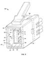
- FIG 2 illustrates the electrical connector 10 from a different perspective as Figure 1 .
- the electrical connector 10 includes a plug body 30 having a cavity 32 defined by outer body walls 34 that define a perimeter of the plug body 30.
- the outer body walls 34 extend between a mating end 36 and a terminating end 38 of the plug body 30.
- the cavity 32 extends along a cavity axis 40 from the mating end 36 to a base end 42 of the cavity 32.
- the cavity 32 is open at the mating end 36 for receiving the contact support member 20 (shown in Figure 1 ) of the mating connector 12 when the electrical connector 10 is plugged into the receptacle 18 (shown in Figure 1 ).
- the electrical connector 10 and the mating connector 12 are co-nested with one another when mated.
- the receptacles 18 of the mating connector 12 surround a perimeter of the outer body walls 34, and the outer body walls surround a perimeter of the contact support member 20.
- the electrical connector 10 is received within the mating connector 12 and at least a portion of the mating connector 12 is received within the electrical connector 10.
- the electrical connector 10 includes a web portion 44 within the cavity 32.
- the web portion 44 extends from the base end 42 of the cavity 32 generally along the cavity axis 40.
- the web portion 44 may be coincident with the cavity axis 40.
- the web portion 44 includes a first side 46 and a generally opposed second side 48. Ends 50, 52 extend between the sides 46, 48 such that the web portion 44 has a generally rectangular cross-sectional shape.
- the web portion 44 may have an alternative shape, including non-planar wall surfaces, in alternative embodiments.
- first and second sides 46, 48 are spaced apart from, and generally face, first and second side walls 54, 56, respectively, of the outer body walls 34.
- a first channel 58 is formed between the first side 46 of the web portion 44 and the first side wall 54
- a second channel 60 is formed between the second side 48 of the web portion 44 and the second side wall 56.
- the first and second channels are generally parallel to one another and are adapted to receive the contact support member 20 of the mating connector 12.
- connecting channels 62 extend between, and connect, the first and second channels 58, 60.
- the connecting channels 62 extend between the ends 50 and 52 and the outer body walls 34.
- the cavity 32 defined at least in part by the channels 58, 60, 62 completely surrounds the web portion 44 along the cavity axis 40.
- the web portion 44 may extend from at least one of the outer body walls 34, such as one of the outer body walls 34 connecting the first and second side walls 54, 56, such that the cavity 32 only includes one connecting channel 62, or alternatively, no connecting channels 62.
- the channels 58, 60 and 62 cooperate to define a mating interface that is adapted to receive the contact support member 20 of the mating connector 12.
- the contacts 24 are provided within the cavity 32 for interfacing with the mating contacts 22 (shown in Figure 1 ) of the mating connector 12.
- the contacts 24 are arranged on the web portion 44.
- the contacts 24 extend between a mating end 70 and a termination end 72 (shown in Figure 3 ) proximate the terminating end 38 of the plug body 30.
- the mating end 70 is exposed within the cavity 38 for engaging the mating contacts 22.
- the contacts 24 are arranged as differential pairs, wherein the contacts 24 of a respective differential pair are aligned with, and substantially co-planar with one another. In the illustrated embodiment, four differential pairs are provided, having two differential pairs on each of the sides 46, 48 of the web portion 44.
- a first differential pair and a second differential pair are arranged on the first side 46, and the contacts 22 of the first and second differential pairs are substantially aligned with one another along a first plane.
- a third differential pair and a fourth differential pair are arranged on the second side 48, and the contacts 22 of the third and fourth differential pairs are substantially aligned with one another along a second plane that is non-coplanar with the first plane.
- the first and second planes may be substantially parallel with, and spaced apart from, one another.
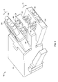
- Figure 3 is a rear view of the electrical connector 10 in an unassembled state illustrating wires 80 positioned for mating with the contacts 24 of the electrical connector 10.
- Figure 4 is a rear view of the electrical connector 10 in an assembled state illustrating the wires 80 mated with the contacts 24 of the electrical connector 10.
- Figure 3 illustrates four discrete wires 80 loaded into wire receiving ports 82 of the plug housing 30, while Figure 4 illustrates eight wires 80 loaded into the wire receiving ports 82.
- the wire receiving ports 82 are provided on hinged wire receiving elements 84 that form part of, or are coupled to, the plug body 30.
- the wire receiving elements 84 are movable between an unmated position, such as the position illustrated in Figure 3 , and a mated position, such as the position illustrated in Figure 4 .
- the wire receiving elements 84 are rotated outward from the plug body 30, such as in the direction of arrow A, to a position in which the wires 80 may be inserted into the wire receiving ports 82.
- the wire receiving elements 84 are rotated generally toward the plug body 30, such as in the direction of arrow B, to a position in which the wires 80 may be terminated to the contacts 24.
- the wires 80 are loaded into the wire receiving ports 82 and then the wire receiving elements 84 are moved to the mated position.
- the wires 80 may be terminated to the contacts 24.
- the wire receiving elements 84 may be separately provided from the plug body 30 and then mounted to the plug body 30.
- the termination ends 72 of the contacts 24 include insulation displacement contact (IDC) terminals 86 extending therefrom.
- IDC terminals 86 may extend generally outward from a contact support member 88 of the plug body 30.
- some of the contacts 24 may extend along a first side 90 of the contact support member 88 and some of the contacts 24 may extend along a second side 92 of the contact support member 88.
- the first and second sides 90, 92 may be substantially aligned with the first and second sides 46, 48 (shown in Figure 1 ) of the web portion 44 (shown in Figure 1 ) such that each contact 24 is substantially linear along its length from the mating end 70 to the termination end 72.
- the IDC terminals 86 may extend generally rearward from the termination ends 72 of the contacts 24, such as in a direction along the contacts 24.
- the wire termination ends 72 may be terminated to the wires 80 using other types of connections or methods, such as soldering, crimping, and the like.
- the wires 80 may also be indirectly connected to the contacts 24, such as by a circuit board, wherein the contacts 24 are connected to the circuit board, the wires 80 are connected to the circuit board, and traces along the circuit board are used to interconnect the wires 80 and the contacts 24.
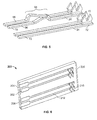
- Figure 5 illustrates two pairs of contacts 24 for the electrical connector and formed in accordance with an exemplary embodiment.
- the two pairs of contacts 24 may be arranged on one of the first or second sides 46, 48 of the web portion 44 (shown in Figure 2 ).
- One of the pairs of contacts 24 includes a cross-over section 94, while the other pair of contacts 24 extend linearly between the mating end 70 and the termination end 72.
- the cross-over section 94 may be used to control the intra-pair electrical interactions between the contacts within the differential pair, and/or the cross-over section 94 may be used to control the inter-pair electrical interaction between contacts of adjacent differential pairs.
- both pairs of contacts 24 may include cross-over sections 94, or alternatively, neither of the pairs of contacts 24 may include a cross-over section 94.
- a first contact 96 represents an inner contact (as compared to the adjacent differential pair) proximate the mating end 70, but then represents an outer contact (as compared to the adjacent differential pair) proximate the termination end 72.
- a second contact 98 represents an inner contact (as compared to the adjacent differential pair) proximate the termination end 72, but then represents an outer contact (as compared to the adjacent differential pair) proximate the mating end 70.
- at least one of the contacts 24 may be non-planar to create the cross-over section 94, however, the contacts remain generally planar along the majority of the length of the contacts 24.
- the contacts 24 may also be generally co-planar with the adjacent pair of contacts 24.
- the differential pairs may include contacts having the cross-over sections 94.
- two of the differential pairs such as differential pairs that are not on the same side of the web portion 44 (shown in Figure 1 ) and that are not aligned across the web portion 44 from one another, may include cross-over sections 94, while the other two differential pairs do not include cross-over sections 94, but rather are passed straight through the plug body 30 from the mating end 70 to the termination end 72.
- Figure 6 illustrates a circuit board 200 that may be received within a plug body of an alternative electrical connector.
- the circuit board 200 includes a plurality of contacts 202 extending between a mating end 204 and a terminating end 206 of the circuit board 200.
- the circuit board 200 and contacts 202 may replace the individual contacts 24 (shown in Figure 2 ) and web portion 44 (shown in Figure 2 ) of the electrical connector 10 (shown in Figure 1 ).
- the circuit board 200 may define a web portion having contacts thereon.
- the contacts 202 include contact pads 208 at the mating end 204 and IDC 210 at the terminating end 206. Traces 212 extend between the contact pads 208 and the IDC 210. Optionally, the traces 212 may be routed in predetermined patterns to provide electrical compensation, or to control the electrical characteristics and/or interactions between and among each of the contacts 202.
- the IDC 210 may be terminated to the circuit board 200 by mounting within through holes in the circuit board 200, by surface mounting, such as by soldering, and the like. In an alternative embodiment, the circuit board 200 may have alternative termination contacts at the terminating end 206 rather than the IDC 210, such as contact pads, crimp contacts, and the like.
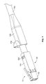
- Figure 7 illustrates a strain relief 100 and boot shroud 102 that may be used with the electrical connector 10.
- the strain relief 100 may be coupled to the terminating end 38 of the plug body 30.
- the strain relief 100 also includes a crimp section 104 that is securely coupled to a cable 106 having the wires 80 (shown in Figures 3 and 4 ).
- the boot shroud 102 may cover at least a portion of the strain relief 100 and the plug body 30.
- the boot shroud 102 includes a hood 110 that covers at least a portion of the latch 26.
- the strain relief 100 may define a shield that is mechanically and electrically connected to a shield of the cable 106.
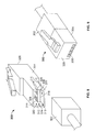
- Figures 8 and 9 are front and rear perspective views of another electrical connector 300 formed in accordance with a further alternative embodiment.
- a mating connector 302 may be interconnected with the electrical connector 300, such as illustrated in Figure 9 .
- the electrical connector 300 includes a plug body 304 and a web portion 306 having a plurality of first mating contacts 308 for mating with the mating connector 302.
- the electrical connector 300 represents a plug connector having a cavity 310 that receives at least a portion of the mating connector 302.
- the plug body 304 includes outer body walls 312 defining an outer perimeter of the plug body 304.
- the outer perimeter of the plug body 304 defines a mating interface that is received within a receptacle of the mating connector 302.
- the web portion 306 is provided within the cavity 310.
- the web portion 306 includes opposed sides 316, 318 and extends from one of the outer body walls 312.
- First and second channels 320, 322 and a connecting channel 324 are formed between the web portion 306 and the outer body walls 312.
- the channels 320, 322, 324 define a space sized and shaped to accept a portion of the mating connector therein.
- the first mating contacts 308 extend along the first and second sides 316, 318 of the web portion 306 such that the first mating contacts 308 face, and are exposed to, respective ones of the channels 320, 322.
- the plug body 304 extends between a first mating end 326 and a second mating end 328.
- the electrical connector 300 defines a plug connector at the first mating end 326 for connection with a receptacle-type mating connector 302.
- the first mating end 326 and the mating connector 302 have a mating interface defined for use within a first wiring system, wherein plugs and receptacles within the first wiring system have a mating interface similar to that shown in Figures 8 and 9 .
- the electrical connector 300 defines a plug type connector at the second mating end 328 for mating with a corresponding receptacle type of connector (not shown).
- the second mating end 328 and the corresponding connector have a mating interface defined for use within a second wiring system, wherein plugs and receptacles within the second wiring system have a mating interface similar to that shown in Figures 8 and 9 .
- the mating interface defined at the second mating end 328 is different than the mating interface at the first mating end 326, such that the second mating end 328 could not be plugged into the mating connector 302.
- the electrical connector 300 may be used as an adaptor for interconnecting components or cables from the first wiring system with components or cables from the second wiring system.
- the second mating end 328 represents an 8P8C modular connector, such as an RJ-45 plug or other type of connector used within a network cabling system.
- the second mating end 328 includes second mating contacts 330. In the illustrated embodiment, eight second mating contacts 330 are provided and the second mating contacts 330 are arranged in a single row.
- the first mating contacts 308 are electrically connected with the second mating contacts 330, which are both arranged as differential signal pairs of contacts.
- both the first and second contacts 308, 330 are integrally formed with one another such that the contacts are exposed at both the first and second mating ends 326, 328. Compensation may be provided by controlling the positions of the contacts with respect to one another between the first and second mating ends 326, 328.
- the first and second mating contacts 308, 330 are interconnected by a circuit board (not shown) that is received within the plug body 304. Additionally, the circuit board may provide electrical compensation for controlling the electrical characteristics of the signal pairs. For example, the electrical characteristics may be matched to particular standards that govern the first and second wiring system.
- Figures 10 and 11 are front and rear perspective views of another electrical connector 400 formed in accordance with another alternative embodiment.
- a mating connector 402 may be coupled to the electrical connector 400.
- the electrical connector 400 includes a plug body 404 and a web portion 406 having a plurality of first mating contacts 408 for mating with the mating connector 402.
- the electrical connector 400 represents a receptacle connector having a cavity 410 that receives the mating connector.
- the plug body 404 includes outer body walls 412 defining an outer perimeter of the plug body 404.
- the outer perimeter of the plug body 404 defines a mating interface that is received within a receptacle of the mating connector 402.
- the web portion 406 is provided within the cavity 410.
- the web portion 406 includes opposed sides 416, 418 and extends between two of the outer body walls 412.
- First and second channels 420, 422 are formed between the web portion 406 and the outer body walls 412.
- the channels 420, 422 define a space sized and shaped to accept a portion of the mating connector therein.
- the first mating contacts 408 extend along the first and second sides 416, 418 of the web portion 406 such that the first mating contacts 408 face, and are exposed to, respective ones of the channels 420, 422.
- the plug body 404 extends between a first mating end 426 and a second mating end 428.
- the electrical connector 400 defines a plug connector at the first mating end 426 for connection with a receptacle-type mating connector 402.
- the first mating end 426 and the mating connector 402 have a mating interface defined for use within a first wiring system, wherein plugs and receptacles within the first wiring system have a mating interface similar to that shown in Figures 10 and 11 .
- the electrical connector 400 defines a receptacle type connector at the second mating end 428 for mating with a corresponding plug type of connector (not shown).
- the second mating end 428 and the corresponding connector have a mating interface defined for use within a second wiring system, wherein plugs and receptacles within the second wiring system have a mating interface similar to that shown in Figures 10 and 11 .
- the mating interface defined at the second mating end 428 is different than the mating interface at the first mating end 426, such that the second mating end 428 could not receive a plug connector having a mating interface of the type at the first mating end 322.
- the electrical connector 400 may be used as an adaptor for interconnecting components or cables from the first wiring system with components or cables from the second wiring system.
- the second mating end 428 represents an 8P8C modular connector, such as an RJ-45 jack or other type of connector used within a network cabling system.
- the second mating end 428 includes second mating contacts 430. In the illustrated embodiment, eight second mating contacts 430 are provided and the second mating contacts 430 are arranged in a single row.
- the first mating contacts 408 are electrically connected with the second mating contacts 430, which are both arranged as differential signal pairs of contacts.
- both the first and second contacts 408, 430 are integrally formed with one another such that the contacts are exposed at both the first and second mating ends 426, 428. Compensation may be provided by controlling the positions of the contacts with respect to one another between the first and second mating ends 426, 428.
- the first and second mating contacts 408, 430 are interconnected by a circuit board (not shown) that is received within the plug body 404. Additionally, the circuit board may provide electrical compensation for controlling the electrical characteristics of the signal pairs. For example, the electrical characteristics may be matched to particular standards that govern the first and second wiring system.
Landscapes
- Details Of Connecting Devices For Male And Female Coupling (AREA)
Applications Claiming Priority (1)
| Application Number | Priority Date | Filing Date | Title |
|---|---|---|---|
| US11/869,553 US7727025B2 (en) | 2007-10-09 | 2007-10-09 | Modular electrical connector with enhanced plug interface |
Publications (2)
| Publication Number | Publication Date |
|---|---|
| EP2048747A2 true EP2048747A2 (de) | 2009-04-15 |
| EP2048747A3 EP2048747A3 (de) | 2011-01-19 |
Family
ID=40227777
Family Applications (1)
| Application Number | Title | Priority Date | Filing Date |
|---|---|---|---|
| EP08166121A Withdrawn EP2048747A3 (de) | 2007-10-09 | 2008-10-08 | Elektrischer Modularsteckverbinder mit erweiterter Steckschnittstelle |
Country Status (4)
| Country | Link |
|---|---|
| US (1) | US7727025B2 (de) |
| EP (1) | EP2048747A3 (de) |
| CN (1) | CN101409412B (de) |
| TW (1) | TWI424637B (de) |
Families Citing this family (22)
| Publication number | Priority date | Publication date | Assignee | Title |
|---|---|---|---|---|
| DE102010014295A1 (de) * | 2010-04-08 | 2011-10-13 | Phoenix Contact Gmbh & Co. Kg | Steckverbinder zur Aufnahme eines mehradrigen Kabels |
| US7967614B1 (en) * | 2010-04-28 | 2011-06-28 | Tyco Electronics Corporation | Plug connector and connector assembly having a pluggable board substrate |
| US8419444B2 (en) * | 2010-09-16 | 2013-04-16 | Mellanox Technologies Ltd. | Adapter for high-speed ethernet |
| US8647146B2 (en) | 2011-01-20 | 2014-02-11 | Tyco Electronics Corporation | Electrical connector having crosstalk compensation insert |
| US8591248B2 (en) | 2011-01-20 | 2013-11-26 | Tyco Electronics Corporation | Electrical connector with terminal array |
| US9033725B2 (en) * | 2012-04-19 | 2015-05-19 | Panduit Corp. | GG45 plug with hinging load bar |
| US8968031B2 (en) | 2012-06-10 | 2015-03-03 | Apple Inc. | Dual connector having ground planes in tongues |
| CN103579798B (zh) * | 2012-08-07 | 2016-08-03 | 泰科电子(上海)有限公司 | 电连接器及其导电端子组件 |
| CN105431982B (zh) | 2013-07-29 | 2019-07-09 | Fci连接器新加坡私人有限公司 | 模块化插孔连接器和端子模块 |
| WO2015137396A1 (ja) * | 2014-03-14 | 2015-09-17 | シャープ株式会社 | 光拡散部材、光拡散部材作製用母材、これを用いた表示装置、および光拡散部材の製造方法 |
| US10644472B2 (en) | 2017-06-28 | 2020-05-05 | Mellanox Technologies, Ltd. | Cable adapter |
| US10128627B1 (en) | 2017-06-28 | 2018-11-13 | Mellanox Technologies, Ltd. | Cable adapter |
| US10705309B2 (en) | 2018-06-06 | 2020-07-07 | Mellanox Technologies, Ltd. | RF EMI reducing fiber cable assembly |
| US10444453B1 (en) | 2018-07-25 | 2019-10-15 | Mellanox Technologies, Ltd. | QSFP-DD to SFP-DD adapter |
| US10741954B1 (en) | 2019-03-17 | 2020-08-11 | Mellanox Technologies, Ltd. | Multi-form-factor connector |
| US11169330B2 (en) | 2019-10-24 | 2021-11-09 | Mellanox Technologies Tlv Ltd. | Wavelength-splitting optical cable |
| CN111180966B (zh) | 2020-01-15 | 2021-10-22 | 东莞立讯技术有限公司 | 插头连接器 |
| CN111224260A (zh) | 2020-01-15 | 2020-06-02 | 东莞立讯技术有限公司 | 插座连接器及连接器组合 |
| WO2022006549A1 (en) * | 2020-07-02 | 2022-01-06 | Commscope Technologies Llc | Telecommunications jack adapter |
| US12456845B1 (en) | 2020-07-02 | 2025-10-28 | Commscope Technologies Llc | Universal jack opening |
| US11929568B2 (en) * | 2020-09-24 | 2024-03-12 | Avx Corporation | Solderless wire-to-board single pair ethernet connection system |
| DE112022003936T5 (de) | 2021-09-23 | 2024-06-20 | KYOCERA AVX Components Corporation | Draht-Zu-Draht-Anschlussverbinder |
Family Cites Families (26)
| Publication number | Priority date | Publication date | Assignee | Title |
|---|---|---|---|---|
| US3760335A (en) * | 1971-05-27 | 1973-09-18 | Amp Inc | Pre-loaded electric connector |
| US5197901A (en) * | 1990-10-30 | 1993-03-30 | Japan Aviation Electronics Industry, Limited | Lock-spring and lock-equipped connector |
| US5342216A (en) * | 1992-10-01 | 1994-08-30 | The Whitaker Corporation | Jackscrew mechanism |
| US5273459A (en) * | 1992-10-01 | 1993-12-28 | The Whitaker Corporation | Connector feature for improved contact wiping |
| US5409400A (en) * | 1993-01-15 | 1995-04-25 | The Whitaker Corporation | Shielding for an electrical connector |
| US5340333A (en) * | 1993-01-15 | 1994-08-23 | Interconnect Systems Group Inc. | Shielded modular adapter |
| USD367039S (en) * | 1994-05-10 | 1996-02-13 | PK Electronic Industries SDN BHD | Network adaptor |
| US5462457A (en) | 1994-09-22 | 1995-10-31 | The Whitaker Corporation | Overmold strain relief and snag prevention feature |
| JP3171807B2 (ja) * | 1997-01-24 | 2001-06-04 | 東京エレクトロン株式会社 | 洗浄装置及び洗浄方法 |
| US6328601B1 (en) * | 1998-01-15 | 2001-12-11 | The Siemon Company | Enhanced performance telecommunications connector |
| US6120329A (en) | 1998-05-08 | 2000-09-19 | The Whitaker Corporation | Modular jack with anti-cross-talk contacts and method of making same |
| DE19822630C1 (de) * | 1998-05-20 | 2000-09-07 | Krone Gmbh | Anordnung von Kontaktpaaren zur Kompensation des Nahnebensprechens für eine elektrische Steckverbindung |
| US5947761A (en) | 1998-09-29 | 1999-09-07 | The Whitaker Corporation | Electrical connector with pivoting wire fixture |
| US6270381B1 (en) * | 2000-07-07 | 2001-08-07 | Avaya Technology Corp. | Crosstalk compensation for electrical connectors |
| US6273740B1 (en) * | 2000-07-21 | 2001-08-14 | Mobility Electronics Inc. | Quick release spring connector adaptor for a computer cable |
| JP3564555B2 (ja) * | 2001-03-05 | 2004-09-15 | 日本航空電子工業株式会社 | 高速ディファレンシャル信号伝送用コネクタ |
| US6511344B2 (en) * | 2001-07-02 | 2003-01-28 | Fci Americas Technology, Inc. | Double-deck electrical connector with cross-talk compensation |
| US6655988B1 (en) | 2003-01-13 | 2003-12-02 | Tyco Electronics Corporation | Multi-port modular jack assembly with LED indicators |
| US6887091B1 (en) * | 2003-12-24 | 2005-05-03 | Hon Hai Precision Ind. Co., Ltd. | Cable connector assembly having additional pull tab |
| US7048550B2 (en) | 2004-06-18 | 2006-05-23 | Hon Hai Precision Ind. Co., Ltd. | Electrical adapter assembly |
| JP4494251B2 (ja) * | 2004-07-26 | 2010-06-30 | 富士通コンポーネント株式会社 | 平衡伝送用コネクタユニット |
| US7207807B2 (en) | 2004-12-02 | 2007-04-24 | Tyco Electronics Corporation | Noise canceling differential connector and footprint |
| US7195518B2 (en) | 2005-05-02 | 2007-03-27 | Tyco Electronics Corporation | Electrical connector with enhanced jack interface |
| CN2838071Y (zh) * | 2005-07-14 | 2006-11-15 | 连展科技(深圳)有限公司 | 改良介面的电连接器总成 |
| JP4360364B2 (ja) * | 2005-08-26 | 2009-11-11 | パナソニック電工株式会社 | コネクタ |
| CN200941504Y (zh) * | 2006-08-08 | 2007-08-29 | 富士康(昆山)电脑接插件有限公司 | 插座连接器 |
-
2007
- 2007-10-09 US US11/869,553 patent/US7727025B2/en active Active
-
2008
- 2008-10-03 TW TW097138150A patent/TWI424637B/zh active
- 2008-10-08 EP EP08166121A patent/EP2048747A3/de not_active Withdrawn
- 2008-10-09 CN CN200810179975.XA patent/CN101409412B/zh active Active
Non-Patent Citations (1)
| Title |
|---|
| None |
Also Published As
| Publication number | Publication date |
|---|---|
| US20090093166A1 (en) | 2009-04-09 |
| TWI424637B (zh) | 2014-01-21 |
| US7727025B2 (en) | 2010-06-01 |
| TW200934014A (en) | 2009-08-01 |
| CN101409412A (zh) | 2009-04-15 |
| CN101409412B (zh) | 2012-08-29 |
| EP2048747A3 (de) | 2011-01-19 |
Similar Documents
| Publication | Publication Date | Title |
|---|---|---|
| US7727025B2 (en) | Modular electrical connector with enhanced plug interface | |
| EP2048742B1 (de) | Elektrischer Modularsteckverbinder mit erweiterter Buchsenschnittstelle | |
| CN103107438B (zh) | 与电信插口配合的电信插头 | |
| US7404739B2 (en) | Electrical connector with enhanced jack interface | |
| US7572148B1 (en) | Coupler for interconnecting electrical connectors | |
| KR101038375B1 (ko) | 크로스토크를 최적화하는 콘택 어레이를 갖는 리셉터클 | |
| CN102484343B (zh) | 具有可分离的触头的电连接器 | |
| TW201904147A (zh) | 電連接器系統 | |
| US7575482B1 (en) | Electrical connector with enhanced back end design | |
| EP2939314B1 (de) | Schnittstellenadapter | |
| US20090149075A1 (en) | Distribution module for converting between symmetrical and asymmetrical data transmission paths | |
| CN102754287B (zh) | 用于无缆线插接装置的模块式连接器 | |
| GB2428337A (en) | Enhanced jack with plug engaging printed circuit board | |
| HK1115479B (en) | Electrical connector with shielded differential contact pairs |
Legal Events
| Date | Code | Title | Description |
|---|---|---|---|
| PUAI | Public reference made under article 153(3) epc to a published international application that has entered the european phase |
Free format text: ORIGINAL CODE: 0009012 |
|
| AK | Designated contracting states |
Kind code of ref document: A2 Designated state(s): AT BE BG CH CY CZ DE DK EE ES FI FR GB GR HR HU IE IS IT LI LT LU LV MC MT NL NO PL PT RO SE SI SK TR |
|
| AX | Request for extension of the european patent |
Extension state: AL BA MK RS |
|
| PUAL | Search report despatched |
Free format text: ORIGINAL CODE: 0009013 |
|
| AK | Designated contracting states |
Kind code of ref document: A3 Designated state(s): AT BE BG CH CY CZ DE DK EE ES FI FR GB GR HR HU IE IS IT LI LT LU LV MC MT NL NO PL PT RO SE SI SK TR |
|
| AX | Request for extension of the european patent |
Extension state: AL BA MK RS |
|
| 17P | Request for examination filed |
Effective date: 20110704 |
|
| AKX | Designation fees paid |
Designated state(s): DE FR GB |
|
| RIC1 | Information provided on ipc code assigned before grant |
Ipc: H01R 13/6461 20110101AFI20130110BHEP Ipc: H01R 24/64 20110101ALI20130110BHEP |
|
| 17Q | First examination report despatched |
Effective date: 20130130 |
|
| STAA | Information on the status of an ep patent application or granted ep patent |
Free format text: STATUS: THE APPLICATION IS DEEMED TO BE WITHDRAWN |
|
| 18D | Application deemed to be withdrawn |
Effective date: 20130620 |