EP2048767A2 - Système de contrôle - Google Patents
Système de contrôle Download PDFInfo
- Publication number
- EP2048767A2 EP2048767A2 EP08165474A EP08165474A EP2048767A2 EP 2048767 A2 EP2048767 A2 EP 2048767A2 EP 08165474 A EP08165474 A EP 08165474A EP 08165474 A EP08165474 A EP 08165474A EP 2048767 A2 EP2048767 A2 EP 2048767A2
- Authority
- EP
- European Patent Office
- Prior art keywords
- control unit
- contacting device
- electric motor
- contacting
- control device
- Prior art date
- Legal status (The legal status is an assumption and is not a legal conclusion. Google has not performed a legal analysis and makes no representation as to the accuracy of the status listed.)
- Withdrawn
Links
- 230000005540 biological transmission Effects 0.000 claims description 2
- 238000006073 displacement reaction Methods 0.000 claims description 2
- 238000009413 insulation Methods 0.000 claims description 2
- 238000009434 installation Methods 0.000 description 7
- 230000002349 favourable effect Effects 0.000 description 2
Images

Classifications
-
- H—ELECTRICITY
- H02—GENERATION; CONVERSION OR DISTRIBUTION OF ELECTRIC POWER
- H02K—DYNAMO-ELECTRIC MACHINES
- H02K5/00—Casings; Enclosures; Supports
- H02K5/04—Casings or enclosures characterised by the shape, form or construction thereof
- H02K5/22—Auxiliary parts of casings not covered by groups H02K5/06-H02K5/20, e.g. shaped to form connection boxes or terminal boxes
- H02K5/225—Terminal boxes or connection arrangements
-
- H—ELECTRICITY
- H02—GENERATION; CONVERSION OR DISTRIBUTION OF ELECTRIC POWER
- H02K—DYNAMO-ELECTRIC MACHINES
- H02K11/00—Structural association of dynamo-electric machines with electric components or with devices for shielding, monitoring or protection
- H02K11/20—Structural association of dynamo-electric machines with electric components or with devices for shielding, monitoring or protection for measuring, monitoring, testing, protecting or switching
- H02K11/21—Devices for sensing speed or position, or actuated thereby
-
- H—ELECTRICITY
- H02—GENERATION; CONVERSION OR DISTRIBUTION OF ELECTRIC POWER
- H02K—DYNAMO-ELECTRIC MACHINES
- H02K11/00—Structural association of dynamo-electric machines with electric components or with devices for shielding, monitoring or protection
- H02K11/30—Structural association with control circuits or drive circuits
- H02K11/33—Drive circuits, e.g. power electronics
-
- H—ELECTRICITY
- H02—GENERATION; CONVERSION OR DISTRIBUTION OF ELECTRIC POWER
- H02K—DYNAMO-ELECTRIC MACHINES
- H02K2211/00—Specific aspects not provided for in the other groups of this subclass relating to measuring or protective devices or electric components
- H02K2211/03—Machines characterised by circuit boards, e.g. pcb
Definitions
- the invention relates to a control device, in particular for a steering with electric power assistance, which is arranged at a certain location on an outer shell of an electric motor.
- the invention has the object to improve a control device of the type mentioned in that the electrical connection between the control unit and the electric motor is as simple as possible and the arrangement of the control unit and electric motor requires the smallest possible installation space.
- the invention solves this problem by a control unit of the type mentioned, in which according to the invention, the control unit and the electric motor by means of a provided on a front side of the electric motor contacting device is electrically connected.
- the contacting device leaves Easy, fast and inexpensive to assemble. In addition, it can be arranged to save space on the outer shell of the electric motor with it, so that the requirements for a small installation space are met by the contacting device. Since the contacting device allows the closest possible connection of the control unit to the electric motor, a particularly high electromagnetic compatibility is ensured by the contacting device.
- the contacting device can also be arranged on an end face of the control unit.
- the contacting device can have detachably fastenable plug connections and / or insulation displacement contacts.
- the contacting device may comprise a printed circuit board.
- the printed circuit board may be flexible, so that one and the same circuit board can be adapted to different installation situations or a common circuit board for the control unit and the contacting device is used. An expensive storage of printed circuit boards with different shape can therefore be omitted.
- the contacting device can be produced very inexpensively in large numbers if it has a stamped and bent part.
- the contacting device has electrical lines.
- the contacting device may optionally have a sensor for detecting a rotation angle and / or for detecting a rotational speed of the electric motor.
- the contacting device may have an electrical component for power transmission having power electronics. This reduces the power loss and saves separate components that would have to be provided in addition to the contacting device or the control unit.
- the invention further relates to a steering, in particular for a motor vehicle, which is equipped according to the invention with a control device according to one of claims 1 to 11.
- Fig. 1 shows a control unit 10 which is electrically connected by means of a contacting device 11 with an electric motor 12.
- the contacting device 11 is arranged both on an end face of the electric motor 12 and on an end face of the control unit 10.
- a control unit 20 and an electric motor 21 are interconnected by a contacting device 22 designed as a flexible printed circuit board (see Fig. 2 ).
- the contacting device 22 is thus flexibly adaptable to different installation situations.
- the contacting device 22 expediently connects the control unit 20 to a printed circuit board 23 of the electric motor 21.
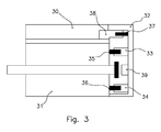
- Fig. 3 shows a control unit 30 and an electric motor 31, which are electrically connected to each other by means of a contacting device 32.
- the contacting device 32 has plug connections 33 and 34, which are on motor-side connectors 35 and 36 are plugged. As a result, the contacting device 32 can be electrically connected to the electric motor 31 very quickly and easily.
- the contacting device 32 has a plug-in connection 37 which is plugged onto a plug-in connection 38 on the control unit side. This allows a quick and easy electrical connection between the contacting device 32 and the control unit 30.
Landscapes
- Engineering & Computer Science (AREA)
- Power Engineering (AREA)
- Microelectronics & Electronic Packaging (AREA)
- Power Steering Mechanism (AREA)
Applications Claiming Priority (1)
| Application Number | Priority Date | Filing Date | Title |
|---|---|---|---|
| DE102007000961A DE102007000961A1 (de) | 2007-10-08 | 2007-10-08 | Steuergerät |
Publications (1)
| Publication Number | Publication Date |
|---|---|
| EP2048767A2 true EP2048767A2 (fr) | 2009-04-15 |
Family
ID=39928488
Family Applications (1)
| Application Number | Title | Priority Date | Filing Date |
|---|---|---|---|
| EP08165474A Withdrawn EP2048767A2 (fr) | 2007-10-08 | 2008-09-30 | Système de contrôle |
Country Status (2)
| Country | Link |
|---|---|
| EP (1) | EP2048767A2 (fr) |
| DE (1) | DE102007000961A1 (fr) |
Cited By (5)
| Publication number | Priority date | Publication date | Assignee | Title |
|---|---|---|---|---|
| EP2607709A1 (fr) * | 2011-12-23 | 2013-06-26 | Grundfos Holding A/S | Moteur électrique |
| EP2607708A1 (fr) * | 2011-12-23 | 2013-06-26 | Grundfos Holding A/S | Moteur électrique |
| EP2607707A1 (fr) * | 2011-12-23 | 2013-06-26 | Grundfos Holding A/S | Moteur électrique |
| DE102018201206A1 (de) * | 2018-01-26 | 2019-08-01 | Siemens Aktiengesellschaft | Modulare Anordnung eines Umrichters und Luftfahrzeug mit einer derartigen Anordnung |
| WO2019161837A1 (fr) * | 2018-02-21 | 2019-08-29 | Schaeffler Technologies AG & Co. KG | Contrôleur pour un moteur électrique et actionneur |
-
2007
- 2007-10-08 DE DE102007000961A patent/DE102007000961A1/de not_active Withdrawn
-
2008
- 2008-09-30 EP EP08165474A patent/EP2048767A2/fr not_active Withdrawn
Cited By (10)
| Publication number | Priority date | Publication date | Assignee | Title |
|---|---|---|---|---|
| EP2607709A1 (fr) * | 2011-12-23 | 2013-06-26 | Grundfos Holding A/S | Moteur électrique |
| EP2607708A1 (fr) * | 2011-12-23 | 2013-06-26 | Grundfos Holding A/S | Moteur électrique |
| EP2607707A1 (fr) * | 2011-12-23 | 2013-06-26 | Grundfos Holding A/S | Moteur électrique |
| WO2013092917A1 (fr) * | 2011-12-23 | 2013-06-27 | Grundfos Holding A/S | Moteur électrique |
| WO2013092534A1 (fr) * | 2011-12-23 | 2013-06-27 | Grundfos Holding A/S | Moteur électrique |
| WO2013092317A3 (fr) * | 2011-12-23 | 2014-06-12 | Grundfos Holding A/S | Moteur électrique |
| US9467019B2 (en) | 2011-12-23 | 2016-10-11 | Grundfos Holding A/S | Electric motor |
| DE102018201206A1 (de) * | 2018-01-26 | 2019-08-01 | Siemens Aktiengesellschaft | Modulare Anordnung eines Umrichters und Luftfahrzeug mit einer derartigen Anordnung |
| US11539305B2 (en) | 2018-01-26 | 2022-12-27 | Rolls-Royce Deutschland Ltd & Co Kg | Modular arrangement of a converter and aircraft having a modular arrangement |
| WO2019161837A1 (fr) * | 2018-02-21 | 2019-08-29 | Schaeffler Technologies AG & Co. KG | Contrôleur pour un moteur électrique et actionneur |
Also Published As
| Publication number | Publication date |
|---|---|
| DE102007000961A1 (de) | 2009-05-07 |
Similar Documents
| Publication | Publication Date | Title |
|---|---|---|
| EP2592914B1 (fr) | Elément de serrage | |
| DE102013209315B4 (de) | Steuereinrichtung und mit einer Steuereinrichtung integrierte elektrische Rotationsmaschine | |
| DE112015004262B4 (de) | Elektronische Steuervorrichtung und elektrische Servolenkungsvorrichtung | |
| DE102017202765A1 (de) | Steuervorrichtung für einen Elektromotor | |
| EP0853022B1 (fr) | Module de fonction pour véhicule. | |
| DE112016002965T5 (de) | Stromdetektiervorrichtung | |
| DE112016006534T5 (de) | Verbindungs-Anschluss-Baugruppe und elektromotorische Antriebsvorrichtung, welche diese verwendet | |
| EP2048767A2 (fr) | Système de contrôle | |
| DE102014212925A1 (de) | Verbindungselement für ein Flachkabel | |
| DE102004050687A1 (de) | Kontaktierung eines Kabels an einer flexiblen Leiterbahn | |
| EP2656452B1 (fr) | Connecteur électrique à borne de contact située en amont | |
| DE10033088B4 (de) | Aufschnappen des Spiegelantriebes | |
| DE10107630B4 (de) | Stiftleiste und Sensorsystem für Kraftfahrzeuge mit derartiger Stiftleiste | |
| WO2012159961A1 (fr) | Élément structural pour une unité enfichable destinée à la connexion de composants électriques et unité enfichable pour un véhicule, en particulier pour un véhicule ferroviaire | |
| DE2722736C2 (de) | Mehrpolige Anschlußleiste | |
| DE102010029374A1 (de) | Leistungselektronikanordnung | |
| DE102006005941A1 (de) | Halter für eine flexible Leiterplatte | |
| DE102022133853A1 (de) | Flexibler Flachleiter und Halteeinrichtung für diesen | |
| EP2076414A1 (fr) | Support de raccordement pour loger une électronique moteur | |
| DE102007058095A1 (de) | Leiterplatte mit daran angeschlossenen Kontaktstiften | |
| DE102017209626A1 (de) | Antriebseinheit mit einem elektronisch kommutierten Motor und einer Elektronikeinheit | |
| EP3577725B1 (fr) | Connecteur enfichable équipé d'un pont de connexion de conducteurs de protection | |
| DE102021209105A1 (de) | Sensoreinrichtung zum Erfassen einer Drehstellung eines Rotors einer elektrischen Maschine, Antriebseinrichtung, Druckerzeuger für eine Bremsanlage | |
| DE102020205579A1 (de) | Elektronische vorrichtung | |
| DE102022103338B4 (de) | Elektrisches Steckverbindungssystem eines Kraftfahrzeugs und Kraftfahrzeug |
Legal Events
| Date | Code | Title | Description |
|---|---|---|---|
| PUAI | Public reference made under article 153(3) epc to a published international application that has entered the european phase |
Free format text: ORIGINAL CODE: 0009012 |
|
| AK | Designated contracting states |
Kind code of ref document: A2 Designated state(s): AT BE BG CH CY CZ DE DK EE ES FI FR GB GR HR HU IE IS IT LI LT LU LV MC MT NL NO PL PT RO SE SI SK TR |
|
| AX | Request for extension of the european patent |
Extension state: AL BA MK RS |
|
| STAA | Information on the status of an ep patent application or granted ep patent |
Free format text: STATUS: THE APPLICATION IS DEEMED TO BE WITHDRAWN |
|
| 18D | Application deemed to be withdrawn |
Effective date: 20120403 |