EP2048873A1 - Bildsignalprozessor und Verfahren dafür - Google Patents
Bildsignalprozessor und Verfahren dafür Download PDFInfo
- Publication number
- EP2048873A1 EP2048873A1 EP08162072A EP08162072A EP2048873A1 EP 2048873 A1 EP2048873 A1 EP 2048873A1 EP 08162072 A EP08162072 A EP 08162072A EP 08162072 A EP08162072 A EP 08162072A EP 2048873 A1 EP2048873 A1 EP 2048873A1
- Authority
- EP
- European Patent Office
- Prior art keywords
- image signal
- subfields
- pattern
- group
- frame
- Prior art date
- Legal status (The legal status is an assumption and is not a legal conclusion. Google has not performed a legal analysis and makes no representation as to the accuracy of the status listed.)
- Ceased
Links
Images


Classifications
-
- H—ELECTRICITY
- H04—ELECTRIC COMMUNICATION TECHNIQUE
- H04N—PICTORIAL COMMUNICATION, e.g. TELEVISION
- H04N5/00—Details of television systems
- H04N5/14—Picture signal circuitry for video frequency region
- H04N5/21—Circuitry for suppressing or minimising disturbance, e.g. moiré or halo
-
- G—PHYSICS
- G09—EDUCATION; CRYPTOGRAPHY; DISPLAY; ADVERTISING; SEALS
- G09G—ARRANGEMENTS OR CIRCUITS FOR CONTROL OF INDICATING DEVICES USING STATIC MEANS TO PRESENT VARIABLE INFORMATION
- G09G3/00—Control arrangements or circuits, of interest only in connection with visual indicators other than cathode-ray tubes
- G09G3/20—Control arrangements or circuits, of interest only in connection with visual indicators other than cathode-ray tubes for presentation of an assembly of a number of characters, e.g. a page, by composing the assembly by combination of individual elements arranged in a matrix no fixed position being assigned to or needed to be assigned to the individual characters or partial characters
- G09G3/2007—Display of intermediate tones
- G09G3/2018—Display of intermediate tones by time modulation using two or more time intervals
- G09G3/2022—Display of intermediate tones by time modulation using two or more time intervals using sub-frames
- G09G3/204—Display of intermediate tones by time modulation using two or more time intervals using sub-frames the sub-frames being organized in consecutive sub-frame groups
-
- G—PHYSICS
- G09—EDUCATION; CRYPTOGRAPHY; DISPLAY; ADVERTISING; SEALS
- G09G—ARRANGEMENTS OR CIRCUITS FOR CONTROL OF INDICATING DEVICES USING STATIC MEANS TO PRESENT VARIABLE INFORMATION
- G09G3/00—Control arrangements or circuits, of interest only in connection with visual indicators other than cathode-ray tubes
- G09G3/20—Control arrangements or circuits, of interest only in connection with visual indicators other than cathode-ray tubes for presentation of an assembly of a number of characters, e.g. a page, by composing the assembly by combination of individual elements arranged in a matrix no fixed position being assigned to or needed to be assigned to the individual characters or partial characters
- G09G3/22—Control arrangements or circuits, of interest only in connection with visual indicators other than cathode-ray tubes for presentation of an assembly of a number of characters, e.g. a page, by composing the assembly by combination of individual elements arranged in a matrix no fixed position being assigned to or needed to be assigned to the individual characters or partial characters using controlled light sources
- G09G3/28—Control arrangements or circuits, of interest only in connection with visual indicators other than cathode-ray tubes for presentation of an assembly of a number of characters, e.g. a page, by composing the assembly by combination of individual elements arranged in a matrix no fixed position being assigned to or needed to be assigned to the individual characters or partial characters using controlled light sources using luminous gas-discharge panels, e.g. plasma panels
- G09G3/288—Control arrangements or circuits, of interest only in connection with visual indicators other than cathode-ray tubes for presentation of an assembly of a number of characters, e.g. a page, by composing the assembly by combination of individual elements arranged in a matrix no fixed position being assigned to or needed to be assigned to the individual characters or partial characters using controlled light sources using luminous gas-discharge panels, e.g. plasma panels using AC panels
- G09G3/291—Control arrangements or circuits, of interest only in connection with visual indicators other than cathode-ray tubes for presentation of an assembly of a number of characters, e.g. a page, by composing the assembly by combination of individual elements arranged in a matrix no fixed position being assigned to or needed to be assigned to the individual characters or partial characters using controlled light sources using luminous gas-discharge panels, e.g. plasma panels using AC panels controlling the gas discharge to control a cell condition, e.g. by means of specific pulse shapes
-
- G—PHYSICS
- G09—EDUCATION; CRYPTOGRAPHY; DISPLAY; ADVERTISING; SEALS
- G09G—ARRANGEMENTS OR CIRCUITS FOR CONTROL OF INDICATING DEVICES USING STATIC MEANS TO PRESENT VARIABLE INFORMATION
- G09G3/00—Control arrangements or circuits, of interest only in connection with visual indicators other than cathode-ray tubes
- G09G3/20—Control arrangements or circuits, of interest only in connection with visual indicators other than cathode-ray tubes for presentation of an assembly of a number of characters, e.g. a page, by composing the assembly by combination of individual elements arranged in a matrix no fixed position being assigned to or needed to be assigned to the individual characters or partial characters
- G09G3/22—Control arrangements or circuits, of interest only in connection with visual indicators other than cathode-ray tubes for presentation of an assembly of a number of characters, e.g. a page, by composing the assembly by combination of individual elements arranged in a matrix no fixed position being assigned to or needed to be assigned to the individual characters or partial characters using controlled light sources
- G09G3/28—Control arrangements or circuits, of interest only in connection with visual indicators other than cathode-ray tubes for presentation of an assembly of a number of characters, e.g. a page, by composing the assembly by combination of individual elements arranged in a matrix no fixed position being assigned to or needed to be assigned to the individual characters or partial characters using controlled light sources using luminous gas-discharge panels, e.g. plasma panels
- G09G3/288—Control arrangements or circuits, of interest only in connection with visual indicators other than cathode-ray tubes for presentation of an assembly of a number of characters, e.g. a page, by composing the assembly by combination of individual elements arranged in a matrix no fixed position being assigned to or needed to be assigned to the individual characters or partial characters using controlled light sources using luminous gas-discharge panels, e.g. plasma panels using AC panels
- G09G3/296—Driving circuits for producing the waveforms applied to the driving electrodes
-
- H—ELECTRICITY
- H04—ELECTRIC COMMUNICATION TECHNIQUE
- H04N—PICTORIAL COMMUNICATION, e.g. TELEVISION
- H04N5/00—Details of television systems
- H04N5/14—Picture signal circuitry for video frequency region
- H04N5/142—Edging; Contouring
-
- G—PHYSICS
- G09—EDUCATION; CRYPTOGRAPHY; DISPLAY; ADVERTISING; SEALS
- G09G—ARRANGEMENTS OR CIRCUITS FOR CONTROL OF INDICATING DEVICES USING STATIC MEANS TO PRESENT VARIABLE INFORMATION
- G09G2320/00—Control of display operating conditions
- G09G2320/02—Improving the quality of display appearance
- G09G2320/0261—Improving the quality of display appearance in the context of movement of objects on the screen or movement of the observer relative to the screen
-
- G—PHYSICS
- G09—EDUCATION; CRYPTOGRAPHY; DISPLAY; ADVERTISING; SEALS
- G09G—ARRANGEMENTS OR CIRCUITS FOR CONTROL OF INDICATING DEVICES USING STATIC MEANS TO PRESENT VARIABLE INFORMATION
- G09G2320/00—Control of display operating conditions
- G09G2320/10—Special adaptations of display systems for operation with variable images
- G09G2320/106—Determination of movement vectors or equivalent parameters within the image
Definitions
- Apparatuses and methods consistent with the present invention relate to processing images, and more particularly, to processing a phase alternation by line (PAL) system image signal for a display on a plasma display panel (PDP).
- PAL phase alternation by line
- PDP plasma display panel
- a related art method for displaying a phase alternation by line system image signal on a plasma display panel uses a pseudo 100 Hz driving scheme, or 100 Hz or 75 Hz driving scheme that adopts the frame rate conversion.
- the pseudo 100 Hz driving scheme relates to dividing the subfields (SF1, SF2, ..., SF14) into a first group (SF1, SF2, ..., SF7) and a second group (SF8, SF9, ..., SF14), and causing the first and second groups to illuminate in a similar pattern so that the flicker may be decreased. While the pseudo 100 Hz driving scheme reduces flicker, it produces a double edge phenomenon.
- pixels a, b, c, d, e, f, i, j, ..., p have relatively darker gray values, while pixels g and h have the brighter gray values. Due to a limited range of human eye movement, the pixels g and h are recognized to be in the brightness as illustrated in FIG. 1B , which means a blurry movement occurs in the image.
- the vertical axis represents gray values, and horizontal axis represents the location of the pixels.
- the driving time decreases by half and the number of subfields also decreases. Accordingly, the number of available gray values decreases, requiring more operations such as an error diffusion or dithering. As a result, more severe noise may be generated.
- Exemplary embodiments of the present invention aim to overcome the above problems and/or disadvantages and other disadvantages not described above.
- Exemplary embodiments of the present invention provide an image signal processor and a method thereof for displaying a PAL image signal, capable of improving quality degradation due to flicker and double edge, and preventing noise due to changes in the number of gray values, by moving the location of the illuminating pattern without reducing the number of gray values.
- an image signal processor including: a pattern generating unit which divides subfields of a frame of a received image signal into a first group of subfields and a second group of subfields having a symmetrical pattern with one another, and a pattern moving unit which moves one of the pattern of the first group of subfields and the second group of subfields and outputs the moved pattern.
- the pattern moving unit suitably moves the pattern of the first group subfields in a first direction based on a motion vector of the received image signal.
- the first direction is suitably opposite to the movement direction of a human eye.
- the pattern moving unit suitably moves the pattern of the second group subfields in a second direction based on a motion vector of the received image signal.
- the second direction suitably coincides with the movement direction of a human eye.
- the pattern moving unit suitably moves the pattern of the first group subfields or the second group subfields by a half size of a motion vector of the received image signal.
- the image signal processor may further include a delay unit which delays the received image signal by one frame and outputs the result, and a motion estimation unit which estimates a motion vector between previous and current frames using the pixel values of the previous frame output from the delay unit and the pixel values of the current frame.
- the image signal processor may further include a reverse gamma compensation unit which performs a reverse gamma compensation of the received image signal and provides the pattern generating unit with the result, and a driving unit which drives a PDP to display the image signal in which the pattern is moved by the pattern moving unit.
- a reverse gamma compensation unit which performs a reverse gamma compensation of the received image signal and provides the pattern generating unit with the result
- a driving unit which drives a PDP to display the image signal in which the pattern is moved by the pattern moving unit.
- the image signal processor may be implemented as a broadcast receiving apparatus which receives and processes a red/green/blue (RGB) image included in a PAL system broadcast signal.
- RGB red/green/blue
- an image signal processing method including: dividing subfields of a frame of a received image signal into a first group of subfields and a second group of subfields having a symmetrical pattern with one another; moving the pattern of one of the first group of subfields and the second group of subfields; and outputting the moved pattern.
- the moving may include moving the pattern of the first group subfields in a first direction based on a motion vector of the received image signal.
- the first direction is suitably opposite to the movement direction of a human eye.
- the moving may include moving the pattern of the second group subfields in a second direction based on a motion vector of the received image signal.
- the second direction suitably coincides with the movement direction of human eye.
- the moving may include moving the pattern of the first group subfields or the second group subfields by a half size of a motion vector of the received image signal.
- the image signal processing method may further include delaying the received image signal by one frame and outputting the result, and estimating a motion vector between previous and current frames using the pixel values of the previous and current frames.
- the image signal processing method may further include performing a reverse gamma compensation of the received image signal and providing the result, and driving a PDP to display the image signal in which the pattern is moved.
- the image signal may be implemented as a red/green/blue (RGB) image included in a PAL system broadcast signal.
- RGB red/green/blue
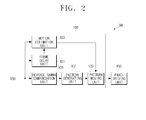
- FIG. 2 is a block diagram of an image signal processor according to an exemplary embodiment of the present invention.
- the image signal processor 98 includes an image signal processing unit 100 and a panel driving unit 150.
- the image signal processing unit 100 processes a received red/green/blue (RGB) image signal for image enhancement, and outputs the result.
- the image signal processing unit 100 includes a frame delay unit 101, a motion estimation unit 103, a reverse gamma compensation unit 105, a pattern generating unit 107, and a pattern moving unit 109.
- the frame delay unit 101 includes a memory to store the received RGB image signal.
- the RGB image signals are delayed by one frame in the frame delay unit 101 and thus are output as the previous frame.
- the motion compensation unit 103 estimates the motion vector between the previous and current frames using the pixel values of the previous and current frames, and outputs the result.
- the reverse gamma compensation unit 105 performs reverse gamma compensation of the RGB image signal and outputs the result.
- the reverse gamma compensation unit 105 compensates the gray values so that the brightness of the received RGB image signal is in a linear relation with the perceived brightness.
- the pattern generating unit 107 divides the subfields of one frame of the RGB image signal into first and second groups which have a symmetrical pattern with each other, and outputs the result.
- the subfields SF1, SF2, ..., SF14 of one frame are divided into a first group including subfields SF1, SF2, ..., SF7, and a second group including subfields SF8, SF9, ..., SF14.
- the patterns are generated and represented in a symmetrical relation with each other between the subfields of the first and second groups.
- the subfields SF1, SF2, ..., SF7 of the first group represent the similar illumination pattern as that of the subfields SF8, SF9, ..., SF14 of the second group.
- the pattern moving unit 109 moves the pattern of the first group subfields SF1, SF2, ..., SF7, or the second group subfields SF8, SF9, ..., SF14 based on the motion vector output from the motion estimation unit 103.
- the pattern of the first group subfields SF1, SF2, ..., SF7 may be moved in a first direction 160 opposite to the movement direction of human eye.
- the pattern of the second group subfields SF8, SF9, ..., SF14 may be moved in a second direction 162 coincidental to (towards) the movement direction of human eye.
- FIG. 3A illustrates human eye moving rightward of the image.
- the pattern moving unit 109 moves the pattern of the first group subfields SF1, SF2, ..., SF7 or the pattern of the second group subfields SF8, SF9, ..., SF14 by a half of the motion vector.
- the motion vector length is six (6) pixels between the previous and current frames.
- the pattern moving unit 109 moves the pattern of the first group subfields SF1, SF2, ..., SF7 by -3 pixels, that is, by three (3) pixels opposite to the movement direction of human eye.
- the pattern moving unit 109 may move the pattern of the second group subfields SF8, SF9, ..., SF14 by +3 pixels, that is, by three (3) pixels coincidental to the movement direction of human eye.
- the physical time may be measured and stored in the pattern moving unit 109 as a fixed value.
- the pattern moving unit 109 moves the pattern of the first group subfields SF1, SF2, ..., SF7 by - 3.6 pixels, that is, by 3.6 pixels opposite to the movement direction of human eye.
- the pattern moving unit 109 may move the pattern of the second group subfields SF8, SF9, ..., SF14 by + 3.6 pixels, that is, by 3.6 pixels coincidental to the movement direction of human eye.
- the pattern moving unit 109 moves the pattern of the first group subfields SF1, SF2, ..., SF7 or the pattern of the second group subfields SF8, SF9, ..., SF14 based on the motion vector.
- the gray values of the pixels g and h of the first group are given to the pixels j and k of the second group.
- the patterns of the first and second group subfields are aligned to the movement direction of human eye by the pattern moving unit 109, and image degradation such as double edge is not generated ( FIG. 3B ).
- the vertical axis represents the gray values
- the horizontal axis represents the locations of the pixels.
- the panel driving unit 150 drives a PDP to display the image signal output from the image signal processing unit 100.
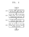
- FIG. 4 is a flowchart to explain the operations of an image signal processor according to an exemplary embodiment of the present invention.
- the reverse gamma compensation unit 105 in operation S200 performs reverse gamma compensation of an RGB image signal received by the image signal processing unit 106 and outputs the result.
- the pattern generating unit 107 divides one frame of the received image signal into a first group subfields and a second group subfields.
- the pattern generating unit 107 uses the pseudo 100 Hz driving scheme to divide the subfields of one frame of the RGB image signal into the first group subfields and the second group subfields that have the symmetric pattern to each other, and outputs the result.
- the motion estimation unit 103 estimates the motion vectors of the received image signal.
- the motion estimation unit 103 estimates the motion vector between the current frame and the previous frame output from the frame delay unit 101, and outputs the result.
- the pattern moving unit 109 moves the pattern of one of the first group subfields and the second group subfields based on the motion vector.
- the pattern moving unit 109 moves the pattern of the first group subfields SF1, SF2, ..., SF7 opposite to the movement direction of human eye, or alternatively, moves the pattern of the second group subfields SF8, SF9, ..., SF14 coincidental to the movement direction of the human eye.
- the pattern moving unit 109 may move the pattern of the first group subfields SF1, SF2, ..., SF7 or the pattern of the second group subfields SF8, SF9, ..., SF14 by a half of the motion vector size, or by the motion vector size multiplied by the physical time at which the second group begins.
- the pattern moving unit 109 moves the pattern of the first group subfields SF1, SF2, ..., SF7 or the second group subfields SF8, SF9, ..., SF14 based on the motion vector size.
- the image signal processor 98 described above includes the image signal processing unit 100 and the panel driving unit 150, this should not be construed as limiting.
- the image signal processor 98 according to an exemplary embodiment of the present invention may be implemented as a broadcast receiving apparatus which receives and processes an image signal included in a broadcast transmitted from a broadcast station.
- the concept of the present invention is not limited to the example of image enhancement of the PAL image signal described above.
- the PAL image signal may be displayed with high resolution.
Landscapes
- Engineering & Computer Science (AREA)
- Physics & Mathematics (AREA)
- Computer Hardware Design (AREA)
- General Physics & Mathematics (AREA)
- Theoretical Computer Science (AREA)
- Multimedia (AREA)
- Signal Processing (AREA)
- Power Engineering (AREA)
- Plasma & Fusion (AREA)
- Control Of Indicators Other Than Cathode Ray Tubes (AREA)
- Control Of Gas Discharge Display Tubes (AREA)
Applications Claiming Priority (1)
| Application Number | Priority Date | Filing Date | Title |
|---|---|---|---|
| KR1020070102504A KR20090037084A (ko) | 2007-10-11 | 2007-10-11 | 영상신호처리장치 및 그의 영상신호처리방법 |
Publications (1)
| Publication Number | Publication Date |
|---|---|
| EP2048873A1 true EP2048873A1 (de) | 2009-04-15 |
Family
ID=40254486
Family Applications (1)
| Application Number | Title | Priority Date | Filing Date |
|---|---|---|---|
| EP08162072A Ceased EP2048873A1 (de) | 2007-10-11 | 2008-08-08 | Bildsignalprozessor und Verfahren dafür |
Country Status (3)
| Country | Link |
|---|---|
| US (1) | US20090096932A1 (de) |
| EP (1) | EP2048873A1 (de) |
| KR (1) | KR20090037084A (de) |
Families Citing this family (2)
| Publication number | Priority date | Publication date | Assignee | Title |
|---|---|---|---|---|
| US8659701B2 (en) * | 2011-12-19 | 2014-02-25 | Sony Corporation | Usage of dither on interpolated frames |
| US12106451B2 (en) * | 2021-01-22 | 2024-10-01 | Cvitek Co. Ltd. | Block-based noise reduction intensity determination method and device |
Citations (5)
| Publication number | Priority date | Publication date | Assignee | Title |
|---|---|---|---|---|
| US20010012075A1 (en) | 1998-08-07 | 2001-08-09 | Carlos Correa | Method and apparatus for processing video pictures, especially for false contour effect compensation |
| EP1303136A2 (de) | 2001-10-09 | 2003-04-16 | Sony Corporation | Verfahren und Vorrichtung zum Verarbeiten eines Bildsignals |
| EP1351494A2 (de) * | 2002-04-03 | 2003-10-08 | Sony Corporation | Bewegungsvektordetektor und Vorrichtung zur Bewegungsvektordetektion |
| US20040046716A1 (en) * | 2001-01-31 | 2004-03-11 | Bertrand Chupeau | Method for displaying video images on a plasma display panel and corresponding plasma display panel |
| US20040179030A1 (en) * | 2003-03-11 | 2004-09-16 | Cole James R. | Image display system and method including optical scaling |
Family Cites Families (7)
| Publication number | Priority date | Publication date | Assignee | Title |
|---|---|---|---|---|
| JPH1115429A (ja) * | 1997-06-20 | 1999-01-22 | Fujitsu General Ltd | 動きベクトル時間軸処理方式 |
| KR100905936B1 (ko) * | 2001-02-21 | 2009-07-06 | 코닌클리케 필립스 일렉트로닉스 엔.브이. | 픽셀들을 디스플레이하기 위한 이미지 디스플레이 유닛 및 방법과 이와 같은 디스플레이 유닛을 포함하는 이미지 디스플레이 장치 |
| CN1554081A (zh) * | 2001-07-09 | 2004-12-08 | ���µ�����ҵ��ʽ���� | 等离子体显示面板的驱动方法以及等离子体显示面板的驱动装置 |
| JP3660610B2 (ja) * | 2001-07-10 | 2005-06-15 | 株式会社東芝 | 画像表示方法 |
| KR100472483B1 (ko) * | 2002-11-29 | 2005-03-10 | 삼성전자주식회사 | 의사 윤곽 제거 방법 및 이에 적합한 장치 |
| KR100497234B1 (ko) * | 2003-10-01 | 2005-06-23 | 삼성에스디아이 주식회사 | 플라즈마 디스플레이 패널의 화상 표시 방법 및 그 장치 |
| JP2008261984A (ja) * | 2007-04-11 | 2008-10-30 | Hitachi Ltd | 画像処理方法及びこれを用いた画像表示装置 |
-
2007
- 2007-10-11 KR KR1020070102504A patent/KR20090037084A/ko not_active Withdrawn
-
2008
- 2008-08-08 EP EP08162072A patent/EP2048873A1/de not_active Ceased
- 2008-09-15 US US12/210,622 patent/US20090096932A1/en not_active Abandoned
Patent Citations (5)
| Publication number | Priority date | Publication date | Assignee | Title |
|---|---|---|---|---|
| US20010012075A1 (en) | 1998-08-07 | 2001-08-09 | Carlos Correa | Method and apparatus for processing video pictures, especially for false contour effect compensation |
| US20040046716A1 (en) * | 2001-01-31 | 2004-03-11 | Bertrand Chupeau | Method for displaying video images on a plasma display panel and corresponding plasma display panel |
| EP1303136A2 (de) | 2001-10-09 | 2003-04-16 | Sony Corporation | Verfahren und Vorrichtung zum Verarbeiten eines Bildsignals |
| EP1351494A2 (de) * | 2002-04-03 | 2003-10-08 | Sony Corporation | Bewegungsvektordetektor und Vorrichtung zur Bewegungsvektordetektion |
| US20040179030A1 (en) * | 2003-03-11 | 2004-09-16 | Cole James R. | Image display system and method including optical scaling |
Also Published As
| Publication number | Publication date |
|---|---|
| KR20090037084A (ko) | 2009-04-15 |
| US20090096932A1 (en) | 2009-04-16 |
Similar Documents
| Publication | Publication Date | Title |
|---|---|---|
| CN101647056B (zh) | 图像处理设备、图像显示器和图像处理方法 | |
| KR100309951B1 (ko) | 디스플레이구동방법및장치 | |
| EP1585090B1 (de) | Bildanzeigevorrichtung und bildanzeigeverfahren | |
| JP2005024690A (ja) | ディスプレイ装置およびディスプレイの駆動方法 | |
| US20100079669A1 (en) | Image display apparatus and image display method | |
| JPH10282930A (ja) | ディスプレイ装置の動画補正方法及び動画補正回路 | |
| WO2003091975A1 (en) | Image display device | |
| US7800691B2 (en) | Video signal processing apparatus, method of processing video signal, program for processing video signal, and recording medium having the program recorded therein | |
| CN100421461C (zh) | 显示设备及其控制方法 | |
| KR20090038437A (ko) | 화상 처리 장치 및 화상 처리 방법 | |
| EP2048873A1 (de) | Bildsignalprozessor und Verfahren dafür | |
| JP2005141203A (ja) | 画像表示方法および画像表示装置 | |
| KR20020014766A (ko) | 플라즈마 디스플레이 패널의 표시계조 처리방법 | |
| KR100687558B1 (ko) | 화상 표시 방법 및 화상 표시 장치 | |
| JP2001034223A (ja) | 動画像表示方法及びそれを用いた動画像表示装置 | |
| US20070222712A1 (en) | Image Display Apparatus and Method of Driving the Same | |
| EP2048644A2 (de) | Bildsignalprozessor und entsprechendes Verfahren | |
| KR100825355B1 (ko) | 화상 표시 장치 및 그 구동 방법 | |
| JP2008256986A (ja) | 画像処理方法及びこれを用いた画像表示装置 | |
| KR100421482B1 (ko) | 플라즈마 디스플레이 패널의 영상신호 처리 방법 및 장치 | |
| JPH117266A (ja) | ディスプレイパネルの映像表示方式およびその装置 | |
| KR100447133B1 (ko) | 플라즈마 디스플레이 패널의 영상신호 처리 방법 및 장치 | |
| EP1696407A1 (de) | Bildanzeigeverfahren und bildanzeige | |
| KR100425486B1 (ko) | 플라즈마 디스플레이 패널의 영상신호 처리 장치 | |
| JP2004004782A (ja) | 画像表示装置 |
Legal Events
| Date | Code | Title | Description |
|---|---|---|---|
| PUAI | Public reference made under article 153(3) epc to a published international application that has entered the european phase |
Free format text: ORIGINAL CODE: 0009012 |
|
| AK | Designated contracting states |
Kind code of ref document: A1 Designated state(s): AT BE BG CH CY CZ DE DK EE ES FI FR GB GR HR HU IE IS IT LI LT LU LV MC MT NL NO PL PT RO SE SI SK TR |
|
| AX | Request for extension of the european patent |
Extension state: AL BA MK RS |
|
| 17P | Request for examination filed |
Effective date: 20090915 |
|
| 17Q | First examination report despatched |
Effective date: 20091007 |
|
| AKX | Designation fees paid |
Designated state(s): DE GB NL |
|
| STAA | Information on the status of an ep patent application or granted ep patent |
Free format text: STATUS: THE APPLICATION HAS BEEN REFUSED |
|
| 18R | Application refused |
Effective date: 20100902 |