EP2049827B1 - Purgeur de vapeur d'eau - Google Patents
Purgeur de vapeur d'eau Download PDFInfo
- Publication number
- EP2049827B1 EP2049827B1 EP20070874999 EP07874999A EP2049827B1 EP 2049827 B1 EP2049827 B1 EP 2049827B1 EP 20070874999 EP20070874999 EP 20070874999 EP 07874999 A EP07874999 A EP 07874999A EP 2049827 B1 EP2049827 B1 EP 2049827B1
- Authority
- EP
- European Patent Office
- Prior art keywords
- orifice
- steam trap
- condensate
- steam
- orifices
- Prior art date
- Legal status (The legal status is an assumption and is not a legal conclusion. Google has not performed a legal analysis and makes no representation as to the accuracy of the status listed.)
- Active
Links
Images






Classifications
-
- F—MECHANICAL ENGINEERING; LIGHTING; HEATING; WEAPONS; BLASTING
- F16—ENGINEERING ELEMENTS AND UNITS; GENERAL MEASURES FOR PRODUCING AND MAINTAINING EFFECTIVE FUNCTIONING OF MACHINES OR INSTALLATIONS; THERMAL INSULATION IN GENERAL
- F16T—STEAM TRAPS OR LIKE APPARATUS FOR DRAINING-OFF LIQUIDS FROM ENCLOSURES PREDOMINANTLY CONTAINING GASES OR VAPOURS
- F16T1/00—Steam traps or like apparatus for draining-off liquids from enclosures predominantly containing gases or vapours, e.g. gas lines, steam lines, containers
- F16T1/20—Steam traps or like apparatus for draining-off liquids from enclosures predominantly containing gases or vapours, e.g. gas lines, steam lines, containers with valves controlled by floats
- F16T1/22—Steam traps or like apparatus for draining-off liquids from enclosures predominantly containing gases or vapours, e.g. gas lines, steam lines, containers with valves controlled by floats of closed-hollow-body type
- F16T1/24—Steam traps or like apparatus for draining-off liquids from enclosures predominantly containing gases or vapours, e.g. gas lines, steam lines, containers with valves controlled by floats of closed-hollow-body type using levers
-
- Y—GENERAL TAGGING OF NEW TECHNOLOGICAL DEVELOPMENTS; GENERAL TAGGING OF CROSS-SECTIONAL TECHNOLOGIES SPANNING OVER SEVERAL SECTIONS OF THE IPC; TECHNICAL SUBJECTS COVERED BY FORMER USPC CROSS-REFERENCE ART COLLECTIONS [XRACs] AND DIGESTS
- Y10—TECHNICAL SUBJECTS COVERED BY FORMER USPC
- Y10T—TECHNICAL SUBJECTS COVERED BY FORMER US CLASSIFICATION
- Y10T137/00—Fluid handling
- Y10T137/2931—Diverse fluid containing pressure systems
- Y10T137/3003—Fluid separating traps or vents
- Y10T137/3021—Discriminating outlet for liquid
- Y10T137/304—With fluid responsive valve
- Y10T137/3043—Successively opened valves
-
- Y—GENERAL TAGGING OF NEW TECHNOLOGICAL DEVELOPMENTS; GENERAL TAGGING OF CROSS-SECTIONAL TECHNOLOGIES SPANNING OVER SEVERAL SECTIONS OF THE IPC; TECHNICAL SUBJECTS COVERED BY FORMER USPC CROSS-REFERENCE ART COLLECTIONS [XRACs] AND DIGESTS
- Y10—TECHNICAL SUBJECTS COVERED BY FORMER USPC
- Y10T—TECHNICAL SUBJECTS COVERED BY FORMER US CLASSIFICATION
- Y10T137/00—Fluid handling
- Y10T137/2931—Diverse fluid containing pressure systems
- Y10T137/3003—Fluid separating traps or vents
- Y10T137/3021—Discriminating outlet for liquid
- Y10T137/304—With fluid responsive valve
- Y10T137/3046—Gas collecting float [e.g., inverted bucket]
-
- Y—GENERAL TAGGING OF NEW TECHNOLOGICAL DEVELOPMENTS; GENERAL TAGGING OF CROSS-SECTIONAL TECHNOLOGIES SPANNING OVER SEVERAL SECTIONS OF THE IPC; TECHNICAL SUBJECTS COVERED BY FORMER USPC CROSS-REFERENCE ART COLLECTIONS [XRACs] AND DIGESTS
- Y10—TECHNICAL SUBJECTS COVERED BY FORMER USPC
- Y10T—TECHNICAL SUBJECTS COVERED BY FORMER US CLASSIFICATION
- Y10T137/00—Fluid handling
- Y10T137/2931—Diverse fluid containing pressure systems
- Y10T137/3003—Fluid separating traps or vents
- Y10T137/3021—Discriminating outlet for liquid
- Y10T137/304—With fluid responsive valve
- Y10T137/3052—Level responsive
- Y10T137/3068—Float
Definitions
- This invention relates to a steam trap and more particularly to a float type steam trap.
- Steam traps are automatic valves that release condensed steam [condensate] from a steam space while preventing the loss of live steam. They also remove air and non-condensable particles from the steam space.
- Steam traps are generally installed at the transition point of high pressure steam systems and low pressure condensate (water) collection systems. Steam traps are designed to prevent loss of heat energy from the system and at the same time quickly remove condensate from the high pressure steam system space.
- Mechanical Type steam traps operate on sensing difference in the fluid densities.
- a ball type float or an inverted bucket is used to sense the presence of condensed water in the trap and open the orifice to discharge the condensate and close as soon as water level drops to a pre set level.
- Thermodynamic steam traps operate on sensing the change in fluid dynamics of steam. This type of trap operates on the difference in velocity or kinetic energy between steam and condensate passing through a fixed or modulating orifice.
- Steam traps may also be classified on the basis of their generic operations i.e. “continuous flow” and “intermittent flow.”
- Thermostatic traps are fully open at start-up and vent the air trapped in the steam system easily. Float traps are normally provided with an inbuilt thermostatic air vent to fulfill this function. Thermodynamic traps are quite capable of handling moderate amounts of air. However, the small hole in fixed orifice condensate outlet and the bleed hole in inverted bucket traps both vent air slowly. Improper air venting will increase production times, warm-up times, and corrosion.
- This invention relates to the mechanical type steam trap and particularly to a float type mechanical steam trap.
- a float valve typically consists of an air tight enclosed ball made of metal or synthetic polymer material connected at the end of a pivoted arm positioned in side a chamber.
- a fluid enters the chamber, the ball floats in a fluid such as water and the ball along with its arm tend to move up and down.
- This up and down movement is used to advantage by connecting an orifice opening and closing element at the end of the arm distal to the ball.
- This mechanism therefore acts as a valve for controlling the flow of fluid such as water through the orifice.
- Float type steam traps are so called because they have this type of mechanism installed therein.
- US Patent 4387733 reveals a dual fulcrum steam trap having a large initial mechanical advantage and hemispherical valve seat with large contact area, to obtain extended operating life.
- the orifice size is fixed the condensate discharge rate will be limited to the size of the trap selected and will not be able to handle variable condensate loads effectively.
- US Patent 4545397 reveals a float valve without a lever mechanism, wherein the outer surface of a hollow spherical float operates to open and close an orifice located in the valve seat.
- the orifice size is related and limited to the size of the float and the trap selected and will not be able to handle variable condensate loads effectively.
- US Patent 4623091 reveals a float and thermostatic steam trap, in which venting and trapping functions are done by the same valve as the thermostatic actuator acts on the float linkage when the temperature is below a predetermined value. In start-up conditions and when temperature is below the predetermined value the thermostatic actuator engages, forcing the float assembly of the valve to remain open, to vent air and condensate quickly. At temperatures above the preset value the thermostatic actuator disengages completely to allow the float to open and close depending on the level of condensate in the trap chamber. Steam trap as disclosed in this document is able to handle air venting and start-up condensate loads effectively but fails to address the problem of varying condensate loads in conditions above the preset temperature. A steam trap of this design will have to be sized to meet the maximum possible condensate load for any specific application and therefore is likely to be bulky and more expensive.
- US Patent 7096880 reveals a float operated steam trap, in this invention a valve closing member slides over a fixed seat to open and close two or more orifices.
- the float lever carrying the valve closing member uses the force developed by the float to slide the seat across the face of the fixed orifice.
- the closing member has a surface contact with the valve seat and no positive pressure is applied on the valve closing member to seal it against the valve seat. This will lead to leakage through the orifice, wear and tear due to sliding friction, and the float will have to move over a larger arc with reference to point of pivot specially if the pivot arm is short, to fully open the orifice. As the orifice is not fully open able, condensate flow will be proportionately reduced and larger sized trap will have to be used to handle the required flow rate.
- US Patent 7171 976 reveals a float operated steam trap with collinear inlet and outlet with threaded connection that is easy to install and prevents leakage of live steam. In this invention no provision is made to take care of start-up air venting and fluctuating condensate loads that are encountered in normal operations.
- US2737364 discloses a steam trap including a link pivoted, as at, at its upper end to a float arm and depends therefrom with its lower end pivoted, to the rear end of a valve opening and closing rocker arm below a valve seat formed by an inverted T-shaped fitting threaded upwardly into the bottom of the casting.
- This invention seeks to overcome the limitation of the existing prior arts.
- Another object of this invention is to provide a float type steam trap that is optimum in size.
- Another object of this invention is to provide a float type steam trap wherein the size of installation is reduced.
- Yet another object of this invention is to provide a float type steam trap with a wide range of operating condensate load and pressure difference across the trap to overcome the difficulty of selection and sizing.
- said chamber is defined by a base and a cover bolted together to form the enclosed space to make the chamber openable and said inlet, and outlet are defined in said cover.
- said orifices are provided with resilient lips for resilient abutment of the elements with the orifices.
- two second orifices are provided on either side of a first orifice and two second elements are provided and said lever and link arrangement actuates the first and the two second elements.
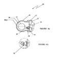
- FIG 4a shows details of a portion of the trap of figure 4a , with both the orifices in closed position.
- Figure 5a shows the position when condensate enters the trap chamber 28, and the condensate level 28(b) raises and the buoyancy of the float duly amplified by the first lever 18 lifts the orifice closing element 30, from the first orifice seat allowing condensate to pass through the orifice to the outlet. However the second orifice remains closed as the first lever 18 has not yet engaged the second lever 20.
- Figure 5b shows details of a portion of the trap of figure 5a , with the first orifice being open and the second orifice being closed.
- Figure 6a shows the position when more condensate enters the trap chamber 28.
- the condensate level 28(c) rises the float to its topmost position and the first lever 18 engages the second lever 20 to lift both the orifice closing elements 30 and 32 off the orifice seats. In this position both the orifices discharge condensate through the outlet.
- Figure 6b shows details of a portion of the trap of figure 6a with both the orifices in the open position.
- the cross member 36 is replaced by a resilient spring member 44 to damp the closing and opening movement of the second orifice.
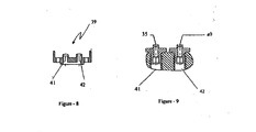
- Figure 8 shows a typical design of orifices made as a single component 39. Orifice seats are subject to erosion and wear and tear in constant use and are replaced in scheduled periodic maintenance operations. Orifices made as a single component are easier to assemble and requires less bolting/fastening members.
- Figure 9 shows an alternative design of an orifice made as a separate component 35 or 40. This design enables replacement of separate orifice seats depending on the condition as and when required. The orifice seats are easier to manufacture and store.
- Figure 10 shows a sectional plan view of an alternative embodiment of the invention with multi-orifices (not particularly numbered) comprising first orifice closing element 30, second orifice closing element 32 and a third orifice closing element 46 are seen in the figure 10 .
- a single float 16 operates the lever system for opening and closing the orifices.
- Figure 12 shows an alternative embodiment of the invention with multi-orifice and sliding element mechanism 53, operated by float 16 and lever arrangement 18 for opening and closing the exit orifices 54 and 56.
- Figure 13 is a graphical representation of the results of the experiments, plotted with differential pressure in x-axis and discharge rate in y-axis.
- Graph marked 58 depicts the test results for a conventional single orifice float type steam trap and graph marked 60 is for steam trap as envisaged in this invention.
- the condensate discharge rate is constant at approximately at 480 Kgs/hr up to a differential pressure of 2 bar (gauge) and rises to about 590 Kgs/hr at 4 bar (gauge).
- the second orifice increases the discharge rate to 620 Kgs/hr at 1 bar (g) differential pressure and up to 1000 Kgs/hr at 4 bar (gauge).
- the discharge rate improves considerably at reduced flow velocities thereby reducing erosion and wear and tear of the orifices.
- Figure 14 shows a capacity improvement factor chart based on the discharge ratio of the above test result wherein discharge ratio is plotted in y-axis and differential pressures in x axis.
- the graph shows clearly improvement achieved in discharge capacity of the steam trap of this invention.
Landscapes
- Engineering & Computer Science (AREA)
- General Engineering & Computer Science (AREA)
- Mechanical Engineering (AREA)
- Float Valves (AREA)
Claims (15)
- Un purgeur de vapeur d'eau comprenant:i. une chambre (28) définissant un espace clos, des moyens d'admission (15) pour introduire la vapeur d'eau contenant le condensat dans ledit espace, et des moyens de sortie (17) pour le condensat;ii. un premier orifice (35) conduisant auxdits moyens de sortie (17) pour le condensat;iii. au moins un deuxième orifice (40) conduisant auxdits moyens de sortie (17) pour le condensat;iv. un premier élément (30) pour commander l'ouverture dudit premier orifice ;v. au moins un deuxième élément (32) pour commander l'ouverture dudit au moins un deuxième orifice;vi. un dispositif de leviers et de liaisons (18, 20) coopérant avec ledit premier élément (30) et ledit au moins un deuxième élément (32); etvii. un flotteur (16) monté sur le dispositif de leviers et de liaisons adapté pour être déplacé dans ledit espace clos, en réponse à un niveau de condensat présent dans ledit espace clos, depuis une première position dans laquelle tous les orifices sont fermés vers une deuxième position dans laquelle le dispositif de leviers et de liaisons actionne le premier élément pour découvrir le premier orifice et vers une troisième position ultérieure dans laquelle le premier et au moins un deuxième orifice est découvert pour l'expulsion du condensat de manière sélective à partir dudit premier orifice (35) uniquement ou des premier (35) et deuxième (40) orifices, caractérisé en ce que un élément souple (38) est fourni entre ledit dispositif de leviers et de liaisons (18, 20) et ledit deuxième élément (32) pour amortir l'ouverture et la fermeture dudit deuxième orifice (40).
- Un purgeur de vapeur d'eau (10) selon la revendication 1, dans laquelle ladite chambre (28) est définie par une base (12) et un couvercle (14) vissés ensemble pour former l'espace clos et permettre d'ouvrir la chambre (28) et lesdites entrées (15) et sorties (17) sont définies dans ledit couvercle (14).
- Un purgeur de vapeur d'eau (10) selon la revendication 1, dans laquelle lesdits éléments (30, 32) sont des billes dont les diamètres sont supérieurs à ceux des orifices.
- Un purgeur de vapeur d'eau (10) selon la revendication 1, dans laquelle le diamètre dudit premier orifice (35) est le même, plus petit ou plus grand que celui du deuxième orifice (40).
- Un purgeur de vapeur d'eau (10) selon la revendication 1, dans laquelle lesdits orifices (32, 40) sont fournis avec des joints à lèvres souples pour obtenir une butée souple des éléments avec les orifices.
- Un purgeur de vapeur d'eau (10) selon la revendication 1, dans laquelle ledit premier élément (30) et ledit au moins un deuxième élément (32) sont réglables par pivotement.
- Un purgeur de vapeur d'eau (10) selon la revendication 3, dans laquelle lesdites billes (30, 32) sont fixées par soudage respectivement aux ailes des membres réglables par pivotement dudit dispositif de leviers et de liaisons (18, 20).
- Un purgeur de vapeur d'eau (10) selon la revendication 7, dans laquelle lesdites ailes sont montées sur des pivots avec réglage angulaire sur un cadre pivotant.
- Un purgeur de vapeur d'eau (10) selon la revendication 1, dans laquelle une traverse (36) est montée entre ledit premier élément (30) et ledit au moins un deuxième élément (32) pour retarder le déclenchement du au moins un deuxième élément (32) par rapport au déclenchement du premier élément (30).
- Un purgeur de vapeur d'eau (10) selon la revendication 1, dans laquelle deux deuxièmes orifices (40) sont fournis de chaque côté d'un premier orifice (35) et deux deuxièmes éléments (32) sont fournis et ledit dispositif de leviers et de liaisons (18, 20) actionne le premier (30) et les deux deuxièmes éléments (32).
- Un purgeur de vapeur d'eau (10) selon la revendication 9, dans laquelle ladite traverse (36) elle-même est un élément souple.
- Un purgeur de vapeur d'eau selon la revendication 1, dans laquelle lesdits premier (30) et deuxième éléments (32) sont définis par un élément (52) rotatif placé entre le premier orifice (35) et l'au moins un deuxième orifice (40).
- Un purgeur de vapeur d'eau selon la revendication 1, dans laquelle ledit premier élément (30) et ledit au moins un deuxième élément (32) sont définis par un mécanisme (53) de roulement à éléments placé entre le premier orifice (35) et l'au moins un deuxième orifice (40).
- Un purgeur de vapeur d'eau (10) selon la revendication 1, dans laquelle lesdits orifices (35, 40) sont constitués d'un seul composant à siège remplaçable destiné à être monté à ladite chambre (28).
- Un purgeur de vapeur d'eau (10) selon la revendication 1, dans laquelle lesdits orifices (35, 40) sont constitués de sièges séparés dans des composants séparés et remplaçables.
Applications Claiming Priority (2)
| Application Number | Priority Date | Filing Date | Title |
|---|---|---|---|
| IN600MU2006 | 2006-04-17 | ||
| PCT/IN2007/000149 WO2009019711A2 (fr) | 2006-04-17 | 2007-04-17 | Purgeur de vapeur d'eau |
Publications (3)
| Publication Number | Publication Date |
|---|---|
| EP2049827A2 EP2049827A2 (fr) | 2009-04-22 |
| EP2049827A4 EP2049827A4 (fr) | 2013-06-26 |
| EP2049827B1 true EP2049827B1 (fr) | 2015-05-13 |
Family
ID=40341870
Family Applications (1)
| Application Number | Title | Priority Date | Filing Date |
|---|---|---|---|
| EP20070874999 Active EP2049827B1 (fr) | 2006-04-17 | 2007-04-17 | Purgeur de vapeur d'eau |
Country Status (5)
| Country | Link |
|---|---|
| US (1) | US8230872B2 (fr) |
| EP (1) | EP2049827B1 (fr) |
| JP (1) | JP5244799B2 (fr) |
| CN (1) | CN101720401B (fr) |
| WO (1) | WO2009019711A2 (fr) |
Cited By (2)
| Publication number | Priority date | Publication date | Assignee | Title |
|---|---|---|---|---|
| DE202017102807U1 (de) | 2017-05-10 | 2017-06-16 | Endress+Hauser Conducta Gmbh+Co. Kg | Dampfanalysesystem |
| WO2019215690A1 (fr) * | 2018-05-11 | 2019-11-14 | Forbes Marshall Pvt. Ltd. | Ensemble soupape pour purgeur de vapeur |
Families Citing this family (8)
| Publication number | Priority date | Publication date | Assignee | Title |
|---|---|---|---|---|
| WO2015186085A1 (fr) * | 2014-06-05 | 2015-12-10 | Forbes Marshall Private Ltd. | Purgeur de vapeur à raccord rotatif |
| KR200481165Y1 (ko) * | 2015-10-05 | 2016-08-29 | 티에스케이 주식회사 | 부구 보호수단이 적용되는 스팀트랩 |
| CN105864626A (zh) * | 2016-04-29 | 2016-08-17 | 潘豪杰 | 一种疏水阀 |
| EP3375504B1 (fr) * | 2017-03-14 | 2021-02-24 | Danfoss A/S | Soupape de vidange et agencement de soupape |
| PE20220907A1 (es) * | 2019-08-08 | 2022-05-30 | Tlv Co Ltd | Unidad de valvula de descarga y dispositivo de fluido |
| CN110566800B (zh) * | 2019-10-17 | 2024-09-03 | 荆门市中金铝业铸造有限公司 | 一种带有活塞排气装置的杠杆浮球式疏水阀 |
| KR102491317B1 (ko) * | 2022-04-18 | 2023-01-26 | 오순웅 | 멀티웨이 오리피스 스팀 트랩 |
| US20250137663A1 (en) * | 2023-10-31 | 2025-05-01 | Joseph Richter | Steam Trap Insulating Cover with Wireless Monitoring |
Family Cites Families (27)
| Publication number | Priority date | Publication date | Assignee | Title |
|---|---|---|---|---|
| DE86175C (fr) | ||||
| DE43838C (de) | B. PILZ in Chemnitz i. S,, Lindenstrafse 9 | Dampfwasser-Ableiter mit zwei Kolbenschiebern | ||
| US368101A (en) * | 1887-08-09 | Third to james thomas mcdougall | ||
| US668302A (en) * | 1900-12-17 | 1901-02-19 | Wright Mfg Company | Steam-trap. |
| US742308A (en) * | 1903-04-21 | 1903-10-27 | Nat Dry Kiln Company | Steam-trap. |
| DE425741C (de) | 1924-08-08 | 1926-02-24 | Gustav Mankenberg Fa | Dampfwasserableiter mit zwei verschieden grossen Auslassventilen |
| US2737364A (en) | 1953-04-06 | 1956-03-06 | David P Handwerk | Condensation trap |
| US2790456A (en) * | 1953-09-14 | 1957-04-30 | Perfecting Sevice Co | Steam trap |
| GB774561A (en) * | 1955-01-10 | 1957-05-08 | Perfecting Service Company | Valve mechanism for a condensate trap |
| FR1123351A (fr) | 1955-03-09 | 1956-09-20 | Perfectionnements aux purgeurs automatiques | |
| US3011719A (en) * | 1959-05-06 | 1961-12-05 | Jorgensen Emanuel | Float actuated valves |
| US4276354A (en) * | 1979-11-19 | 1981-06-30 | The Clark-Reliance Corporation | Steam traps or the like |
| US4387733A (en) * | 1981-05-19 | 1983-06-14 | The Clark Reliance Corp. | Dual fulcrum steam trap |
| JPS5969596A (ja) * | 1982-10-08 | 1984-04-19 | 株式会社 テイエルブイ | フロ−ト弁の構造 |
| US4623091A (en) * | 1984-03-22 | 1986-11-18 | Marcel Stein | Integrated float and thermostatic steam trap |
| DE3543674C1 (de) * | 1985-12-11 | 1987-06-19 | Gestra Ag | Kondensatableiter |
| CN87209984U (zh) * | 1987-07-15 | 1988-04-13 | 首都钢铁公司 | 压缩气体疏液排污阀 |
| JPH0716160Y2 (ja) * | 1988-07-05 | 1995-04-12 | 株式会社ミヤワキ | フロート式ドレントラツプ |
| JPH06100317B2 (ja) * | 1989-02-15 | 1994-12-12 | 株式会社テイエルブイ | フロート弁 |
| CN1047376A (zh) * | 1989-05-15 | 1990-11-28 | 沈阳市节能技术服务中心 | 旋转轴浮球式疏水阀 |
| GB2320549A (en) * | 1996-12-18 | 1998-06-24 | Spirax Sarco Ltd | Float operated valve assembly |
| GB2320550A (en) * | 1996-12-18 | 1998-06-24 | Spirax Sarco Ltd | Valve assembly |
| JP3983349B2 (ja) * | 1997-09-12 | 2007-09-26 | 株式会社テイエルブイ | 殺菌部材を有する液体排出弁 |
| JP2000266287A (ja) * | 1999-01-14 | 2000-09-26 | Tlv Co Ltd | フリーフロート式ドレントラップ |
| JP2001141189A (ja) * | 1999-11-16 | 2001-05-25 | Tlv Co Ltd | フロート式ドレントラップ |
| US7096880B2 (en) | 2003-07-09 | 2006-08-29 | Kabushiki Kaisha Motoyamaseisakusho | Float type steam trap |
| KR200372296Y1 (ko) | 2004-09-18 | 2005-01-10 | 주순규 | 해머가 형성된 스팀트랩 |
-
2007
- 2007-04-17 EP EP20070874999 patent/EP2049827B1/fr active Active
- 2007-04-17 JP JP2009526261A patent/JP5244799B2/ja active Active
- 2007-04-17 WO PCT/IN2007/000149 patent/WO2009019711A2/fr not_active Ceased
- 2007-04-17 CN CN200780022498.XA patent/CN101720401B/zh active Active
- 2007-04-17 US US12/297,479 patent/US8230872B2/en active Active
Cited By (2)
| Publication number | Priority date | Publication date | Assignee | Title |
|---|---|---|---|---|
| DE202017102807U1 (de) | 2017-05-10 | 2017-06-16 | Endress+Hauser Conducta Gmbh+Co. Kg | Dampfanalysesystem |
| WO2019215690A1 (fr) * | 2018-05-11 | 2019-11-14 | Forbes Marshall Pvt. Ltd. | Ensemble soupape pour purgeur de vapeur |
Also Published As
| Publication number | Publication date |
|---|---|
| CN101720401A (zh) | 2010-06-02 |
| WO2009019711A2 (fr) | 2009-02-12 |
| CN101720401B (zh) | 2014-01-15 |
| EP2049827A4 (fr) | 2013-06-26 |
| US20100170575A1 (en) | 2010-07-08 |
| JP2010506100A (ja) | 2010-02-25 |
| US8230872B2 (en) | 2012-07-31 |
| EP2049827A2 (fr) | 2009-04-22 |
| WO2009019711A3 (fr) | 2010-01-14 |
| JP5244799B2 (ja) | 2013-07-24 |
Similar Documents
| Publication | Publication Date | Title |
|---|---|---|
| EP2049827B1 (fr) | Purgeur de vapeur d'eau | |
| US5401142A (en) | Condensate discharging device | |
| US4623091A (en) | Integrated float and thermostatic steam trap | |
| KR100629440B1 (ko) | 온도센서를 이용한 스팀트랩 | |
| US20070215208A1 (en) | Float type steam trap | |
| US4706699A (en) | Steam trap | |
| US20060207669A1 (en) | Valve structure and control techniques | |
| US2825508A (en) | Mono valve float thermostatic steam trap | |
| JP2003240190A (ja) | フロート式スチームトラップ | |
| JPH0953795A (ja) | バルブ付スチ―ムトラップ | |
| JP3455330B2 (ja) | 大容量スチ―ムトラップ | |
| JPH0637275Y2 (ja) | パイロット式スチームトラップ | |
| JP2884297B2 (ja) | パイロット式スチ―ムトラップ | |
| JP4334690B2 (ja) | フロート式ドレントラップ | |
| US2929559A (en) | Condensate discharging device | |
| JPH0637272Y2 (ja) | パイロット式スチームトラップ | |
| JP2961346B2 (ja) | パイロット式スチ―ムトラップ | |
| Armer | The right steam trap? | |
| JPH0716959Y2 (ja) | パイロット式スチームトラップ | |
| JP3443613B2 (ja) | 大容量スチ―ムトラップ | |
| JP5455544B2 (ja) | パイロット式スチームトラップ | |
| JP2961345B2 (ja) | パイロット式スチ―ムトラップ | |
| JPH10176791A (ja) | スチ―ムトラップ | |
| JP2961343B2 (ja) | パイロット式スチ―ムトラップ | |
| JPH1089595A (ja) | パイロット式スチ―ムトラップ |
Legal Events
| Date | Code | Title | Description |
|---|---|---|---|
| PUAI | Public reference made under article 153(3) epc to a published international application that has entered the european phase |
Free format text: ORIGINAL CODE: 0009012 |
|
| 17P | Request for examination filed |
Effective date: 20081117 |
|
| AK | Designated contracting states |
Kind code of ref document: A2 Designated state(s): AT BE BG CH CY CZ DE DK EE ES FI FR GB GR HU IE IS IT LI LT LU LV MC MT NL PL PT RO SE SI SK TR |
|
| AX | Request for extension of the european patent |
Extension state: AL BA HR MK RS |
|
| DAX | Request for extension of the european patent (deleted) | ||
| R17D | Deferred search report published (corrected) |
Effective date: 20100114 |
|
| RIC1 | Information provided on ipc code assigned before grant |
Ipc: F16T 1/24 20060101ALI20100316BHEP Ipc: F16T 1/40 20060101ALI20100316BHEP Ipc: F16T 1/22 20060101ALI20100316BHEP Ipc: F16T 1/20 20060101AFI20100316BHEP |
|
| RBV | Designated contracting states (corrected) |
Designated state(s): AT BE BG CH CY CZ DE DK EE ES FI FR GB GR HU IE IS IT LI LT LU LV MC MT NL PL PT RO SE SI SK TR |
|
| A4 | Supplementary search report drawn up and despatched |
Effective date: 20130524 |
|
| RIC1 | Information provided on ipc code assigned before grant |
Ipc: F16T 1/24 20060101ALI20130517BHEP Ipc: F16T 1/22 20060101ALI20130517BHEP Ipc: F16T 1/40 20060101ALI20130517BHEP Ipc: F16T 1/20 20060101AFI20130517BHEP |
|
| 17Q | First examination report despatched |
Effective date: 20140303 |
|
| GRAP | Despatch of communication of intention to grant a patent |
Free format text: ORIGINAL CODE: EPIDOSNIGR1 |
|
| INTG | Intention to grant announced |
Effective date: 20141014 |
|
| GRAJ | Information related to disapproval of communication of intention to grant by the applicant or resumption of examination proceedings by the epo deleted |
Free format text: ORIGINAL CODE: EPIDOSDIGR1 |
|
| GRAP | Despatch of communication of intention to grant a patent |
Free format text: ORIGINAL CODE: EPIDOSNIGR1 |
|
| GRAJ | Information related to disapproval of communication of intention to grant by the applicant or resumption of examination proceedings by the epo deleted |
Free format text: ORIGINAL CODE: EPIDOSDIGR1 |
|
| GRAP | Despatch of communication of intention to grant a patent |
Free format text: ORIGINAL CODE: EPIDOSNIGR1 |
|
| GRAP | Despatch of communication of intention to grant a patent |
Free format text: ORIGINAL CODE: EPIDOSNIGR1 |
|
| GRAS | Grant fee paid |
Free format text: ORIGINAL CODE: EPIDOSNIGR3 |
|
| INTG | Intention to grant announced |
Effective date: 20150316 |
|
| GRAA | (expected) grant |
Free format text: ORIGINAL CODE: 0009210 |
|
| RAP1 | Party data changed (applicant data changed or rights of an application transferred) |
Owner name: FORBES MARSHALL STEAM SYSTEMS PRIVATE LIMITED |
|
| AK | Designated contracting states |
Kind code of ref document: B1 Designated state(s): AT BE BG CH CY CZ DE DK EE ES FI FR GB GR HU IE IS IT LI LT LU LV MC MT NL PL PT RO SE SI SK TR |
|
| REG | Reference to a national code |
Ref country code: GB Ref legal event code: FG4D |
|
| REG | Reference to a national code |
Ref country code: CH Ref legal event code: EP |
|
| REG | Reference to a national code |
Ref country code: IE Ref legal event code: FG4D |
|
| REG | Reference to a national code |
Ref country code: AT Ref legal event code: REF Ref document number: 726986 Country of ref document: AT Kind code of ref document: T Effective date: 20150615 |
|
| REG | Reference to a national code |
Ref country code: DE Ref legal event code: R096 Ref document number: 602007041472 Country of ref document: DE Effective date: 20150625 |
|
| REG | Reference to a national code |
Ref country code: AT Ref legal event code: MK05 Ref document number: 726986 Country of ref document: AT Kind code of ref document: T Effective date: 20150513 |
|
| REG | Reference to a national code |
Ref country code: NL Ref legal event code: MP Effective date: 20150513 |
|
| REG | Reference to a national code |
Ref country code: LT Ref legal event code: MG4D |
|
| PG25 | Lapsed in a contracting state [announced via postgrant information from national office to epo] |
Ref country code: PT Free format text: LAPSE BECAUSE OF FAILURE TO SUBMIT A TRANSLATION OF THE DESCRIPTION OR TO PAY THE FEE WITHIN THE PRESCRIBED TIME-LIMIT Effective date: 20150914 Ref country code: LT Free format text: LAPSE BECAUSE OF FAILURE TO SUBMIT A TRANSLATION OF THE DESCRIPTION OR TO PAY THE FEE WITHIN THE PRESCRIBED TIME-LIMIT Effective date: 20150513 Ref country code: FI Free format text: LAPSE BECAUSE OF FAILURE TO SUBMIT A TRANSLATION OF THE DESCRIPTION OR TO PAY THE FEE WITHIN THE PRESCRIBED TIME-LIMIT Effective date: 20150513 Ref country code: ES Free format text: LAPSE BECAUSE OF FAILURE TO SUBMIT A TRANSLATION OF THE DESCRIPTION OR TO PAY THE FEE WITHIN THE PRESCRIBED TIME-LIMIT Effective date: 20150513 |
|
| PG25 | Lapsed in a contracting state [announced via postgrant information from national office to epo] |
Ref country code: GR Free format text: LAPSE BECAUSE OF FAILURE TO SUBMIT A TRANSLATION OF THE DESCRIPTION OR TO PAY THE FEE WITHIN THE PRESCRIBED TIME-LIMIT Effective date: 20150814 Ref country code: AT Free format text: LAPSE BECAUSE OF FAILURE TO SUBMIT A TRANSLATION OF THE DESCRIPTION OR TO PAY THE FEE WITHIN THE PRESCRIBED TIME-LIMIT Effective date: 20150513 Ref country code: IS Free format text: LAPSE BECAUSE OF FAILURE TO SUBMIT A TRANSLATION OF THE DESCRIPTION OR TO PAY THE FEE WITHIN THE PRESCRIBED TIME-LIMIT Effective date: 20150913 Ref country code: BG Free format text: LAPSE BECAUSE OF FAILURE TO SUBMIT A TRANSLATION OF THE DESCRIPTION OR TO PAY THE FEE WITHIN THE PRESCRIBED TIME-LIMIT Effective date: 20150813 Ref country code: LV Free format text: LAPSE BECAUSE OF FAILURE TO SUBMIT A TRANSLATION OF THE DESCRIPTION OR TO PAY THE FEE WITHIN THE PRESCRIBED TIME-LIMIT Effective date: 20150513 |
|
| PG25 | Lapsed in a contracting state [announced via postgrant information from national office to epo] |
Ref country code: DK Free format text: LAPSE BECAUSE OF FAILURE TO SUBMIT A TRANSLATION OF THE DESCRIPTION OR TO PAY THE FEE WITHIN THE PRESCRIBED TIME-LIMIT Effective date: 20150513 Ref country code: EE Free format text: LAPSE BECAUSE OF FAILURE TO SUBMIT A TRANSLATION OF THE DESCRIPTION OR TO PAY THE FEE WITHIN THE PRESCRIBED TIME-LIMIT Effective date: 20150513 |
|
| REG | Reference to a national code |
Ref country code: DE Ref legal event code: R097 Ref document number: 602007041472 Country of ref document: DE |
|
| PG25 | Lapsed in a contracting state [announced via postgrant information from national office to epo] |
Ref country code: RO Free format text: LAPSE BECAUSE OF NON-PAYMENT OF DUE FEES Effective date: 20150513 Ref country code: CZ Free format text: LAPSE BECAUSE OF FAILURE TO SUBMIT A TRANSLATION OF THE DESCRIPTION OR TO PAY THE FEE WITHIN THE PRESCRIBED TIME-LIMIT Effective date: 20150513 Ref country code: PL Free format text: LAPSE BECAUSE OF FAILURE TO SUBMIT A TRANSLATION OF THE DESCRIPTION OR TO PAY THE FEE WITHIN THE PRESCRIBED TIME-LIMIT Effective date: 20150513 Ref country code: SK Free format text: LAPSE BECAUSE OF FAILURE TO SUBMIT A TRANSLATION OF THE DESCRIPTION OR TO PAY THE FEE WITHIN THE PRESCRIBED TIME-LIMIT Effective date: 20150513 |
|
| PLBE | No opposition filed within time limit |
Free format text: ORIGINAL CODE: 0009261 |
|
| STAA | Information on the status of an ep patent application or granted ep patent |
Free format text: STATUS: NO OPPOSITION FILED WITHIN TIME LIMIT |
|
| 26N | No opposition filed |
Effective date: 20160216 |
|
| REG | Reference to a national code |
Ref country code: FR Ref legal event code: PLFP Year of fee payment: 10 |
|
| PG25 | Lapsed in a contracting state [announced via postgrant information from national office to epo] |
Ref country code: IT Free format text: LAPSE BECAUSE OF FAILURE TO SUBMIT A TRANSLATION OF THE DESCRIPTION OR TO PAY THE FEE WITHIN THE PRESCRIBED TIME-LIMIT Effective date: 20150513 |
|
| PG25 | Lapsed in a contracting state [announced via postgrant information from national office to epo] |
Ref country code: SI Free format text: LAPSE BECAUSE OF FAILURE TO SUBMIT A TRANSLATION OF THE DESCRIPTION OR TO PAY THE FEE WITHIN THE PRESCRIBED TIME-LIMIT Effective date: 20150513 |
|
| REG | Reference to a national code |
Ref country code: CH Ref legal event code: PL |
|
| PG25 | Lapsed in a contracting state [announced via postgrant information from national office to epo] |
Ref country code: LU Free format text: LAPSE BECAUSE OF FAILURE TO SUBMIT A TRANSLATION OF THE DESCRIPTION OR TO PAY THE FEE WITHIN THE PRESCRIBED TIME-LIMIT Effective date: 20160417 |
|
| REG | Reference to a national code |
Ref country code: IE Ref legal event code: MM4A |
|
| PG25 | Lapsed in a contracting state [announced via postgrant information from national office to epo] |
Ref country code: LI Free format text: LAPSE BECAUSE OF NON-PAYMENT OF DUE FEES Effective date: 20160430 Ref country code: CH Free format text: LAPSE BECAUSE OF NON-PAYMENT OF DUE FEES Effective date: 20160430 |
|
| REG | Reference to a national code |
Ref country code: FR Ref legal event code: PLFP Year of fee payment: 11 |
|
| PG25 | Lapsed in a contracting state [announced via postgrant information from national office to epo] |
Ref country code: IE Free format text: LAPSE BECAUSE OF NON-PAYMENT OF DUE FEES Effective date: 20160417 |
|
| PG25 | Lapsed in a contracting state [announced via postgrant information from national office to epo] |
Ref country code: SE Free format text: LAPSE BECAUSE OF FAILURE TO SUBMIT A TRANSLATION OF THE DESCRIPTION OR TO PAY THE FEE WITHIN THE PRESCRIBED TIME-LIMIT Effective date: 20150513 Ref country code: NL Free format text: LAPSE BECAUSE OF FAILURE TO SUBMIT A TRANSLATION OF THE DESCRIPTION OR TO PAY THE FEE WITHIN THE PRESCRIBED TIME-LIMIT Effective date: 20150513 |
|
| REG | Reference to a national code |
Ref country code: FR Ref legal event code: PLFP Year of fee payment: 12 |
|
| PG25 | Lapsed in a contracting state [announced via postgrant information from national office to epo] |
Ref country code: HU Free format text: LAPSE BECAUSE OF FAILURE TO SUBMIT A TRANSLATION OF THE DESCRIPTION OR TO PAY THE FEE WITHIN THE PRESCRIBED TIME-LIMIT; INVALID AB INITIO Effective date: 20070417 Ref country code: CY Free format text: LAPSE BECAUSE OF FAILURE TO SUBMIT A TRANSLATION OF THE DESCRIPTION OR TO PAY THE FEE WITHIN THE PRESCRIBED TIME-LIMIT Effective date: 20150513 |
|
| PG25 | Lapsed in a contracting state [announced via postgrant information from national office to epo] |
Ref country code: MC Free format text: LAPSE BECAUSE OF FAILURE TO SUBMIT A TRANSLATION OF THE DESCRIPTION OR TO PAY THE FEE WITHIN THE PRESCRIBED TIME-LIMIT Effective date: 20150513 Ref country code: MT Free format text: LAPSE BECAUSE OF NON-PAYMENT OF DUE FEES Effective date: 20160430 |
|
| REG | Reference to a national code |
Ref country code: GB Ref legal event code: 732E Free format text: REGISTERED BETWEEN 20180927 AND 20181005 |
|
| REG | Reference to a national code |
Ref country code: BE Ref legal event code: FP Effective date: 20150810 Ref country code: BE Ref legal event code: PD Owner name: FORBES MARSHALL PVT LTD.; IN Free format text: DETAILS ASSIGNMENT: CHANGE OF OWNER(S), FUSION; FORMER OWNER NAME: FORBES MARSHALL STEAM SYSTEMS PRIVATE LIMITED Effective date: 20181008 |
|
| REG | Reference to a national code |
Ref country code: DE Ref legal event code: R081 Ref document number: 602007041472 Country of ref document: DE Owner name: FORBES MARSHALL PVT LTD., IN Free format text: FORMER OWNER: FORBES MARSHALL STEAM SYSTEMS PRIVATE LTD., PUNE, MAHARASHTRA, IN |
|
| P01 | Opt-out of the competence of the unified patent court (upc) registered |
Effective date: 20230620 |
|
| PGFP | Annual fee paid to national office [announced via postgrant information from national office to epo] |
Ref country code: DE Payment date: 20250313 Year of fee payment: 19 |
|
| PGFP | Annual fee paid to national office [announced via postgrant information from national office to epo] |
Ref country code: BE Payment date: 20250428 Year of fee payment: 19 |
|
| PGFP | Annual fee paid to national office [announced via postgrant information from national office to epo] |
Ref country code: FR Payment date: 20250424 Year of fee payment: 19 |
|
| PGFP | Annual fee paid to national office [announced via postgrant information from national office to epo] |
Ref country code: GB Payment date: 20260327 Year of fee payment: 20 |
|
| PGFP | Annual fee paid to national office [announced via postgrant information from national office to epo] |
Ref country code: TR Payment date: 20260325 Year of fee payment: 20 |