EP2050501A1 - Embout de distribution de liquide avec réservoir - Google Patents
Embout de distribution de liquide avec réservoir Download PDFInfo
- Publication number
- EP2050501A1 EP2050501A1 EP08253380A EP08253380A EP2050501A1 EP 2050501 A1 EP2050501 A1 EP 2050501A1 EP 08253380 A EP08253380 A EP 08253380A EP 08253380 A EP08253380 A EP 08253380A EP 2050501 A1 EP2050501 A1 EP 2050501A1
- Authority
- EP
- European Patent Office
- Prior art keywords
- container
- control solution
- dispensing tip
- reservoir
- dispensing
- Prior art date
- Legal status (The legal status is an assumption and is not a legal conclusion. Google has not performed a legal analysis and makes no representation as to the accuracy of the status listed.)
- Withdrawn
Links
- 239000007788 liquid Substances 0.000 title claims description 22
- 239000012530 fluid Substances 0.000 abstract description 35
- 239000006193 liquid solution Substances 0.000 abstract description 3
- 238000013508 migration Methods 0.000 abstract description 2
- 230000005012 migration Effects 0.000 abstract description 2
- 239000000243 solution Substances 0.000 description 77
- 238000012360 testing method Methods 0.000 description 35
- 230000009471 action Effects 0.000 description 9
- 239000012491 analyte Substances 0.000 description 7
- 238000000034 method Methods 0.000 description 7
- 239000003153 chemical reaction reagent Substances 0.000 description 5
- 239000003795 chemical substances by application Substances 0.000 description 5
- 238000004519 manufacturing process Methods 0.000 description 5
- 230000008901 benefit Effects 0.000 description 4
- 239000008280 blood Substances 0.000 description 4
- 210000004369 blood Anatomy 0.000 description 4
- 238000004891 communication Methods 0.000 description 4
- 238000005259 measurement Methods 0.000 description 4
- 238000013461 design Methods 0.000 description 3
- 239000000126 substance Substances 0.000 description 3
- WQZGKKKJIJFFOK-GASJEMHNSA-N Glucose Natural products OC[C@H]1OC(O)[C@H](O)[C@@H](O)[C@@H]1O WQZGKKKJIJFFOK-GASJEMHNSA-N 0.000 description 2
- HVYWMOMLDIMFJA-DPAQBDIFSA-N cholesterol Chemical compound C1C=C2C[C@@H](O)CC[C@]2(C)[C@@H]2[C@@H]1[C@@H]1CC[C@H]([C@H](C)CCCC(C)C)[C@@]1(C)CC2 HVYWMOMLDIMFJA-DPAQBDIFSA-N 0.000 description 2
- 239000000356 contaminant Substances 0.000 description 2
- 238000011109 contamination Methods 0.000 description 2
- 239000011521 glass Substances 0.000 description 2
- 239000008103 glucose Substances 0.000 description 2
- 230000000717 retained effect Effects 0.000 description 2
- 238000012956 testing procedure Methods 0.000 description 2
- 239000004480 active ingredient Substances 0.000 description 1
- 230000003466 anti-cipated effect Effects 0.000 description 1
- 239000012611 container material Substances 0.000 description 1
- 230000001419 dependent effect Effects 0.000 description 1
- 238000001514 detection method Methods 0.000 description 1
- 238000011161 development Methods 0.000 description 1
- 238000002405 diagnostic procedure Methods 0.000 description 1
- 239000003814 drug Substances 0.000 description 1
- 229940079593 drug Drugs 0.000 description 1
- 238000005516 engineering process Methods 0.000 description 1
- 238000011156 evaluation Methods 0.000 description 1
- 230000006872 improvement Effects 0.000 description 1
- 238000001746 injection moulding Methods 0.000 description 1
- 230000002045 lasting effect Effects 0.000 description 1
- 239000000463 material Substances 0.000 description 1
- 230000003278 mimic effect Effects 0.000 description 1
- 238000012544 monitoring process Methods 0.000 description 1
- 238000000465 moulding Methods 0.000 description 1
- 230000008569 process Effects 0.000 description 1
- 210000003296 saliva Anatomy 0.000 description 1
- 238000007789 sealing Methods 0.000 description 1
- 239000004094 surface-active agent Substances 0.000 description 1
- 210000002700 urine Anatomy 0.000 description 1
Images


Classifications
-
- B—PERFORMING OPERATIONS; TRANSPORTING
- B01—PHYSICAL OR CHEMICAL PROCESSES OR APPARATUS IN GENERAL
- B01L—CHEMICAL OR PHYSICAL LABORATORY APPARATUS FOR GENERAL USE
- B01L3/00—Containers or dishes for laboratory use, e.g. laboratory glassware; Droppers
- B01L3/02—Burettes; Pipettes
- B01L3/0241—Drop counters; Drop formers
- B01L3/0272—Dropper bottles
-
- B—PERFORMING OPERATIONS; TRANSPORTING
- B65—CONVEYING; PACKING; STORING; HANDLING THIN OR FILAMENTARY MATERIAL
- B65D—CONTAINERS FOR STORAGE OR TRANSPORT OF ARTICLES OR MATERIALS, e.g. BAGS, BARRELS, BOTTLES, BOXES, CANS, CARTONS, CRATES, DRUMS, JARS, TANKS, HOPPERS, FORWARDING CONTAINERS; ACCESSORIES, CLOSURES, OR FITTINGS THEREFOR; PACKAGING ELEMENTS; PACKAGES
- B65D47/00—Closures with filling and discharging, or with discharging, devices
- B65D47/04—Closures with discharging devices other than pumps
- B65D47/06—Closures with discharging devices other than pumps with pouring spouts or tubes; with discharge nozzles or passages
- B65D47/18—Closures with discharging devices other than pumps with pouring spouts or tubes; with discharge nozzles or passages for discharging drops; Droppers
-
- B—PERFORMING OPERATIONS; TRANSPORTING
- B01—PHYSICAL OR CHEMICAL PROCESSES OR APPARATUS IN GENERAL
- B01L—CHEMICAL OR PHYSICAL LABORATORY APPARATUS FOR GENERAL USE
- B01L2200/00—Solutions for specific problems relating to chemical or physical laboratory apparatus
- B01L2200/08—Ergonomic or safety aspects of handling devices
- B01L2200/087—Ergonomic aspects
-
- B—PERFORMING OPERATIONS; TRANSPORTING
- B01—PHYSICAL OR CHEMICAL PROCESSES OR APPARATUS IN GENERAL
- B01L—CHEMICAL OR PHYSICAL LABORATORY APPARATUS FOR GENERAL USE
- B01L2300/00—Additional constructional details
- B01L2300/04—Closures and closing means
- B01L2300/046—Function or devices integrated in the closure
- B01L2300/047—Additional chamber, reservoir
Definitions
- the invention relates to devices for containing and dispensing liquids.
- a liquid agent such as a medication or reagent.
- a liquid agent such as a medication or reagent.
- One such application in which precise amounts of reagent fluid are required is in the patient use of systems for measuring a bodily analyte in a physiological fluid.
- Such systems typically include test strips containing a reagent material to which a physiological sample is applied.
- Meters are configured to receive such test strips and determine the analyte concentration of the sample.
- a monitoring agent often called a control solution is used to test the accuracy and efficacy of the test strips.
- Control solutions are often packaged in a plastic or glass container with a dispensing end configured with a small opening at the end of a taper through which a relatively imprecise droplet of control solution can be dispensed by squeezing the bottle. It is generally difficult to accurately control the amount of control solution dispensed from such containers.
- improvements are rapidly being made in the development of systems and devices for measuring analyte concentrations, there has been limited advancement in the area of control solution containment and dispensing for use with these advanced systems and devices.
- Commercially available control solution containers typically have a tapered dispensing tip that performs reliably on diagnostic test strips where a large volume, e.g . 5 to 20 microliters, of control solution is required. However, such containers are less accurate at dispensing smaller volumes required by today's more advanced test strips that use less than one microliter.
- control solution may be delivered by the existing tapered dispensing tips, creating inconvenience and annoyance to the user. It can be difficult to aim a large droplet precisely onto the reaction zone of a test strip while also holding the bottle of control solution under pressure. This is particularly true for older patients or those with dexterity problems. Because the strip cannot absorb the excess control solution dispensed, the excess spills. This is particularly problematic because control solutions are typically red in color to realistically mimic blood.
- the present invention will be described in the context of analyte concentration measurement applications, and particularly in the context of glucose concentration in blood.
- the subject devices, systems and methods are useful in the measurement of other physical and chemical characteristics including, without limitation, blood cholesterol level, or other biological substances including, without limitation, urine, saliva, etc., involving the use of a reagent.
- the present invention may be used in relation to other substances or agents that also require the convenient provision of a precise dose.
- Figure 1 is a simplified, perspective view of a commercially available fluid-dispensing container 2 including a body 4 and a removable cap 6.
- Cap 6 may optionally screw or snap onto body 4 while not in use to keep the dispensing tip, not seen in Figure 1 , clean.
- Cap 6 also helps to prevent spillage or leakage of fluid from the container during storage or transportation.
- Container 2 holds a volume of liquid control solution, typically in the range of about 3 to 5 ml, providing approximately 100 to 200 doses, typically lasting a user approximately 3 months.
- Container body 4 may be composed of a deformable plastic. However, other suitable container materials, such as glass for example, are conceivable for container body 4 and are therefore intended to be included. Although the term “container” will be used throughout, other terms such as bottle or vial may also be used interchangeably and are therefore intended to be encompassed by the term “container” for the purpose of this application. It will also be apparent to one skilled in the art that such containers may be used to dispense a liquid other than control solution, although use for dispensing control solution will primarily be described herein.
- Figure 2 is a close-up perspective view of container 2 of Figure 1 , shown now with cap 6 removed from container body 4 to reveal a protruding neck portion 10 with optional screw threads 12 designed to receive cap 6, a nozzle-shaped dispensing tip 8 including a small dispensing outlet 14 located at the tip.
- Figure 3 is a close-up cross-sectional view through the line A-A' of prior art container 2 of Figure 2 , showing container body 4 including an interior cavity 16 which houses the fluid to be dispensed, a neck portion 10 with optional screw threads 12, a dispensing tip 8 now revealing an internal, frusto-conical structure 18 forming a progressively narrowing channel 20 leading to a small outlet 14 that provides direct fluid communication between storage cavity 16 and the external environment.
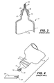
- Figure 4 is a further perspective view of container 2 of Figures 1 to 3 , now shown in the inverted position as would be typical during normal use to dispense a drop of control solution liquid from therein.
- Figure 4 includes many of the same features already described in relation to Figures 2 and 3 , and further includes a liquid droplet 22 shown emerging from outlet 14 in nozzle-shaped dispensing tip 8.
- a simplified example test strip 24 with a sample-receiving region 26 is also shown in Figure 4 .
- FIG. 1 to 4 when a patient intends to use the control solution cap 6 is first removed from container body 4, typically using a screw action or alternative such as a push-pull action for example. Container body 4 is then tilted so that the dispensing tip 8 is held several millimeters over the sample-receiving area 26 of a new test strip 24, such as the position depicted by Figure 4 . The user may then be required to apply a slight squeeze pressure to container body 4 to dispense a droplet 22 of the control solution out of the container 2 via outlet 14 that provides fluid communication with the exterior environment.
- Droplet 22 first emerges from outlet 14, then accumulates and subsequently suspends from the external surface area of dispensing tip 8 immediately surrounding outlet 14 due to the inherent capillary attraction of the liquid to the surface.
- This suspended, or hanging drop may be problematic because a single such drop may contain a relatively large volume of liquid that itself is problematic when a very small amount is desired to be dispensed.
- the user then brings the droplet 22 closer to the sample-receiving area 26 of the test strip 24.
- the fluid is taken up by capillary action into the reaction chamber of the test strip 24.
- Container 2 and the steps for dispensing a fluid such as control solution therefrom, is disadvantageous.
- the container is repeatedly opened over an extended period of time, thereby repeatedly exposing the control solution to contaminants in the air and on surfaces, such as the user's fingers for example, which can carry contaminants. Because the users of control solutions often have poor dexterity they may fumble the cap 6 and/or drop it, potentially further contaminating the control solution stored therein and causing erroneous test results. If it is determined that the control solution has become contaminated, the entirety of the control solution container must be thrown away, and a new container opened: adding to the cost to the user.
- control solution containers 2 can be problematic in that, because such a relatively large volume of the control solution is provided, the efficacy of the control solution may expire well before the majority of the control solution is used, which also adds to the cost of treating the patient.
- the shelf life of the control solution sealed within its original containment is usually about 1
- control solution fluid may also contain a small amount of surfactant to promote filling of the strip, addition of which may lower the surface tension causing the control solution to exhibit a tendency to creep up the side of the dispensing tip 8. This can make it more difficult for the user to accurately aim the control solution onto the receiving zone 26 of the test strip 24.
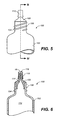
- Figure 5 is a side-plan view of an example fluid dispensing container 100 according to one embodiment of the present invention.
- the fluid dispensing container of Figure 5 includes a container body 102, a neck portion 104 with optional screw threads 106, a nozzle-shaped dispensing tip 108, a sleeve 110.
- Line B-B' in Figure 5 indicates the line of sight for the cross-section shown in Figure 6 .
- container 100 is anticipated to include a cap, similar to cap 6 shown in Figure 1 , which may optionally screw-fit onto neck portion 104 of container body 102 by means of threads 106, however alternative means of attaching a cap, such as a push-fit for example would be apparent to one skilled in the art.
- Figure 6 is a cross-section view through line B-B' of Figure 5 now showing an example embodiment of an internal structure of container 100, including a container body 102, a neck portion 104 with optional screw threads 106, a nozzle-shaped or tapered dispensing tip 108, a sleeve 110, a cavity area 112, a narrowly tapering frusto-conical internal channel 114, a small outlet 116 and a reservoir region 118 surrounding outlet 116. Reservoir 118 is formed by the boundaries of sleeve 110.
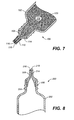
- Figure 7 is a similar cross-sectional view to that of Figure 6 , shown now in an inverted position as would be typical during normal use of container 100 in order to dispense a drop of control solution.
- Figure 7 includes many of the same elements described previously in relation to Figures 5 and 6 , as well as now showing the presence of a liquid 120 within cavity 112 of container body 102.
- a sleeve 110 such as a small piece of cylindrical tubing for example, to the dispensing tip 108. Provision of a sleeve 110 provides a reservoir 118 of fixed, predetermined volume making it easier to dispense the required amount of control solution. In addition, sleeve 110 may make control solution application easier for the user as it eliminates the need for a hanging drop, as discussed in reference to Figure 4 .
- the user needs only to gently squeeze the container in order to fill the reservoir region 118 around outlet 116 encompassed by the sleeve 110.
- the user may achieve this while holding the container 100 in the upright position as only a gentle squeeze to the container body 102 may be required to force the control solution through channel 114 and out via outlet 116.
- Use in a substantially upright position would allow the user to clearly see the control solution moving into and filling reservoir region 118.
- the user may tip container 100 into an almost inverted position as shown by Figure 7 , in order to dispense fluid 120 through the narrow tapering channel 114 and out via outlet 116, allowing the fluid to culminate in the reservoir region 118.
- the required volume of control solution fluid 120 would then be retained within the boundaries of sleeve 110 by capillary action.
- Sleeve 110 provides an expanded zone or reservoir region into which control solution 120 can fill and be held by capillary action, until such time that the user touches the end of the sleeve 110 onto the receiving portion 26 of a test strip 24.
- control solution 120 is taken up into the test strip 24 by capillary action.
- the reservoir region 118 is sized to hold only the volume of control solution required to fill the test strip. Once the test strip is in fluid communication with the control solution, sample fill is accomplished by capillary action thus reducing the likelihood of control solution being spilled.
- Figure 8 is a close-up cross sectional view through a container 200 according to a further embodiment of the present invention, including a container body 202, a neck portion 204 with optional screw threads 206, a one-piece dispensing tip 208, a narrow tapering channel 214 leading to an outlet 216 and an expanded reservoir region 218.
- Figure 8 provides a container 200 according to a further example embodiment of the present invention, suitable for use in the dispensing of a liquid such as control solution.
- dispenser tip 208 may be fabricated in one piece, thereby eliminating the additional or separate sleeve element 110 described in relation to Figures 5 to 7 .
- Dispenser tip 208 may be manufactured using appropriate technology e.g. injection molding. Such techniques also provide the advantage of mass production capability.
- the dispensing tip 208 of Figure 8 incorporates a narrow tapering internal channel 214 (similar to channel 114 of Figures 6 and 7 ) in fluid communication with the exterior environment by means of outlet 216.
- channel 214 may be annular, concentrically aligned with respect to the axis of fluid outlet 216.
- Application of pressure onto the external surfaces of container body 202 by a user causes fluid to emerge through outlet 216 and fill expanded reservoir region 218.
- the approximate dimensions of the expanded opening 218 may be in the region of 5 to 20 times greater than the dimensions of the narrow internal channel 214.
- expanded reservoir region 218 is designed to accommodate the volume of control solution required to fill the receiving region of a test strip in order for the user to perform a control solution test.
- Figure 8 shows square-shaped expanded reservoir region 218 with further detailed information provided in relation to Figures 9 and 10 .
- Figure 11 shows a similar, but rounded or semi-circular shaped expanded reservoir region 318.
- the example embodiments provided in Figures 8 and 11 are intended to be purely for illustration of embodiments of the present invention, and it will be apparent to one skilled in the art that any size and shape of expanded reservoir region is conceivable e.g. cylindrical, conical or hemispherical reservoirs for example, and are therefore intended to be included in the present invention.
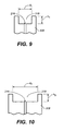
- Figure 9 is a close up cross-sectional view of the dispensing tip 208 of Figure 8 , including a fluid outlet 216, an expanded reservoir region 218 having a diameter d 1 and a height h 1 .
- Figure 10 is a close up cross-sectional view of the dispensing tip 208 of Figure 8 , including an outlet 216, an expanded reservoir region 218 having a diameter d 2 and a height h 2 .
- Figures 9 and 10 provide two example embodiments for a dispensing tip 208 of Figure 8 according to the present invention, the difference being in the relative diameter (d) and height (h) dimensions of the expanded reservoir region 218.
- Figure 9 shows an expanded reservoir region 218 which may have a diameter d 1 in the range of approximately 1 to 4mm, and more typically close to 2 mm, and a height h 1 in the range of approximately 1 to 2 mm, and more typically close to 1.6 mm.
- Such dimensions provide a volume capacity in the region of approximately 5 ⁇ L, and may be appropriately sized to contain smaller or larger volumes.
- the second embodiment of a reservoir region 218 provided in Figure 10 has a diameter d 2 in the range of approximately 1 to 5mm, and more typically close to 3mm, and a height h 2 in the range of approximately 0.5 to 1.5mm, or more typically close to 0.7mm.
- the dimensions of this second embodiment are also designed specifically to hold approximately 5 ⁇ L of control solution.
- dispensing tip provided in both Figures 9 and 10 would each hold a sufficient amount of control solution momentarily until the user is ready to proceed with the test and therefore touches the edge of the reservoir region 218 against the sample-receiving portion of a new test strip, causing the fluid to be taken into the reaction chamber of the test strip by capillary action.
- Reservoir region 218 holds the fluid momentarily, allowing the user to either bring the test strip into contact with the container in the upright position, or alternatively the user may prefer to invert the container to a suitable angle that is most comfortable for them to dispense the control solution onto the test strip. It will be apparent that a further advantage of the present invention is the ability to dispense control solution using an upright container.
- the volume of the expanded reservoir region of the present invention can be designed specifically, and may range from about 100 nL to 200 ⁇ L.
- the reservoir volume typically ranges from about 1 to 20 ⁇ L.
- the diameter of the expanded reservoir region may therefore be typically within the range from about 1 to 10mm, and more typically in the range from about 2 to 4mm.
- the depth of the expanded reservoir region (or alternatively 'height' as depicted by h 1 and h 2 in Figures 9 and 10 respectively) may be typically in the range from about 0.5 to 5mm, and more typically in the range from about 1 to 2mm. In cases in which a range of values is provided, it is understood that every intervening value, between the upper and lower limit of that range and any other stated or intervening value in that stated range is encompassed within the invention.
- Figure 11 is a cross sectional view through a container 300 according to a further embodiment of the present invention, including a container body 302, a neck portion 304 with (optional) screw threads 306, a dispensing tip portion 308, a narrow tapering internal channel 314 leading to a small fluid outlet 316 and an expanded reservoir region 318.
- Container 300 of Figure 11 is similar to container 200 of Figure 8 however there are some differences. The first difference being in the shape of the respective expanded reservoir regions surrounding the fluid-dispensing outlet.
- the embodiment of an expanded reservoir region 318 in Figure 11 is shown to be curved or hemi-spherical in shape, whereas the shape of expanded reservoir region 218 in the example embodiment of Figures 8 , 9 and 10 is shown to be primarily square or rectangular.
- dispensing tip provided by Figures 9, 10 and 11 are exemplary of suitable shapes in terms of volume and cross-section, however it would be apparent to one skilled in the art that any appropriate three-dimensional shape may be employed for the volume e.g. spheres, ellipsoids, paraboloids, cylinders, cones and the like, and any appropriate two-dimensional shape may be employed for the cross-sectional area, for example rectangles, triangles, ellipses, quadrilaterals such as parallelograms, polygons such as pentagons, and the like.
- Dispensing tip 208 of container 200 is shown as a separate moldable component, optionally manufactured separately from container body 202 and neck region 204, whereas dispensing tip 308 region of container 300 may be molded as one single element i.e . combined with container body 302 and neck region 304 for example. Molding the container 300 in a single piece may reduce the complexity of the container as well as the manufacturing and assembling processes. It would be apparent to a person of ordinary skill in the art that differences in the fabrication procedure for containers incorporating the present invention are conceivable and are therefore intended to be included herein.
- Figure 12 is a close up cross-sectional view 400 of an example embodiment of a cap 408 designed specifically to cooperate with an embodiment of a fluid dispensing tip 402 of the present invention, including a fluid outlet 404, an expanded reservoir region 406 having a diameter d 3 and a height h 3 , a cap internal protrusion 410 having a corresponding depth p 3 .
- Figure 13 is a close up cross-sectional view 500 of a further example embodiment of a cap 508 designed specifically to cooperate with an embodiment of a dispensing tip 502 of the present invention, including a fluid outlet 504, an expanded reservoir region 506 being of a cone-shape with a base diameter d 4 and a height h 4 , a cap internal protrusion 510 having a corresponding depth p 4 .
- Figures 12 and 13 show example embodiments of a dispensing tip design according to the present invention, now incorporating a complimentary feature in the container cap (items 410 and 510 respectively) designed specifically to seal the tip opening, as well as ensuring the container is fluid-tight during transportation and providing reliable storage.
- the cap protrusions 410, 510 may have a male-female structural cooperating relationship with the dispensing tip portions 402, 502 respectively in order to provide a reliable seal.
- internal protrusions 410 and 510 are specifically designed to interlock with the receiving portions, expanded reservoir regions 406 and 506 respectively, of the cooperating dispensing tip.
- the expanded reservoir regions 406 and 506 are sized and shaped accordingly to accept protrusions 410, 510.
- Figure 12 shows that the size and shape of expanded region 406 is not only designed specifically to hold an appropriate volume of control solution until the user is ready to apply it to a test sensor, but additionally the size and shape of expanded region 406 cooperates with internal protrusion 410 to provide a means for ensuring a reliable and trustworthy seal, thereby virtually eliminating the possibility of any control solution leaking out of the container while not in use.
- Depth p 3 of internal protrusion cooperates with height h 3 of expanded reservoir region 406, and the diameter d 3 of reservoir region 406 also cooperates with the corresponding diameter of the internal protrusion 410. Therefore, when the container of control solution is not being used, cap 408 can be fixed upon the container body, making contact primarily with the dispensing tip portion 402 thereof. Internal protrusion 410 fits snuggly within reservoir region 406 thereby forming a reliable seal over fluid outlet 404.
- Figure 13 shows a depth p 4 of a cone-shaped internal protrusion 510 that corresponds with the height h 4 of reservoir region 506. Therefore, when a user attaches cap 508 onto their container of control solution at dispensing tip 502, protrusion 510 is received by reservoir region 506 and forms a reliable seal across fluid outlet 504.
- Figures 12 and 13 show exemplary embodiments of container caps incorporating specific designs of sealing feature.
- the present invention includes devices for containing and dispensing liquid solutions.
- the liquid solutions may be any type of agent, reagent or control solution. Because there are wide variety of types of liquids used in various types of applications and settings, it is beyond the scope of this disclosure to list all possible liquids that may be used with the systems of the present invention. However, the subject systems may be used in any applications requiring single-doses of a liquid for frequent or infrequent use.
- the liquid is a control solution for the performance evaluation of a system for measuring analyte concentration in a sample of physiological fluid. Examples of such control solutions are disclosed in U.S. Patent Nos. 5,187,100 and 5,605,837 incorporated herein in their entireties.
- the present invention provides many advantages, including the increased ease of sample volume control and hence application thereof giving the user added confidence in the control solution testing procedure. It is also an aim of the dispensing tip of the present invention to minimize any sample spillage or fluid migration up the side of the dispensing tip by only providing a volume of control solution that is close to the required volume. Furthermore the volume of fluid is retained at least momentarily localized in the expanded region of the dispensing tip to help ensure adequate sample volume each time a control solution test is performed.
- the example embodiments of a fluid-dispensing tip facilitate the user in aiming the sample onto the sample-receiving region of the test sensor. Improved sample application also virtually eliminates the need to clean up any accidental spills.
- the fluid-dispensing tip of the present invention also minimizes the dexterity requirement of a user, easing the control solution testing procedure.
- the cooperating cap design ensures that the container remains fluid tight when not in use and during transportation and storage.
- a control solution container incorporating a dispensing tip of the present invention may also reduce the risk of contamination of unused control solution, which in turn provides a more reliable measurement system and may additionally be more cost effective to the user by maximizing the shelf life. Contaminated control solution may generate inaccurate results, and should be discarded.
Landscapes
- Engineering & Computer Science (AREA)
- Mechanical Engineering (AREA)
- Health & Medical Sciences (AREA)
- Clinical Laboratory Science (AREA)
- Chemical & Material Sciences (AREA)
- Chemical Kinetics & Catalysis (AREA)
- Closures For Containers (AREA)
- Containers And Packaging Bodies Having A Special Means To Remove Contents (AREA)
- Medical Preparation Storing Or Oral Administration Devices (AREA)
- Devices For Use In Laboratory Experiments (AREA)
Applications Claiming Priority (1)
| Application Number | Priority Date | Filing Date | Title |
|---|---|---|---|
| US98133007P | 2007-10-19 | 2007-10-19 |
Publications (1)
| Publication Number | Publication Date |
|---|---|
| EP2050501A1 true EP2050501A1 (fr) | 2009-04-22 |
Family
ID=40276143
Family Applications (2)
| Application Number | Title | Priority Date | Filing Date |
|---|---|---|---|
| EP08839491A Withdrawn EP2214831A1 (fr) | 2007-10-19 | 2008-10-16 | Embout de distribution de liquide avec réservoir |
| EP08253380A Withdrawn EP2050501A1 (fr) | 2007-10-19 | 2008-10-17 | Embout de distribution de liquide avec réservoir |
Family Applications Before (1)
| Application Number | Title | Priority Date | Filing Date |
|---|---|---|---|
| EP08839491A Withdrawn EP2214831A1 (fr) | 2007-10-19 | 2008-10-16 | Embout de distribution de liquide avec réservoir |
Country Status (6)
| Country | Link |
|---|---|
| US (1) | US20090101681A1 (fr) |
| EP (2) | EP2214831A1 (fr) |
| JP (2) | JP2009102070A (fr) |
| KR (1) | KR20100085111A (fr) |
| CN (2) | CN101903106A (fr) |
| WO (1) | WO2009052243A1 (fr) |
Families Citing this family (6)
| Publication number | Priority date | Publication date | Assignee | Title |
|---|---|---|---|---|
| US7886941B2 (en) * | 2005-04-25 | 2011-02-15 | Meadwestvaco Calmar Inc. | Dispenser having air tight spout |
| KR101247688B1 (ko) * | 2010-12-31 | 2013-04-01 | 나성식 | 액체용기 |
| JP2013214355A (ja) * | 2012-03-30 | 2013-10-17 | Equos Research Co Ltd | リチウムイオン電池用正極 |
| EP3034428B1 (fr) * | 2014-12-19 | 2017-07-19 | SHB GmbH | Bouchon de dosage pour un flacon de dosage |
| EP3477307B1 (fr) * | 2017-10-24 | 2020-07-22 | F. Hoffmann-La Roche AG | Dispositif de pipettage et système de positionnement de dispositif de pipettage |
| US10723526B1 (en) * | 2019-03-29 | 2020-07-28 | Chubby Gorilla, Inc. | Bottle and cap arrangement |
Citations (5)
| Publication number | Priority date | Publication date | Assignee | Title |
|---|---|---|---|---|
| US1662682A (en) * | 1926-03-29 | 1928-03-13 | Lloyd John Uri | Medicine dropper or syringe |
| EP0362911A1 (fr) * | 1988-09-01 | 1990-04-11 | Merck & Co. Inc. | Bouteille pour dispenser de manière contrôlable un liquide goutte à goutte |
| US5187100A (en) | 1990-05-29 | 1993-02-16 | Lifescan, Inc. | Dispersion to limit penetration of aqueous solutions into a membrane |
| US5605837A (en) | 1996-02-14 | 1997-02-25 | Lifescan, Inc. | Control solution for a blood glucose monitor |
| WO2002102514A1 (fr) * | 2001-06-19 | 2002-12-27 | B.C. Cancer Agency | Distributeur de microvolume de liquide conçu pour des micro-reseaux et procedes associes |
Family Cites Families (16)
| Publication number | Priority date | Publication date | Assignee | Title |
|---|---|---|---|---|
| US1698340A (en) * | 1929-01-08 | Liquid dropper | ||
| US2665826A (en) * | 1949-09-13 | 1954-01-12 | Merck & Co Inc | Adjustable spout and cap device for the sealing and dropwise dispensing of fluids |
| DE2030196A1 (de) * | 1970-06-19 | 1971-12-23 | Henkel & Cie GmbH, 4000 Düsseldorf | Verschluß für Klebstoffbehälter |
| DE2054667A1 (de) * | 1970-11-06 | 1972-05-10 | Henkel & Cie. GmbH, 4000 Düsseldorf | Verschluß für Klebstoffbehälter |
| US3945381A (en) * | 1974-10-18 | 1976-03-23 | Silver Industries, Inc. | Eye drop dispenser and cup |
| US4526490A (en) * | 1983-08-29 | 1985-07-02 | Dentsply Research & Development Corp. | Dispenser for flowable material |
| US5012496A (en) * | 1989-11-07 | 1991-04-30 | Acumetric, Inc. | Drop counting system |
| US5059188A (en) * | 1990-03-28 | 1991-10-22 | Goddard Larry C | Eye dropper attachment |
| US5373964A (en) * | 1993-06-23 | 1994-12-20 | Moore; Sidney D. | Eyedrop dispenser with focusing liquid lens |
| US6129248A (en) * | 1998-09-18 | 2000-10-10 | Hagele; James | Precision release tip for medicinal liquid dropper |
| CN2379315Y (zh) * | 1999-06-16 | 2000-05-24 | 复旦大学 | 微量液体分配器笔头 |
| FR2816600B1 (fr) * | 2000-11-13 | 2003-03-21 | Michel Faurie | Dispositif distributeur de liquides goutte a goutte |
| WO2004013009A1 (fr) * | 2002-08-06 | 2004-02-12 | Cohen, Ben, Z. | Flacon compte-gouttes et accessoires associes |
| DE102004040099A1 (de) * | 2004-08-18 | 2006-02-23 | Voco Gmbh | Lager-Dosier-System und Verfahren zum Applizieren einer fließfähigen Substanz |
| US20060129113A1 (en) * | 2004-12-09 | 2006-06-15 | James Merrick | Eye drop applicator |
| US7325708B2 (en) * | 2005-01-14 | 2008-02-05 | Rory Barber | Ocular positioning droplet dispensing device with a recessed dispensing orifice |
-
2008
- 2008-10-10 US US12/248,935 patent/US20090101681A1/en not_active Abandoned
- 2008-10-16 JP JP2008267605A patent/JP2009102070A/ja active Pending
- 2008-10-16 WO PCT/US2008/080092 patent/WO2009052243A1/fr not_active Ceased
- 2008-10-16 JP JP2010530096A patent/JP2011501722A/ja active Pending
- 2008-10-16 EP EP08839491A patent/EP2214831A1/fr not_active Withdrawn
- 2008-10-16 KR KR1020107010829A patent/KR20100085111A/ko not_active Withdrawn
- 2008-10-16 CN CN2008801214693A patent/CN101903106A/zh active Pending
- 2008-10-17 EP EP08253380A patent/EP2050501A1/fr not_active Withdrawn
- 2008-10-20 CN CNA200810172994XA patent/CN101430337A/zh active Pending
Patent Citations (5)
| Publication number | Priority date | Publication date | Assignee | Title |
|---|---|---|---|---|
| US1662682A (en) * | 1926-03-29 | 1928-03-13 | Lloyd John Uri | Medicine dropper or syringe |
| EP0362911A1 (fr) * | 1988-09-01 | 1990-04-11 | Merck & Co. Inc. | Bouteille pour dispenser de manière contrôlable un liquide goutte à goutte |
| US5187100A (en) | 1990-05-29 | 1993-02-16 | Lifescan, Inc. | Dispersion to limit penetration of aqueous solutions into a membrane |
| US5605837A (en) | 1996-02-14 | 1997-02-25 | Lifescan, Inc. | Control solution for a blood glucose monitor |
| WO2002102514A1 (fr) * | 2001-06-19 | 2002-12-27 | B.C. Cancer Agency | Distributeur de microvolume de liquide conçu pour des micro-reseaux et procedes associes |
Also Published As
| Publication number | Publication date |
|---|---|
| KR20100085111A (ko) | 2010-07-28 |
| CN101903106A (zh) | 2010-12-01 |
| WO2009052243A1 (fr) | 2009-04-23 |
| US20090101681A1 (en) | 2009-04-23 |
| JP2011501722A (ja) | 2011-01-13 |
| JP2009102070A (ja) | 2009-05-14 |
| EP2214831A1 (fr) | 2010-08-11 |
| CN101430337A (zh) | 2009-05-13 |
Similar Documents
| Publication | Publication Date | Title |
|---|---|---|
| US20110130740A1 (en) | Medication Bottle for Use with Oral Syringe | |
| US9656258B2 (en) | Pipette | |
| US5874048A (en) | Spotting tip | |
| US20090101681A1 (en) | Liquid Dispensing Tip With Reservoir | |
| US5972297A (en) | Ball and socket closure for specimen collection container incorporating a septum | |
| JPH1111513A (ja) | 少量の流体を分与するための分与装置 | |
| US4925065A (en) | Dispensing apparatus | |
| GB2100237A (en) | Liquid dispensing bottle | |
| US8841127B2 (en) | Methods and devices for sample collection, treatment and dispensing | |
| EP0928969A2 (fr) | Appareil de test de reaction en forme de cÔne tronqué creux | |
| CA2097283C (fr) | Distributeur de liquide tubulaire | |
| US3881527A (en) | Bulb-operated pipet | |
| US20070086924A1 (en) | Pipette with contamination indicator | |
| US5125278A (en) | Volumetric pipette | |
| EP2606870B1 (fr) | Perfectionnements apportés et ayant trait à la distribution de liquides | |
| CA2448803C (fr) | Limitation de l'evaporation d'une reserve de fluide | |
| AU2011205088A1 (en) | System and method for dispensing fluid from a container and into a fluid receptacle | |
| US11415578B2 (en) | Biosensor platform for rapid diagnostic testing | |
| WO2005030033A2 (fr) | Dispositif d'analyse d'echantillon de fluide | |
| US20090105664A1 (en) | Syringe Adapter | |
| JPH01111656A (ja) | 標準液等の容器 | |
| WO2025078294A1 (fr) | Kit d'élution, kit analytique et procédé d'élution et d'analyse d'un échantillon biologique | |
| HK1129624A (en) | Syringe adapter | |
| JPH0431739B2 (fr) | ||
| JP2003075306A (ja) | 分注器具 |
Legal Events
| Date | Code | Title | Description |
|---|---|---|---|
| PUAI | Public reference made under article 153(3) epc to a published international application that has entered the european phase |
Free format text: ORIGINAL CODE: 0009012 |
|
| AK | Designated contracting states |
Kind code of ref document: A1 Designated state(s): AT BE BG CH CY CZ DE DK EE ES FI FR GB GR HR HU IE IS IT LI LT LU LV MC MT NL NO PL PT RO SE SI SK TR |
|
| AX | Request for extension of the european patent |
Extension state: AL BA MK RS |
|
| AKX | Designation fees paid | ||
| REG | Reference to a national code |
Ref country code: DE Ref legal event code: 8566 |
|
| STAA | Information on the status of an ep patent application or granted ep patent |
Free format text: STATUS: THE APPLICATION IS DEEMED TO BE WITHDRAWN |
|
| 18D | Application deemed to be withdrawn |
Effective date: 20091023 |