EP2050565A2 - Dispositif et procédé de préparation de moules de flexographie - Google Patents
Dispositif et procédé de préparation de moules de flexographie Download PDFInfo
- Publication number
- EP2050565A2 EP2050565A2 EP08015898A EP08015898A EP2050565A2 EP 2050565 A2 EP2050565 A2 EP 2050565A2 EP 08015898 A EP08015898 A EP 08015898A EP 08015898 A EP08015898 A EP 08015898A EP 2050565 A2 EP2050565 A2 EP 2050565A2
- Authority
- EP
- European Patent Office
- Prior art keywords
- flexographic printing
- imaged
- printing cylinder
- pin
- sleeves
- Prior art date
- Legal status (The legal status is an assumption and is not a legal conclusion. Google has not performed a legal analysis and makes no representation as to the accuracy of the status listed.)
- Withdrawn
Links
Images

Classifications
-
- B—PERFORMING OPERATIONS; TRANSPORTING
- B41—PRINTING; LINING MACHINES; TYPEWRITERS; STAMPS
- B41C—PROCESSES FOR THE MANUFACTURE OR REPRODUCTION OF PRINTING SURFACES
- B41C1/00—Forme preparation
- B41C1/02—Engraving; Heads therefor
- B41C1/04—Engraving; Heads therefor using heads controlled by an electric information signal
- B41C1/05—Heat-generating engraving heads, e.g. laser beam, electron beam
-
- B—PERFORMING OPERATIONS; TRANSPORTING
- B41—PRINTING; LINING MACHINES; TYPEWRITERS; STAMPS
- B41C—PROCESSES FOR THE MANUFACTURE OR REPRODUCTION OF PRINTING SURFACES
- B41C1/00—Forme preparation
- B41C1/18—Curved printing formes or printing cylinders
- B41C1/182—Sleeves; Endless belts
-
- B—PERFORMING OPERATIONS; TRANSPORTING
- B41—PRINTING; LINING MACHINES; TYPEWRITERS; STAMPS
- B41F—PRINTING MACHINES OR PRESSES
- B41F13/00—Common details of rotary presses or machines
- B41F13/08—Cylinders
- B41F13/20—Supports for bearings or supports for forme, offset, or impression cylinders
Definitions
- the invention relates to a method for providing imaged and / or non-imaged flexographic printing plates, in particular flexographic printing cylinders and / or flexographic printing sleeves (sleeves).
- the invention relates to a device for providing imaged and / or non-imaged flexographic printing plates, in particular flexographic printing cylinders and / or flexographic printing sleeves (sleeves).
- WO 00/13839 is a device for direct laser engraving of printing plates, in particular also of flexographic printing plates, preferably flexographic printing cylinders, disclosed, so that flexographic printing forms can be imaged.
- the invention has for its object to show ways to increase the productivity of the aforementioned technical genres.
- This object is achieved according to the invention in process view, that an imaging device for imaging a flexographic printing plate is automatically loaded with to be imaged flexographic printing plates.
- an imaging device can in principle a device of the type from the WO 00/13839 known device can be used. According to the invention, the latter is automatically charged with flexographic printing plates with a corresponding charging device in order to increase their throughput and thus their productivity.
- the number of engraving tools could be increased and / or multiple imaging devices could be used and loaded.
- a flexographic printing cylinder delivered for the imaging device can also be automatically detected and processed, it is provided according to a development of the invention that a flexographic printing cylinder is automatically rotationally driven, for which purpose it may preferably be provided that a flexographic printing cylinder is clamped by means of cones which can be inserted in frontal openings of the flexographic printing cylinder becomes.
- This flexographic printing cylinder can be a flexographic printing cylinder, as it is later used in a printing press, but it can also be a special cylinder for engraving be provided with the sleeve to beimaged, so that the illustrated sleeve later on another, for the pressure provided cylinder is wound.
- An insertion into the imaging device by means of a crane from above is preferably facilitated by the fact that at least in one of the conical areas a pin of a flexographic printing cylinder is supported in a retraction or extension of the cone, which could be realized, for example, with a tray-like, preferably trough-shaped tray ,
- Another development of the invention provides that the rotational position of a flexographic printing cylinder is detected by a groove detection.
- a flexographic printing sleeve mounting station is provided on which sleeves can be pulled up and down on or from a mandrel, the mandrel preferably being clamped on one side in the flexographic printing sleeve mounting station.
- a next development of the invention provides that a finished imaged flexographic printing plate is washed by means of an automatically loadable washer.
- non-imaged and / or partially imaged and / or imaged flexographic printing plates in particular flexographic printing cylinders, can be stored in a bearing, preferably also flexographic printing sleeves and / or spacer sleeves and / or mandrels.
- a further development of the method according to the invention is characterized in that at least some workstations are arranged to form a working line.
- some workstations are preferably connected to one another via a crane work path.
- a workflow in particular via different workstations, is controlled by means of a job ticket created and processed in an electronic data processing device.
- a job ticket station can also be connected to a line controller for in-line workstations and / or to a RIP station (raster image processor).
- a job ticket can also contain all the data that is entered in manual mode in the RIP configuration as well as at the operating terminals of the engraver and the washer. Status information can also be enrolled to enable job tracking and job scheduling.
- the device according to the invention is characterized by a clamping device, with the flexographic printing cylinder are automatically driven to rotate driven, the clamping device preferably in frontal openings Having a flexoprinting cylinder retractable cones.
- Loading or loading the device according to the invention with a crane from above is preferably facilitated by the fact that at least one of the conical regions is provided with a supporting device supporting a journal of a flexographic printing cylinder during retraction or extension of the cone, preferably in the form of a tray over the associated cone.
- the support device may have a receiving trough for inserting the pin.
- This storage option according to the invention also secures the flexographic printing cylinder before the flexographic printing cylinder is clamped and after it has been released, preferably positionally accurate for threading out and in the cones, in particular also when the cones enter the respective ends of the flexographic printing cylinder at different times.
- the support device has a claw-like stop for the rear grip of a recess in the pin.
- This has the advantage that with the help of the rear grip of the flexographic printing cylinder, if necessary, forcibly released from the cones, even if, for example, a cone should sit too tight in an insertion hole. Then holds because of the extension movement asymmetrically the claw in the region of the already released cone, the cylinder and sets the other cone sufficient resistance, through which then the other cone finally dissolves from the flexographic printing cylinder.
- the same recess in the respective journal of the flexographic printing cylinder can also be used preferably for holding and locking the flexographic printing cylinder in the above-mentioned flexographic printing sleeve mounting station.
- the support device may have at least one bearing roller with a roller axis oriented parallel to the journal axis in order to center the journal and / or to keep it in a lunette-like manner.
- the device according to the invention may comprise a groove detection device for detecting the rotational position of a flexographic printing cylinder, as for gravure gravure cylinder in principle in optionally comparable manner from the DE 101 07 192 is known.
- the device according to the invention can have a flexographic printing sleeve mounting station on which sleeves can be pulled up or down on or from a mandril or a so-called air cylinder, wherein this comprises a clamping device for the unilateral clamping of a mandrel and / or flexographic printing cylinder or air cylinder could include.
- the clamping device could have a kind of coupling sleeve, with which the pin is free of forces lockable, preferably possibly including the inclusion of the aforementioned recess of the pin.
- air cylinder as used in part, is intended to indicate that drawing or withdrawing of a spacer or sleeve uses compressed air which, for example, flows radially outward and / or axially to the air cylinder to produce an air cushion on which the corresponding sleeve better can glide through which it can be expanded but in particular.
- it could also be provided in particular in the assembly station to redirect such air, for example by means of a kind of cover, so that it can be used optionally for a spacer or a sleeve.
- a development of the device according to the invention provides that a support device for a flexographic printing cylinder can be pivoted about a vertical axis, so that the flexographic printing cylinder is accessible for a more convenient installation, in particular if the assembly station is integrated into an imaging device itself, which is quite possible.
- the device according to the invention or a working line can have a washer which can be automatically charged with a ready-imaged flexographic printing plate, which is preferably equipped with an automatically opening and closing lid, in particular a liquid-tight closing lid. Remains of material after imaging, especially after a direct, ablative laser engraving, can be automatically washed out in order to prepare the imaged flexographic printing plate ready for printing.
- a bearing may preferably be provided for non-imaged and / or partially imaged and / or imaged flexographic printing plates, in particular flexographic printing cylinders, which is designed, for example, as a flat rack, and a bearing may be provided for flexographic printing sleeves and / or spacer sleeves and / or mandrels be, which is designed for example as a parking area.
- the concept according to the invention can be distinguished by the fact that at least some workstations are arranged to form a working line, wherein the bearings could be wholly or partly included.
- some workstations could be connected to each other via a crane work path, which is designed as an overhead crane, for example.
- the workstations and work steps are controlled logistically and in their sequence, including, for example, with respect to an execution schedule, in particular by a control device for controlling a work process, in particular via different workstations, by means of an electronic data processing device processed job tickets.
- the control device can preferably also be connected or coupled to a line control for workstations arranged in a line and / or to an RIP station (raster image processor).
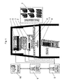
- Fig. 1 shows a schematic perspective view of a working line according to the invention.
- An engraving machine 1 for flexographic printing cylinder 2 is associated with a washer 3, in which a finished engraved flexographic printing cylinder 2 can be washed out for its readiness for printing.
- Both the engraving machine 1 and the washer 3 are automatically supplied with a flexographic printing cylinder.
- a crane 4 is provided which can be moved over a large part of the working line.
- the washer is also provided with an automatically opening and closing lid 5.
- a flexographic printing cylinder 2 is automatically clamped and releasable, which with Fig. 2 is explained in more detail.
- a flat storage rack 6 for finished engraved or semi-finished flexographic printing cylinders with or without sleeve and a shelf storage 7 for sleeves and spacer sleeves (spacer) are also provided.
- the work line is assigned a line controller 8, a job ticket station 9 and a RIP station 10, which work by means of electronic data processing.
- an assembly station 11 is placed, in which a sleeve can be pulled onto a flexographic printing cylinder 2 or withdrawn from this.
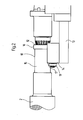
- Fig. 2 1 shows a side view of a clamping device of an engraving machine 1 for one end of a flexographic printing cylinder 2.
- the clamping device comprises a clamping cone 12, which enters an open end side of the flexographic printing cylinder 2, to hold and stretch it.
- a trough-shaped storage tray 14 for a pin 15 of the flexographic printing cylinder 2 is arranged projecting on a cantilever 13.
- the pin 15 is also safe when the cone 12 is not yet retracted into it to hold it or when the pin 15 has been released again from the cone 12 for removal of the flexographic printing cylinder 2.
- the pin 15 can be safely and easily placed in particular with the crane 4 or lifted from this.
- the other end of the flexographic printing cylinder 2 is clamped mirror-symmetrically.
- Fig. 3 shows an assembly station 11 in a schematic, perspective view. It is important that one end of the flexographic printing cylinder 2 can be free, while the flexographic printing cylinder is held securely on the other. About the free end then a spacer sleeve and / or a sleeve can be mounted on a mandril of a flexographic printing cylinder 2 or deducted from it, the expansion of the sleeves and their axial sliding can be supported by compressed air supply.
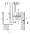
- Fig. 4 shows in section a locking device for a mounting station 11, in which a pin 15 of a flexographic printing cylinder 2 can be securely locked.
- a locking block 19 can be pushed back and forth in the direction of a double arrow 20, which runs parallel to the axis of the flexographic printing cylinder 2, for locking and unlocking.
- This displacement 20 takes place on a fixed base 21 on which the crane 4, the pin 15 can hang up first.
- a stop 22 of the pad 21 engages in the recess 18 of the pin 15 and limits its range of motion axially.
- the locking block 19 is displaced into its locking position (in the drawing to the right), it engages over the pin 15. If the other end of the flexographic printing cylinder 2 now comes free, the locked pin 15 is already jammed by the weight of the flexographic printing cylinder 2 itself and the flexographic printing cylinder 2 is kept safe at one end.
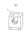
- Fig. 5 shows the locking block 19 according to Fig. 4 in a perspective view.
Landscapes
- Engineering & Computer Science (AREA)
- Manufacturing & Machinery (AREA)
- Mechanical Engineering (AREA)
- Physics & Mathematics (AREA)
- Optics & Photonics (AREA)
- Plasma & Fusion (AREA)
- Manufacture Or Reproduction Of Printing Formes (AREA)
- Printing Plates And Materials Therefor (AREA)
Applications Claiming Priority (1)
| Application Number | Priority Date | Filing Date | Title |
|---|---|---|---|
| DE102007050339A DE102007050339B4 (de) | 2007-10-18 | 2007-10-18 | Vorrichtung zur Bereitstellung von bebilderten oder von bebilderten und unbebilderten Flexodruckzylindern und / oder Flexodruckhülsen |
Publications (1)
| Publication Number | Publication Date |
|---|---|
| EP2050565A2 true EP2050565A2 (fr) | 2009-04-22 |
Family
ID=40202874
Family Applications (1)
| Application Number | Title | Priority Date | Filing Date |
|---|---|---|---|
| EP08015898A Withdrawn EP2050565A2 (fr) | 2007-10-18 | 2008-09-10 | Dispositif et procédé de préparation de moules de flexographie |
Country Status (3)
| Country | Link |
|---|---|
| US (1) | US20090101029A1 (fr) |
| EP (1) | EP2050565A2 (fr) |
| DE (1) | DE102007050339B4 (fr) |
Citations (3)
| Publication number | Priority date | Publication date | Assignee | Title |
|---|---|---|---|---|
| EP0787597A2 (fr) | 1996-01-31 | 1997-08-06 | POLYWEST KUNSTSTOFFTECHNIK Saueressig & Partner GmbH & Co. KG | Manchon pour cylindre d'impression en creux, procédé pour la fabrication de ce cylindre et procédé de fonctionnement de l'appareil pour la fabrication |
| WO2000013839A1 (fr) | 1998-09-08 | 2000-03-16 | Heidelberger Druckmaschinen Aktiengesellschaft | Source de rayonnement laser |
| DE10107192A1 (de) | 2001-02-16 | 2002-09-26 | Heidelberger Druckmasch Ag | Verfahren zur Gravur von Druckzylindern |
Family Cites Families (6)
| Publication number | Priority date | Publication date | Assignee | Title |
|---|---|---|---|---|
| US5583647A (en) * | 1993-05-05 | 1996-12-10 | Ohio Electronic Engravers, Inc. | Cylinder support apparatus and method for use in an engraver |
| FR2751437B1 (fr) * | 1996-07-19 | 1998-09-04 | Photomeca Egg | Procede pour la confection automatique de manchons d'impression |
| DE19921139A1 (de) * | 1999-05-07 | 2000-11-09 | Heidelberger Druckmasch Ag | Verfahren und Vorrichtung zum Laden von Druckzylindern |
| JP2001201848A (ja) * | 2000-01-17 | 2001-07-27 | Think Laboratory Co Ltd | フレキソ製版工場 |
| DE10050750A1 (de) * | 2000-10-13 | 2002-04-25 | Kaspar Walter Gmbh & Co Kg | Kompakte Bearbeitungsanlage für Druckzylinder |
| DE50200595D1 (de) * | 2002-02-26 | 2004-08-12 | Rsd Technik Gmbh | Gravier- oder Druckmaschine |
-
2007
- 2007-10-18 DE DE102007050339A patent/DE102007050339B4/de not_active Expired - Fee Related
-
2008
- 2008-09-10 EP EP08015898A patent/EP2050565A2/fr not_active Withdrawn
- 2008-10-08 US US12/247,481 patent/US20090101029A1/en not_active Abandoned
Patent Citations (3)
| Publication number | Priority date | Publication date | Assignee | Title |
|---|---|---|---|---|
| EP0787597A2 (fr) | 1996-01-31 | 1997-08-06 | POLYWEST KUNSTSTOFFTECHNIK Saueressig & Partner GmbH & Co. KG | Manchon pour cylindre d'impression en creux, procédé pour la fabrication de ce cylindre et procédé de fonctionnement de l'appareil pour la fabrication |
| WO2000013839A1 (fr) | 1998-09-08 | 2000-03-16 | Heidelberger Druckmaschinen Aktiengesellschaft | Source de rayonnement laser |
| DE10107192A1 (de) | 2001-02-16 | 2002-09-26 | Heidelberger Druckmasch Ag | Verfahren zur Gravur von Druckzylindern |
Also Published As
| Publication number | Publication date |
|---|---|
| DE102007050339A1 (de) | 2009-04-23 |
| US20090101029A1 (en) | 2009-04-23 |
| DE102007050339B4 (de) | 2009-10-08 |
Similar Documents
| Publication | Publication Date | Title |
|---|---|---|
| EP0639452B1 (fr) | Machine d'impression avec au moins un cylindre interchangeable, en particulier un cylindre imprimeur interchangeable, ou avec une plaque d'impression interchangeable | |
| DE69403065T2 (de) | Druckmaschine mit austauschbaren teilen sowie vorrichtung und verfahren zum austausch von teilen in einer solchen druckmaschine | |
| DE3902470C2 (fr) | ||
| DE102004037253B4 (de) | Sleevewechselsystem | |
| DE202004021890U1 (de) | Druckmaschine mit mindestens einem Formzylinder und mit einem Druckformmagazin | |
| EP0290853A2 (fr) | Palier pour cylindre de groupe d'impression | |
| DE10314297B4 (de) | Verfahren und Vorrichtung zum Wechseln mindestens eines Zylinders an einer Druck- oder Lackiermaschine | |
| WO2008077730A2 (fr) | Dispositifs comprenant plusieurs compartiments de stockage situés respectivement à distance les uns des autres | |
| EP1882587A2 (fr) | Machine d'impression | |
| CH694986A5 (de) | Einrichtung zur Herstellung von Druckformen. | |
| DE69402653T2 (de) | Verfahren zum Austauschen von Stanzwerkzeugen in einer Plattenpresse sowie Vorrichtung zur Durchführung des Verfahrens | |
| DE102009039050A1 (de) | Rollenrotationsdruckmaschine | |
| DE10314343B4 (de) | Vorrichtung zum Speichern eines an einem Zylinder einer Druckmaschine auszutauschenden Aufzugs | |
| EP2468507B1 (fr) | Dispositif de transmission pour un changement de film. | |
| DE102005046088A1 (de) | Vorrichtung zur Bewerktstlligung eines Walzenwechsels, sowie hiermit ausgestattete Druckmaschine an sich | |
| DE102007050339B4 (de) | Vorrichtung zur Bereitstellung von bebilderten oder von bebilderten und unbebilderten Flexodruckzylindern und / oder Flexodruckhülsen | |
| DE102008005798A1 (de) | Druckmaschine mit einer Vorrichtung zum Wechseln von Druckplatten | |
| DE10305956B4 (de) | Verfahren zum Wechseln von Druckhülsen in einer Druckmaschine | |
| CH695554A5 (de) | Einrichtung zur Herstellung von Druckformen. | |
| DE69506031T2 (de) | Wechselvorrichtung für die Werkzeuge einer Schneidvorrichtung | |
| DE3876431T2 (de) | Auswechselgeraet fuer freitragende walzen in walzgeruesten. | |
| EP1155836B1 (fr) | Dispositif pour amener une plaque d'impression à un cylindre porte-plaque d'une machine à imprimer | |
| DE202004011420U1 (de) | Automatische Vorrichtung für die Bewegung und den Transport von Druckmänteln | |
| DE102009045390B4 (de) | Mobiles Transportmittel zum Transport von mindestens einer einer Druckeinheit einer Druckmaschine zuzuführenden oder von dort abzuführenden Druckform | |
| DE10159393A1 (de) | Verfahren und Vorrichtung zur Einbringung und Ausbringung eines Druckformzylinders in eine oder aus einer Graviermaschine |
Legal Events
| Date | Code | Title | Description |
|---|---|---|---|
| PUAI | Public reference made under article 153(3) epc to a published international application that has entered the european phase |
Free format text: ORIGINAL CODE: 0009012 |
|
| AK | Designated contracting states |
Kind code of ref document: A2 Designated state(s): AT BE BG CH CY CZ DE DK EE ES FI FR GB GR HR HU IE IS IT LI LT LU LV MC MT NL NO PL PT RO SE SI SK TR |
|
| AX | Request for extension of the european patent |
Extension state: AL BA MK RS |
|
| STAA | Information on the status of an ep patent application or granted ep patent |
Free format text: STATUS: THE APPLICATION IS DEEMED TO BE WITHDRAWN |
|
| 18D | Application deemed to be withdrawn |
Effective date: 20110401 |