EP2050596A1 - Dispositif électronique d'alimenation en air - Google Patents
Dispositif électronique d'alimenation en air Download PDFInfo
- Publication number
- EP2050596A1 EP2050596A1 EP20080014327 EP08014327A EP2050596A1 EP 2050596 A1 EP2050596 A1 EP 2050596A1 EP 20080014327 EP20080014327 EP 20080014327 EP 08014327 A EP08014327 A EP 08014327A EP 2050596 A1 EP2050596 A1 EP 2050596A1
- Authority
- EP
- European Patent Office
- Prior art keywords
- compressed air
- pressure
- circuits
- valve
- service brake
- Prior art date
- Legal status (The legal status is an assumption and is not a legal conclusion. Google has not performed a legal analysis and makes no representation as to the accuracy of the status listed.)
- Granted
Links
Images
Classifications
-
- B—PERFORMING OPERATIONS; TRANSPORTING
- B60—VEHICLES IN GENERAL
- B60G—VEHICLE SUSPENSION ARRANGEMENTS
- B60G17/00—Resilient suspensions having means for adjusting the spring or vibration-damper characteristics, for regulating the distance between a supporting surface and a sprung part of vehicle or for locking suspension during use to meet varying vehicular or surface conditions, e.g. due to speed or load
- B60G17/02—Spring characteristics, e.g. mechanical springs and mechanical adjusting means
- B60G17/04—Spring characteristics, e.g. mechanical springs and mechanical adjusting means fluid spring characteristics
- B60G17/052—Pneumatic spring characteristics
- B60G17/0523—Regulating distributors or valves for pneumatic springs
-
- B—PERFORMING OPERATIONS; TRANSPORTING
- B60—VEHICLES IN GENERAL
- B60G—VEHICLE SUSPENSION ARRANGEMENTS
- B60G17/00—Resilient suspensions having means for adjusting the spring or vibration-damper characteristics, for regulating the distance between a supporting surface and a sprung part of vehicle or for locking suspension during use to meet varying vehicular or surface conditions, e.g. due to speed or load
- B60G17/015—Resilient suspensions having means for adjusting the spring or vibration-damper characteristics, for regulating the distance between a supporting surface and a sprung part of vehicle or for locking suspension during use to meet varying vehicular or surface conditions, e.g. due to speed or load the regulating means comprising electric or electronic elements
- B60G17/018—Resilient suspensions having means for adjusting the spring or vibration-damper characteristics, for regulating the distance between a supporting surface and a sprung part of vehicle or for locking suspension during use to meet varying vehicular or surface conditions, e.g. due to speed or load the regulating means comprising electric or electronic elements characterised by the use of a specific signal treatment or control method
- B60G17/0185—Resilient suspensions having means for adjusting the spring or vibration-damper characteristics, for regulating the distance between a supporting surface and a sprung part of vehicle or for locking suspension during use to meet varying vehicular or surface conditions, e.g. due to speed or load the regulating means comprising electric or electronic elements characterised by the use of a specific signal treatment or control method for failure detection
-
- B—PERFORMING OPERATIONS; TRANSPORTING
- B60—VEHICLES IN GENERAL
- B60T—VEHICLE BRAKE CONTROL SYSTEMS OR PARTS THEREOF; BRAKE CONTROL SYSTEMS OR PARTS THEREOF, IN GENERAL; ARRANGEMENT OF BRAKING ELEMENTS ON VEHICLES IN GENERAL; PORTABLE DEVICES FOR PREVENTING UNWANTED MOVEMENT OF VEHICLES; VEHICLE MODIFICATIONS TO FACILITATE COOLING OF BRAKES
- B60T17/00—Component parts, details, or accessories of power brake systems not covered by groups B60T8/00, B60T13/00 or B60T15/00, or presenting other characteristic features
- B60T17/002—Air treatment devices
- B60T17/004—Draining and drying devices
-
- B—PERFORMING OPERATIONS; TRANSPORTING
- B60—VEHICLES IN GENERAL
- B60T—VEHICLE BRAKE CONTROL SYSTEMS OR PARTS THEREOF; BRAKE CONTROL SYSTEMS OR PARTS THEREOF, IN GENERAL; ARRANGEMENT OF BRAKING ELEMENTS ON VEHICLES IN GENERAL; PORTABLE DEVICES FOR PREVENTING UNWANTED MOVEMENT OF VEHICLES; VEHICLE MODIFICATIONS TO FACILITATE COOLING OF BRAKES
- B60T17/00—Component parts, details, or accessories of power brake systems not covered by groups B60T8/00, B60T13/00 or B60T15/00, or presenting other characteristic features
- B60T17/02—Arrangements of pumps or compressors, or control devices therefor
-
- B—PERFORMING OPERATIONS; TRANSPORTING
- B60—VEHICLES IN GENERAL
- B60T—VEHICLE BRAKE CONTROL SYSTEMS OR PARTS THEREOF; BRAKE CONTROL SYSTEMS OR PARTS THEREOF, IN GENERAL; ARRANGEMENT OF BRAKING ELEMENTS ON VEHICLES IN GENERAL; PORTABLE DEVICES FOR PREVENTING UNWANTED MOVEMENT OF VEHICLES; VEHICLE MODIFICATIONS TO FACILITATE COOLING OF BRAKES
- B60T17/00—Component parts, details, or accessories of power brake systems not covered by groups B60T8/00, B60T13/00 or B60T15/00, or presenting other characteristic features
- B60T17/18—Safety devices; Monitoring
- B60T17/22—Devices for monitoring or checking brake systems; Signal devices
- B60T17/221—Procedure or apparatus for checking or keeping in a correct functioning condition of brake systems
-
- B—PERFORMING OPERATIONS; TRANSPORTING
- B60—VEHICLES IN GENERAL
- B60G—VEHICLE SUSPENSION ARRANGEMENTS
- B60G2400/00—Indexing codes relating to detected, measured or calculated conditions or factors
- B60G2400/50—Pressure
- B60G2400/51—Pressure in suspension unit
- B60G2400/512—Pressure in suspension unit in spring
- B60G2400/5122—Fluid spring
- B60G2400/51222—Pneumatic
-
- B—PERFORMING OPERATIONS; TRANSPORTING
- B60—VEHICLES IN GENERAL
- B60G—VEHICLE SUSPENSION ARRANGEMENTS
- B60G2500/00—Indexing codes relating to the regulated action or device
- B60G2500/02—Supply or exhaust flow rates; Pump operation
-
- B—PERFORMING OPERATIONS; TRANSPORTING
- B60—VEHICLES IN GENERAL
- B60G—VEHICLE SUSPENSION ARRANGEMENTS
- B60G2600/00—Indexing codes relating to particular elements, systems or processes used on suspension systems or suspension control systems
- B60G2600/02—Retarders, delaying means, dead zones, threshold values, cut-off frequency, timer interruption
-
- B—PERFORMING OPERATIONS; TRANSPORTING
- B60—VEHICLES IN GENERAL
- B60G—VEHICLE SUSPENSION ARRANGEMENTS
- B60G2600/00—Indexing codes relating to particular elements, systems or processes used on suspension systems or suspension control systems
- B60G2600/08—Failure or malfunction detecting means
Definitions
- the invention relates to an electronic air treatment system for equipped with an air suspension system vehicles according to the preamble of claim 1.
- an air compressor is known, from the output to supply the compressed air system leads a delivery line to an air dryer.
- the delivery line is branched on the output side of the air dryer in leading to at least two load circuits line branches.
- the pressure in the consumer circuits can be monitored by pressure sensors. It is provided an electronic control unit to which the pressure sensors are connected.
- the consumer circuits can be separated from the compressed air supply by a switchable from the programmable control electronics, lying in the respective delivery line branch locking member.
- the locking member is formed by an overflow valve, which are switchable by an additional actuating means in a position blocking the associated line branch.
- the actuating means may be a pneumatic, electromagnetic or electromechanical actuating means.
- a disadvantage of this known compressed air supply device is that for each overflow valve its own actuating means, for example. Solenoid valve, is provided for actuation.
- a pneumatic vehicle braking system comprising a compressor, at least one air consumer circuit, for example service brake circuits, a parking brake circuit, a low pressure auxiliary circuit and a high pressure circuit, the circuits having compressed air reservoirs and demand valves.
- a compressor Between the compressor and each consumption circuit is a first, closed in the ground state, electrically actuated valve and between the compressor and the auxiliary circuit, a second in the ground state open, electrically actuated valve.
- the valves are operated by an electronic control unit.
- the output ports of the first valves of the air consumer circuits are connected via check valves to the output port of the second normally open valve.
- the corresponding valve is opened by the control unit, whereby the air requirement is covered by the compressor, while the second valve of the auxiliary circuit is closed. Failure of the compressor results in a pressure drop detected by the control unit closing or closing the valves, thereby maintaining the pressure in the circuits.
- a pressure control valve determines the pressure level. In case of failure of the pressure control valve overpressure is discharged through a pressure relief valve. Pressure sensors monitor the circuits. The circuits are supplied with air via the second normally open valve and check valves upstream of the circuits. If the electrical system fails, all valves switch to the normal state.
- the compressor still runs and supplies the circuits with air via the second normally open valve of the auxiliary circuit, the system pressure being determined by a safety valve of the auxiliary circuit. If a valve fails, the associated circuit can be connected via the auxiliary circuit valve and the check valve be supplied with air.
- the known system is complicated, since each consumer circuit is equipped with a compressed air tank.
- a compressed air supply device for vehicle compressed air systems with a multi-circuit protection valve, a pressure regulator, a supply line for supplying the circuits of the multi-circuit protection valve with compressed air, and a compressor which is switchable by means of a pneumatic switching device, wherein a pilot valve is provided that the Pressure regulator and the switching device controls, wherein between the pilot valve and the switching device, a throttle is provided.
- Each circuit has a compressed air tank.
- the pilot valve is controlled and / or regulated by a control and / or regulating electronics.
- Pressure sensors monitor the pressure in the circuits and in the supply line.
- the air spring circuit In this known compressed air supply device, which is also provided for the compressed air supply of air suspension systems, the air spring circuit must be equipped with a compressed air tank to meet the EU brake guidelines.
- the known compressed air supply device is characterized structurally complex and therefore associated with high costs.
- the object of the present invention is to provide an air treatment plant of the type mentioned in such a way that after failure of a brake circuit for the intact brake circuit the highest possible pressure level is provided.
- the invention provides directly or indirectly controlled valves, in particular solenoid valves, for the individual consumer circuits and proposes, in case of failure of a brake circuit to block this brake circuit by means of an associated valve, preferably solenoid valve, and to fill the intact brake circuit to a higher pressure level, thereby the minimum brake circuit pressure increases accordingly and the pressure belt starts only at a higher pressure.
- the inventively designed air conditioning system results in an increase in vehicle safety, because in case of failure of a brake circuit, the maximum possible braking energy for the remaining intact brake circuit is provided.
- the inventive construction allows for a reduction of the brake cylinder size.
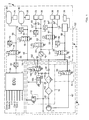
- Pressure medium lines are solid lines in the drawing, electrical lines are dashed lines.
- the drawing shows a compressed air treatment plant 2 with a compressed air supply part 4 and a consumer part 6.
- the compressed air supply part 4 comprises a compressor 7, a compressor control device 8 and an air dryer part 10.
- the consumer part 6 has a compressed air distribution line 14, a plurality of electrically directly or indirectly operable valves 16, 18, 20, 22, 24, preferably solenoid valves, with return spring and a plurality of supplied via the valves with compressed air consumer circuits 26,28, 30, 32,34, 36th , 38 on.
- a compressed air supply line 40 via a filter 42, an air dryer 44 and a check valve 46 to the manifold 14, from the leading to the solenoid valves lines 48, 50,52, 54,56 branch off.
- 24 lead compressed air lines 58, 60,62, 64, 66 to the consumer circuits.
- the line 62 branches into leading to the circles 30 and 32 lines 62 ', 62 ", wherein in the line 62" still a check valve 68 is arranged.
- a pressure limiter 70 is arranged in the supply line 52. Behind the pressure limiter 70, the line leading to the valve 22 22 branches off.
- the line 64 branches into lines 64 'and 64 "leading to the circles 34 and 36.
- Pressure sensors 72,74, 76,78, 80,82 monitor the pressure in the consumer circuits and in the distribution line 14 and give the respective pressure as a pressure signal to an electronic Control unit 84, which controls the valves directly.
- the consumer circuits 26, 28 can be, for example, service brake circuits
- the consumer circuit 30 can be a trailer brake circuit, with normally two lines leading to the trailer
- the consumer circuit 32 is a parking brake circuit with spring storage
- the consumer circuits 34 and 36 may be secondary consumption circuits, such as cab suspension, door control, etc., all that nothing has to do with the service brake circuits
- the load circuit 38 is a high pressure circuit for an air suspension system (shown as air bellows) is formed.
- An air suspension system usually requires high pressure because the air bags have a lot of volume and relatively high pressures.
- the service brake circuits 26, 28 have compressed air reservoirs 90, 92 in accordance with the guidelines 98/12 / EC.
- the compressor 7 is mechanically (pneumatically) controlled by the compressor controller 8.
- the compressor controller 8 comprises a valve 94 which can be switched by the electronic control unit 84 and which is vented in the de-energized basic state as illustrated. In this state, the compressor 7 is turned on and at least one consumer circuit is filled with compressed air. Upon reaching a set pressure threshold, the control unit 84 switches the valve 94, so that compressed air via a line 40 ', the compressed air compressor 7 turns off. If the valve 94 is de-energized for refilling due to air consumption, the valve 94 is switched back to the ground state shown in the drawing and the line 40 'is vented, so that the compressor 7 is turned on.
- the valve 94 may be a pneumatically switchable Valve be downstream, which is vented in the non-actuated basic state to relieve the compressor 7 in the actuated state.
- the air dryer section 10 comprises a valve 100 (with a small nominal diameter), whose inlet 102 is connected to the distribution line 14 and via whose output 104 a shut-off valve 106 is pneumatically connected, which is connected to the supply line 40 of the compressor 7 and serves to relieve the compressor ,
- valve 100 When the valve 100 is turned on, the compressor 7 no longer conveys into the consumer circuits, but via the valve 106 to the outside. At the same time dry air flows from the manifold 14 (from the containers 90,92 of the service brake circuits) via the valve 100 via a throttle 108 and a check valve 110 through the air dryer 44 for the regeneration of its desiccant and further through the filter 42 and the valve 106 to the outside ,
- the reference numeral 112 denotes a pressure relief valve.
- the valves 16 to 24 are controlled directly by the control unit 84, wherein the valves 16 to 22 of the load circuits 26 to 34 are open in the de-energized state, while the valve 24 of the high-pressure air-suspension circuit 38 is closed in the de-energized ground state.
- the pressure in the circuits is directly monitored by the pressure sensors 72 to 80.
- the air suspension circuit 38 is electronically controlled (also known as ECAS) by a controller 120 which is connected to the electronic control unit 84 via a data line 122.
- the control device 120 connected to the electronic control unit 84 via the data line 122 sends a compressed air request signal via the data line to the electronic control unit 84 when compressed air is required, for example as a result of leakage.
- the air suspension circuit 38 is then filled from the compressed air tanks 90, 92 of the brake circuits 26, 28 via the open valves 16, 18. If the pressure in the brake circuits drops below the prescribed value, this is communicated to the electronic control unit 84 by the brake circuit.
- the control unit 84 then closes the valve 24 and turns on the compressor 7 via the compressor controller 8.
- the compressor feeds into the brake circuits.
- the electronic control device 84 switches the valve 24 of the air-suspension circuit 38 back into the open position, so that the air-suspension circuit continues to be filled via the brake circuits or their compressed-air reservoirs 90, 92. This cyclic filling by the brake circuits is continued until the Soltik reached in the air suspension circuit 38. Then the valve 24 is closed again.
- the compressor usually promotes only in the brake circuits 26, 28. He can also - if necessary - promote the air suspension circuit, what then preferably the valves 16, 18 of the brake circuits are closed.
- the valves 20 and 22 of the secondary consumer circuits may remain open because the pressure in the associated consumer circuits 30-36 is limited by the pressure limiter 70.
- the Luftfedernik 38 has, as already mentioned above, usually a higher pressure level than the other circles; but he needs relatively little pressure and is therefore closed according to the invention without current. He also does not need within a very short time (msec or fractions of seconds) if necessary, his compressed air, so that one can take some dead time in the communication with the electronic control unit 84; the air spring circuit is therefore normally closed.
- the circuits 30 to 36 are supplied from the containers 90 and 92 of the service brake circuits 26 and 28, so that during normal driving their valves 16, 18, 20, and 22 are normally open.
- the electronic control device 84 switches the valve 16 or 18 upstream of the failed brake circuit into the blocking state and at the same time the lower pressure threshold of the normal pressure band of the intact brake circuit to a higher value, so that this brake circuit is filled to a higher pressure level.
- a higher braking energy is provided for the intact brake circuit, which increases the safety of the vehicle.
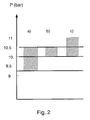
- Another increase The braking energy can be achieved if, in addition, the upper pressure threshold is also increased, cf. Fig.
- a) the normal pressure belt with a lower threshold of 9 bar and an upper threshold of 10.5 bar - without failure of a brake circuit b) the pressure band set according to the invention with, for example, 10 bar raised lower threshold and maintained upper threshold of 10.5 bar - in case of failure of a brake circuit and c) a pressure band set according to the invention with, for example, to 10 bar raised lower threshold and in addition, for example, to 11 bar raised upper threshold - in case of failure of a brake circuit.
Landscapes
- Engineering & Computer Science (AREA)
- Mechanical Engineering (AREA)
- Transportation (AREA)
- Valves And Accessory Devices For Braking Systems (AREA)
Applications Claiming Priority (1)
| Application Number | Priority Date | Filing Date | Title |
|---|---|---|---|
| DE102007050222.4A DE102007050222B4 (de) | 2007-10-20 | 2007-10-20 | Elektronische Luftaufbereitungsanlage |
Publications (2)
| Publication Number | Publication Date |
|---|---|
| EP2050596A1 true EP2050596A1 (fr) | 2009-04-22 |
| EP2050596B1 EP2050596B1 (fr) | 2015-11-18 |
Family
ID=40139812
Family Applications (1)
| Application Number | Title | Priority Date | Filing Date |
|---|---|---|---|
| EP08014327.4A Active EP2050596B1 (fr) | 2007-10-20 | 2008-08-12 | Dispositif électronique d'alimenation en air |
Country Status (2)
| Country | Link |
|---|---|
| EP (1) | EP2050596B1 (fr) |
| DE (1) | DE102007050222B4 (fr) |
Cited By (4)
| Publication number | Priority date | Publication date | Assignee | Title |
|---|---|---|---|---|
| EP2371644A3 (fr) * | 2009-12-22 | 2014-02-26 | Haldex Brake Products GmbH | Installation à air comprimé |
| CN108189636A (zh) * | 2018-01-12 | 2018-06-22 | 中国重汽集团济南动力有限公司 | 一种中重型汽车车桥二次提升装置 |
| EP4029746A1 (fr) * | 2021-01-19 | 2022-07-20 | KNORR-BREMSE Systeme für Nutzfahrzeuge GmbH | Soupape de protection commandée électroniquement |
| WO2023227267A1 (fr) * | 2022-05-23 | 2023-11-30 | Zf Cv Systems Global Gmbh | Dispositif de génération d'air comprimé et procédé pour faire fonctionner ce dispositif |
Families Citing this family (2)
| Publication number | Priority date | Publication date | Assignee | Title |
|---|---|---|---|---|
| DE102010024893B4 (de) | 2010-06-24 | 2021-11-04 | Zf Cv Systems Hannover Gmbh | Luftaufbereitungsanlage für ein Fahrzeug |
| DE102010024889B4 (de) | 2010-06-24 | 2014-12-11 | Wabco Gmbh | Luftversorgungseinrichtung für ein Fahrzeug mit pneumatischen Einrichtungen |
Citations (6)
| Publication number | Priority date | Publication date | Assignee | Title |
|---|---|---|---|---|
| US4071284A (en) * | 1974-08-07 | 1978-01-31 | Messier-Hispano | Method and apparatus for effecting double-acting braking |
| DE19515895A1 (de) | 1995-04-29 | 1996-10-31 | Bosch Gmbh Robert | Druckluft-Versorgungseinrichtung für Fahrzeug-Druckluftanlagen sowie Verfahren zum Steuern der Druckluft-Versorgungseinrichtung |
| WO1998047751A1 (fr) | 1997-04-23 | 1998-10-29 | Wabco Automotive U.K. Limited | Systeme de freinage de vehicule et son procede de fonctionnement |
| DE10004091C2 (de) | 2000-01-31 | 2002-11-14 | Knorr Bremse Systeme | Druckluftversorgungseinrichtung für Fahrzeug-Druckluftanlagen |
| EP1361132A1 (fr) * | 2002-05-10 | 2003-11-12 | Haldex Brake Products GmbH | Dispositif de distribution d'air comprimé pour un système pneumatique pour automobile |
| WO2005014353A1 (fr) * | 2003-07-28 | 2005-02-17 | Wabco Gmbh & Co. Ohg | Procede et dispositif pour detecter un defaut ou une defaillance d'un circuit consommateur d'air comprime dans un systeme electronique a air comprime pour des vehicules |
Family Cites Families (2)
| Publication number | Priority date | Publication date | Assignee | Title |
|---|---|---|---|---|
| WO2005014360A1 (fr) | 2003-07-28 | 2005-02-17 | Wabco Gmbh & Co. Ohg | Procede et dispositif pour detecter une defaillance d'un circuit consommateur d'air comprime dans un systeme electronique a air comprime pour des vehicules |
| DE10357765A1 (de) | 2003-07-28 | 2005-03-10 | Wabco Gmbh & Co Ohg | Verfahren zum Wiederbefüllen von Bremskreisen nach einem starken Druckluftverbrauch und Vorrichtung zur Durchführung des Verfahrens |
-
2007
- 2007-10-20 DE DE102007050222.4A patent/DE102007050222B4/de not_active Expired - Fee Related
-
2008
- 2008-08-12 EP EP08014327.4A patent/EP2050596B1/fr active Active
Patent Citations (6)
| Publication number | Priority date | Publication date | Assignee | Title |
|---|---|---|---|---|
| US4071284A (en) * | 1974-08-07 | 1978-01-31 | Messier-Hispano | Method and apparatus for effecting double-acting braking |
| DE19515895A1 (de) | 1995-04-29 | 1996-10-31 | Bosch Gmbh Robert | Druckluft-Versorgungseinrichtung für Fahrzeug-Druckluftanlagen sowie Verfahren zum Steuern der Druckluft-Versorgungseinrichtung |
| WO1998047751A1 (fr) | 1997-04-23 | 1998-10-29 | Wabco Automotive U.K. Limited | Systeme de freinage de vehicule et son procede de fonctionnement |
| DE10004091C2 (de) | 2000-01-31 | 2002-11-14 | Knorr Bremse Systeme | Druckluftversorgungseinrichtung für Fahrzeug-Druckluftanlagen |
| EP1361132A1 (fr) * | 2002-05-10 | 2003-11-12 | Haldex Brake Products GmbH | Dispositif de distribution d'air comprimé pour un système pneumatique pour automobile |
| WO2005014353A1 (fr) * | 2003-07-28 | 2005-02-17 | Wabco Gmbh & Co. Ohg | Procede et dispositif pour detecter un defaut ou une defaillance d'un circuit consommateur d'air comprime dans un systeme electronique a air comprime pour des vehicules |
Cited By (5)
| Publication number | Priority date | Publication date | Assignee | Title |
|---|---|---|---|---|
| EP2371644A3 (fr) * | 2009-12-22 | 2014-02-26 | Haldex Brake Products GmbH | Installation à air comprimé |
| CN108189636A (zh) * | 2018-01-12 | 2018-06-22 | 中国重汽集团济南动力有限公司 | 一种中重型汽车车桥二次提升装置 |
| CN108189636B (zh) * | 2018-01-12 | 2021-01-22 | 中国重汽集团济南动力有限公司 | 一种中重型汽车车桥二次提升装置 |
| EP4029746A1 (fr) * | 2021-01-19 | 2022-07-20 | KNORR-BREMSE Systeme für Nutzfahrzeuge GmbH | Soupape de protection commandée électroniquement |
| WO2023227267A1 (fr) * | 2022-05-23 | 2023-11-30 | Zf Cv Systems Global Gmbh | Dispositif de génération d'air comprimé et procédé pour faire fonctionner ce dispositif |
Also Published As
| Publication number | Publication date |
|---|---|
| DE102007050222B4 (de) | 2022-02-10 |
| DE102007050222A1 (de) | 2009-04-23 |
| EP2050596B1 (fr) | 2015-11-18 |
Similar Documents
| Publication | Publication Date | Title |
|---|---|---|
| EP1651492B1 (fr) | Dispositif electronique a air comprime | |
| EP3145769B1 (fr) | Moyen de commande de freinage électropneumatique avec purge automatique du frein à accumulation en cas de panne de courant | |
| EP2445736B1 (fr) | Systeme d'alimentation en air comprime pour un circuit consommateur d'air comprime, notamment pour un systeme de suspension pneumatique | |
| DE102005057004B3 (de) | Druckluftaufbereitungseinrichtung und Verfahren zum Betreiben einer Druckluftaufbereitungseinrichtung | |
| EP2615003B2 (fr) | Module de frein de stationnement pour une installation de freinage entraînée par pression d'un véhicule adapté au couplage d'une remorque, installation de freinage et véhicule avec le module de frein de stationnement et procédé pour celui-ci | |
| DE10357762A1 (de) | Elektronische Druckluftanlage | |
| DE102006048071A1 (de) | Druckluftversorgungsanlage und Verfahren zur Parameter-Ermittlung der Anlage | |
| EP2836406B1 (fr) | Système d'air comprimé pour l'approvisionnement d'air d'un camion | |
| EP2050596B1 (fr) | Dispositif électronique d'alimenation en air | |
| WO2008113549A1 (fr) | Dispositif d'alimentation en air comprimé pour un véhicule utilitaire et procédé pour la commande d'un dispositif d'alimentation en air comprimé | |
| EP1651489B1 (fr) | Systeme electronique a air comprime | |
| EP1651491B1 (fr) | Dispositif de réalimentation de circuits de freinage après une consommation importante d'air comprimé et dispositif pour mettre en oeuvre ce procédé | |
| EP1508488B2 (fr) | Installation de production d'air comprimé pour véhicule et méthode pour le faire fonctionner | |
| DE102008021818B4 (de) | Verfahren zum Steuern einer Niveauregelanlage sowie Niveauregelanlage | |
| EP3112231B1 (fr) | Module de frein de stationnement, installation de freinage et vehicule ainsi equipe et procede de fonctionnement d'un dispositif de frein de stationnement avec un tel module | |
| EP1651493A1 (fr) | Procede et dispositif pour detecter une defaillance d'un circuit consommateur d'air comprime dans un systeme electronique a air comprime pour des vehicules | |
| EP2177381B1 (fr) | Ensemble de clapets pour un système de suspension pneumatique | |
| EP3411275A1 (fr) | Système de freinage pour véhicule utilitaire | |
| DE102018217405A1 (de) | Druckluftaufbereitungssystem | |
| EP2226205A1 (fr) | Procédé pour le réglage de pression de pneux et système de réglage de la pression de pneux | |
| EP2789512A1 (fr) | Dispositif de préparation d'air comprimé pour un véhicule utilitaire | |
| EP1800984B1 (fr) | Procédé de réalimentation de circuits de freinage après une consommation importante d'air comprimé | |
| EP2371644A2 (fr) | Installation à air comprimé |
Legal Events
| Date | Code | Title | Description |
|---|---|---|---|
| PUAI | Public reference made under article 153(3) epc to a published international application that has entered the european phase |
Free format text: ORIGINAL CODE: 0009012 |
|
| AK | Designated contracting states |
Kind code of ref document: A1 Designated state(s): AT BE BG CH CY CZ DE DK EE ES FI FR GB GR HR HU IE IS IT LI LT LU LV MC MT NL NO PL PT RO SE SI SK TR |
|
| AX | Request for extension of the european patent |
Extension state: AL BA MK RS |
|
| 17P | Request for examination filed |
Effective date: 20091022 |
|
| AKX | Designation fees paid |
Designated state(s): AT BE BG CH CY CZ DE DK EE ES FI FR GB GR HR HU IE IS IT LI LT LU LV MC MT NL NO PL PT RO SE SI SK TR |
|
| GRAP | Despatch of communication of intention to grant a patent |
Free format text: ORIGINAL CODE: EPIDOSNIGR1 |
|
| INTG | Intention to grant announced |
Effective date: 20140109 |
|
| 17Q | First examination report despatched |
Effective date: 20140226 |
|
| GRAP | Despatch of communication of intention to grant a patent |
Free format text: ORIGINAL CODE: EPIDOSNIGR1 |
|
| INTG | Intention to grant announced |
Effective date: 20150622 |
|
| GRAP | Despatch of communication of intention to grant a patent |
Free format text: ORIGINAL CODE: EPIDOSNIGR1 |
|
| INTG | Intention to grant announced |
Effective date: 20150807 |
|
| GRAS | Grant fee paid |
Free format text: ORIGINAL CODE: EPIDOSNIGR3 |
|
| GRAA | (expected) grant |
Free format text: ORIGINAL CODE: 0009210 |
|
| AK | Designated contracting states |
Kind code of ref document: B1 Designated state(s): AT BE BG CH CY CZ DE DK EE ES FI FR GB GR HR HU IE IS IT LI LT LU LV MC MT NL NO PL PT RO SE SI SK TR |
|
| REG | Reference to a national code |
Ref country code: GB Ref legal event code: FG4D Free format text: NOT ENGLISH |
|
| REG | Reference to a national code |
Ref country code: CH Ref legal event code: EP |
|
| REG | Reference to a national code |
Ref country code: AT Ref legal event code: REF Ref document number: 761352 Country of ref document: AT Kind code of ref document: T Effective date: 20151215 |
|
| REG | Reference to a national code |
Ref country code: IE Ref legal event code: FG4D Free format text: LANGUAGE OF EP DOCUMENT: GERMAN |
|
| REG | Reference to a national code |
Ref country code: DE Ref legal event code: R096 Ref document number: 502008013584 Country of ref document: DE |
|
| REG | Reference to a national code |
Ref country code: SE Ref legal event code: TRGR |
|
| REG | Reference to a national code |
Ref country code: NL Ref legal event code: MP Effective date: 20160218 |
|
| REG | Reference to a national code |
Ref country code: LT Ref legal event code: MG4D |
|
| PG25 | Lapsed in a contracting state [announced via postgrant information from national office to epo] |
Ref country code: HR Free format text: LAPSE BECAUSE OF FAILURE TO SUBMIT A TRANSLATION OF THE DESCRIPTION OR TO PAY THE FEE WITHIN THE PRESCRIBED TIME-LIMIT Effective date: 20151118 Ref country code: ES Free format text: LAPSE BECAUSE OF FAILURE TO SUBMIT A TRANSLATION OF THE DESCRIPTION OR TO PAY THE FEE WITHIN THE PRESCRIBED TIME-LIMIT Effective date: 20151118 Ref country code: IT Free format text: LAPSE BECAUSE OF FAILURE TO SUBMIT A TRANSLATION OF THE DESCRIPTION OR TO PAY THE FEE WITHIN THE PRESCRIBED TIME-LIMIT Effective date: 20151118 Ref country code: NO Free format text: LAPSE BECAUSE OF FAILURE TO SUBMIT A TRANSLATION OF THE DESCRIPTION OR TO PAY THE FEE WITHIN THE PRESCRIBED TIME-LIMIT Effective date: 20160218 Ref country code: IS Free format text: LAPSE BECAUSE OF FAILURE TO SUBMIT A TRANSLATION OF THE DESCRIPTION OR TO PAY THE FEE WITHIN THE PRESCRIBED TIME-LIMIT Effective date: 20160318 Ref country code: NL Free format text: LAPSE BECAUSE OF FAILURE TO SUBMIT A TRANSLATION OF THE DESCRIPTION OR TO PAY THE FEE WITHIN THE PRESCRIBED TIME-LIMIT Effective date: 20151118 Ref country code: LT Free format text: LAPSE BECAUSE OF FAILURE TO SUBMIT A TRANSLATION OF THE DESCRIPTION OR TO PAY THE FEE WITHIN THE PRESCRIBED TIME-LIMIT Effective date: 20151118 |
|
| PG25 | Lapsed in a contracting state [announced via postgrant information from national office to epo] |
Ref country code: PT Free format text: LAPSE BECAUSE OF FAILURE TO SUBMIT A TRANSLATION OF THE DESCRIPTION OR TO PAY THE FEE WITHIN THE PRESCRIBED TIME-LIMIT Effective date: 20160318 Ref country code: GR Free format text: LAPSE BECAUSE OF FAILURE TO SUBMIT A TRANSLATION OF THE DESCRIPTION OR TO PAY THE FEE WITHIN THE PRESCRIBED TIME-LIMIT Effective date: 20160219 Ref country code: FI Free format text: LAPSE BECAUSE OF FAILURE TO SUBMIT A TRANSLATION OF THE DESCRIPTION OR TO PAY THE FEE WITHIN THE PRESCRIBED TIME-LIMIT Effective date: 20151118 Ref country code: PL Free format text: LAPSE BECAUSE OF FAILURE TO SUBMIT A TRANSLATION OF THE DESCRIPTION OR TO PAY THE FEE WITHIN THE PRESCRIBED TIME-LIMIT Effective date: 20151118 Ref country code: LV Free format text: LAPSE BECAUSE OF FAILURE TO SUBMIT A TRANSLATION OF THE DESCRIPTION OR TO PAY THE FEE WITHIN THE PRESCRIBED TIME-LIMIT Effective date: 20151118 |
|
| PG25 | Lapsed in a contracting state [announced via postgrant information from national office to epo] |
Ref country code: CZ Free format text: LAPSE BECAUSE OF FAILURE TO SUBMIT A TRANSLATION OF THE DESCRIPTION OR TO PAY THE FEE WITHIN THE PRESCRIBED TIME-LIMIT Effective date: 20151118 |
|
| REG | Reference to a national code |
Ref country code: DE Ref legal event code: R097 Ref document number: 502008013584 Country of ref document: DE |
|
| REG | Reference to a national code |
Ref country code: FR Ref legal event code: PLFP Year of fee payment: 9 |
|
| PG25 | Lapsed in a contracting state [announced via postgrant information from national office to epo] |
Ref country code: RO Free format text: LAPSE BECAUSE OF FAILURE TO SUBMIT A TRANSLATION OF THE DESCRIPTION OR TO PAY THE FEE WITHIN THE PRESCRIBED TIME-LIMIT Effective date: 20151118 Ref country code: EE Free format text: LAPSE BECAUSE OF FAILURE TO SUBMIT A TRANSLATION OF THE DESCRIPTION OR TO PAY THE FEE WITHIN THE PRESCRIBED TIME-LIMIT Effective date: 20151118 Ref country code: DK Free format text: LAPSE BECAUSE OF FAILURE TO SUBMIT A TRANSLATION OF THE DESCRIPTION OR TO PAY THE FEE WITHIN THE PRESCRIBED TIME-LIMIT Effective date: 20151118 Ref country code: SK Free format text: LAPSE BECAUSE OF FAILURE TO SUBMIT A TRANSLATION OF THE DESCRIPTION OR TO PAY THE FEE WITHIN THE PRESCRIBED TIME-LIMIT Effective date: 20151118 |
|
| PLBE | No opposition filed within time limit |
Free format text: ORIGINAL CODE: 0009261 |
|
| STAA | Information on the status of an ep patent application or granted ep patent |
Free format text: STATUS: NO OPPOSITION FILED WITHIN TIME LIMIT |
|
| 26N | No opposition filed |
Effective date: 20160819 |
|
| PG25 | Lapsed in a contracting state [announced via postgrant information from national office to epo] |
Ref country code: SI Free format text: LAPSE BECAUSE OF FAILURE TO SUBMIT A TRANSLATION OF THE DESCRIPTION OR TO PAY THE FEE WITHIN THE PRESCRIBED TIME-LIMIT Effective date: 20151118 |
|
| PG25 | Lapsed in a contracting state [announced via postgrant information from national office to epo] |
Ref country code: BE Free format text: LAPSE BECAUSE OF NON-PAYMENT OF DUE FEES Effective date: 20160831 |
|
| PG25 | Lapsed in a contracting state [announced via postgrant information from national office to epo] |
Ref country code: MC Free format text: LAPSE BECAUSE OF FAILURE TO SUBMIT A TRANSLATION OF THE DESCRIPTION OR TO PAY THE FEE WITHIN THE PRESCRIBED TIME-LIMIT Effective date: 20151118 |
|
| REG | Reference to a national code |
Ref country code: CH Ref legal event code: PL |
|
| PG25 | Lapsed in a contracting state [announced via postgrant information from national office to epo] |
Ref country code: CH Free format text: LAPSE BECAUSE OF NON-PAYMENT OF DUE FEES Effective date: 20160831 Ref country code: LI Free format text: LAPSE BECAUSE OF NON-PAYMENT OF DUE FEES Effective date: 20160831 |
|
| REG | Reference to a national code |
Ref country code: IE Ref legal event code: MM4A |
|
| PG25 | Lapsed in a contracting state [announced via postgrant information from national office to epo] |
Ref country code: IE Free format text: LAPSE BECAUSE OF NON-PAYMENT OF DUE FEES Effective date: 20160812 |
|
| REG | Reference to a national code |
Ref country code: FR Ref legal event code: PLFP Year of fee payment: 10 |
|
| PG25 | Lapsed in a contracting state [announced via postgrant information from national office to epo] |
Ref country code: LU Free format text: LAPSE BECAUSE OF NON-PAYMENT OF DUE FEES Effective date: 20160812 |
|
| REG | Reference to a national code |
Ref country code: AT Ref legal event code: MM01 Ref document number: 761352 Country of ref document: AT Kind code of ref document: T Effective date: 20160812 |
|
| PG25 | Lapsed in a contracting state [announced via postgrant information from national office to epo] |
Ref country code: AT Free format text: LAPSE BECAUSE OF NON-PAYMENT OF DUE FEES Effective date: 20160812 |
|
| REG | Reference to a national code |
Ref country code: DE Ref legal event code: R081 Ref document number: 502008013584 Country of ref document: DE Owner name: WABCO EUROPE BVBA, BE Free format text: FORMER OWNER: WABCO GMBH, 30453 HANNOVER, DE |
|
| PG25 | Lapsed in a contracting state [announced via postgrant information from national office to epo] |
Ref country code: HU Free format text: LAPSE BECAUSE OF FAILURE TO SUBMIT A TRANSLATION OF THE DESCRIPTION OR TO PAY THE FEE WITHIN THE PRESCRIBED TIME-LIMIT; INVALID AB INITIO Effective date: 20080812 Ref country code: CY Free format text: LAPSE BECAUSE OF FAILURE TO SUBMIT A TRANSLATION OF THE DESCRIPTION OR TO PAY THE FEE WITHIN THE PRESCRIBED TIME-LIMIT Effective date: 20151118 |
|
| PG25 | Lapsed in a contracting state [announced via postgrant information from national office to epo] |
Ref country code: TR Free format text: LAPSE BECAUSE OF FAILURE TO SUBMIT A TRANSLATION OF THE DESCRIPTION OR TO PAY THE FEE WITHIN THE PRESCRIBED TIME-LIMIT Effective date: 20151118 Ref country code: MT Free format text: LAPSE BECAUSE OF FAILURE TO SUBMIT A TRANSLATION OF THE DESCRIPTION OR TO PAY THE FEE WITHIN THE PRESCRIBED TIME-LIMIT Effective date: 20151118 |
|
| PG25 | Lapsed in a contracting state [announced via postgrant information from national office to epo] |
Ref country code: BG Free format text: LAPSE BECAUSE OF FAILURE TO SUBMIT A TRANSLATION OF THE DESCRIPTION OR TO PAY THE FEE WITHIN THE PRESCRIBED TIME-LIMIT Effective date: 20151118 |
|
| REG | Reference to a national code |
Ref country code: FR Ref legal event code: PLFP Year of fee payment: 11 |
|
| PGFP | Annual fee paid to national office [announced via postgrant information from national office to epo] |
Ref country code: FR Payment date: 20210823 Year of fee payment: 14 |
|
| PGFP | Annual fee paid to national office [announced via postgrant information from national office to epo] |
Ref country code: SE Payment date: 20210823 Year of fee payment: 14 Ref country code: GB Payment date: 20210824 Year of fee payment: 14 |
|
| REG | Reference to a national code |
Ref country code: SE Ref legal event code: EUG |
|
| GBPC | Gb: european patent ceased through non-payment of renewal fee |
Effective date: 20220812 |
|
| PG25 | Lapsed in a contracting state [announced via postgrant information from national office to epo] |
Ref country code: SE Free format text: LAPSE BECAUSE OF NON-PAYMENT OF DUE FEES Effective date: 20220813 |
|
| REG | Reference to a national code |
Ref country code: DE Ref legal event code: R081 Ref document number: 502008013584 Country of ref document: DE Owner name: ZF CV SYSTEMS EUROPE BV, BE Free format text: FORMER OWNER: WABCO EUROPE BVBA, BRUESSEL, BE |
|
| P01 | Opt-out of the competence of the unified patent court (upc) registered |
Effective date: 20230528 |
|
| PG25 | Lapsed in a contracting state [announced via postgrant information from national office to epo] |
Ref country code: FR Free format text: LAPSE BECAUSE OF NON-PAYMENT OF DUE FEES Effective date: 20220831 |
|
| PG25 | Lapsed in a contracting state [announced via postgrant information from national office to epo] |
Ref country code: GB Free format text: LAPSE BECAUSE OF NON-PAYMENT OF DUE FEES Effective date: 20220812 |
|
| PGFP | Annual fee paid to national office [announced via postgrant information from national office to epo] |
Ref country code: DE Payment date: 20250618 Year of fee payment: 18 |