EP2050669A2 - Système, procédé et appareil pour structures de bord d'attaque et leur fabrication directe - Google Patents
Système, procédé et appareil pour structures de bord d'attaque et leur fabrication directe Download PDFInfo
- Publication number
- EP2050669A2 EP2050669A2 EP08166496A EP08166496A EP2050669A2 EP 2050669 A2 EP2050669 A2 EP 2050669A2 EP 08166496 A EP08166496 A EP 08166496A EP 08166496 A EP08166496 A EP 08166496A EP 2050669 A2 EP2050669 A2 EP 2050669A2
- Authority
- EP
- European Patent Office
- Prior art keywords
- leading edge
- edge structure
- wing
- aircraft
- wing box
- Prior art date
- Legal status (The legal status is an assumption and is not a legal conclusion. Google has not performed a legal analysis and makes no representation as to the accuracy of the status listed.)
- Withdrawn
Links
- 238000000034 method Methods 0.000 title claims abstract description 32
- 238000004519 manufacturing process Methods 0.000 title abstract description 10
- 239000000463 material Substances 0.000 claims abstract description 27
- 239000000919 ceramic Substances 0.000 claims abstract description 7
- 239000003870 refractory metal Substances 0.000 claims abstract description 7
- 238000001816 cooling Methods 0.000 claims description 14
- 239000012530 fluid Substances 0.000 claims description 7
- 229910000753 refractory alloy Inorganic materials 0.000 claims description 4
- 238000000151 deposition Methods 0.000 claims description 3
- 239000003351 stiffener Substances 0.000 claims description 2
- 229910045601 alloy Inorganic materials 0.000 abstract description 5
- 239000000956 alloy Substances 0.000 abstract description 5
- 238000005266 casting Methods 0.000 abstract description 2
- 238000005516 engineering process Methods 0.000 abstract description 2
- 238000003754 machining Methods 0.000 description 3
- 238000013459 approach Methods 0.000 description 2
- 238000005452 bending Methods 0.000 description 2
- -1 etc.) Inorganic materials 0.000 description 2
- 229910052751 metal Inorganic materials 0.000 description 2
- 239000002184 metal Substances 0.000 description 2
- 229910052702 rhenium Inorganic materials 0.000 description 2
- 230000009286 beneficial effect Effects 0.000 description 1
- 238000010586 diagram Methods 0.000 description 1
- 229910001026 inconel Inorganic materials 0.000 description 1
- 230000010354 integration Effects 0.000 description 1
Images


Classifications
-
- B—PERFORMING OPERATIONS; TRANSPORTING
- B64—AIRCRAFT; AVIATION; COSMONAUTICS
- B64C—AEROPLANES; HELICOPTERS
- B64C3/00—Wings
- B64C3/28—Leading or trailing edges attached to primary structures, e.g. forming fixed slots
-
- B—PERFORMING OPERATIONS; TRANSPORTING
- B64—AIRCRAFT; AVIATION; COSMONAUTICS
- B64F—GROUND OR AIRCRAFT-CARRIER-DECK INSTALLATIONS SPECIALLY ADAPTED FOR USE IN CONNECTION WITH AIRCRAFT; DESIGNING, MANUFACTURING, ASSEMBLING, CLEANING, MAINTAINING OR REPAIRING AIRCRAFT, NOT OTHERWISE PROVIDED FOR; HANDLING, TRANSPORTING, TESTING OR INSPECTING AIRCRAFT COMPONENTS, NOT OTHERWISE PROVIDED FOR
- B64F5/00—Designing, manufacturing, assembling, cleaning, maintaining or repairing aircraft, not otherwise provided for; Handling, transporting, testing or inspecting aircraft components, not otherwise provided for
Definitions
- the present invention relates in general to high speed aircraft and, in particular, to an improved system, method, and apparatus for direct manufacturing of leading edge structures for high speed aircraft.
- Tight-radiused leading edge structures on high speed air vehicles can experience very high operating temperatures while in service.
- Conventional manufacturing approaches such as machining from billets of material, sheet metal forming, etc. have been used to fabricate such structures. These methods are expensive and slow, and they also are limited as to the types of materials that can be machined and/or bent into appropriate shapes. Depending on which existing method is used, there are additional geometric limitations to the types of leading edges that can be produced. Thus, an improved system, method, and apparatus for fabricating leading edge structures would be desirable. The ability to fabricate such structures out of high temperature materials in a quick and cost-effective manner would be even more beneficial.
- Embodiments of a system, method, and apparatus for leading edge structures for high performance aircraft and for the direct manufacture thereof are disclosed.
- the invention leverages direct manufacturing technology to deposit leading edge structures directly from a digital model. Instead of sheet metal bending or bulk machining approaches, this method deposits material into a near-net shape product, saving considerable time and cost in fabricating these structures as well as allowing a wider range of materials to be utilized.
- the invention permits a wider variety of materials to be employed for very demanding applications. Some alloys that are capable of the highest temperature usage are not available in billet form for machining, or in sheet form for bending.
- the deposition method of the invention allows for the use of casting materials that otherwise could not be considered.
- Turbine blade alloys e.g., Inconel 100
- Refractory metals e.g., W, Ta, Re, etc.
- alloys IN625, UDIMET 720, W-Re
- high temperature ceramics also may be used for such purposes. These materials may be used for the entire leading edge structure, or just for the tip of the leading edge structure.
- Such tip designs may be configured to be replaceable or repaired as needed with, e.g., tolerance-fit, keyway-jointed, or other assembly techniques.
- cooling channels may be incorporated into the structure.
- temperature use of a given material may be expanded in a manner similar to the way turbine blades are made with active cooling channels to allow for higher temperature use.
- stiffening elements may be incorporated into the structure to permit weight to be minimized by tailoring the structure to given design loads.
- the invention allows for a variable geometry along the span of the leading edge. Again, this would allow structural and aerodynamic tailoring of a leading edge based on thermal, aerodynamic or structural requirements.
- self-locating features may be built into the structure to allow for a low tooling and/or tool-free assembly. For example, a tongue-and-groove configuration would allow sections to be assembled and then permanently joined (e.g., welded, bonded, etc.). Self-locating features also may be included to readily allow for integration with the leading edge spar.
- FIG. 1 is an isometric view of one embodiment of an aircraft constructed in accordance with the invention
- FIG. 2 is an enlarged isometric view of a portion of one embodiment of a leading edge structure constructed in accordance with the invention
- FIG. 3 is an isometric view of another embodiment of a leading edge structure constructed in accordance with the invention.
- FIG. 4 is an enlarged isometric view of another portion of the leading edge of FIG. 3 and is constructed in accordance with the invention.
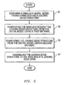
- FIG. 5 is a high level flow diagram of one embodiment of a method in accordance with the invention.
- FIGS. 1 - 5 embodiments of a system, method and apparatus for directly manufacturing tightly-radiused structures from digital models are shown.
- the invention is well suited for fabricating leading edge structures I 1 ( FIG. 1 ) on wings 13 and other features 17 of a high speed aircraft 15 for better performance at higher operational temperatures.
- the aircraft wing 13 may comprise a wing box 21 having a fixed leading edge assembly 23 that may be joined to the wing box 21 at the leading edge spar 29.
- the leading edge assembly 23 may comprise an aft section 25 and a replaceable tip 27.
- the replaceable tip 27 may be mated to the aft section of the leading edge assembly with a mechanical assembly technique such as a tolerance fit, keyway joint or other methods.
- the leading edge assembly 23 may be fabricated with a variable geometry extending along the direction 22 defined by the leading edge such that it is non-symmetrical or non-uniform along the span.
- the leading edge is a one-piece structure 33.
- the leading edge structure 33 may be configured to be detachably removable from the wing box 31 at the leading edge spar 35, and is therefore repairable or replaceable.
- the leading edge 33 may be mated to the wing box 31 with a mechanical assembly technique such as fastening or other methods.
- the leading edge structure 23, 33 may be fabricated apart from the wing and then attached. This manufacturing technique permits the leading edge to be formed from refractory metals (e.g., W, Ta, Re, etc.), alloys (IN625, UDIMET 720, W-Re), high temperature ceramics, or other non-traditional materials.
- the leading edge structure 23, 33 may be formed from a first material, and other portions of the wing box 21, 31 may be formed from a second material.
- the leading edge structure 33 comprises integrally formed stiffeners 39 that also may be formed from the first material.
- the invention further comprises one or more cooling channels 41 that extend through the leading edge structure 23, 33 along the direction defined by the leading edge span.
- the cooling channels 41 comprise at least one fluid conduit (e.g., three shown) for communicating a fluid through the leading edge (such as tip 27 in FIG. 2 ) for reducing a temperature thereof.
- the invention also comprises a method of forming a wing of an aircraft.
- one embodiment of the method comprises designing a wing as a digital model having a wing box and a leading edge structure (step 51); fabricating the wing box without the leading edge structure from the digital model using a first material (step 53); fabricating the leading edge structure from the digital model using a second material (step 55); and assembling the leading edge structure to the wing box at a leading edge spar (step 57); before ending as indicated.
- the method also may comprise selecting the second material from the group consisting of refractory metals, refractory alloys, and ceramics.
- the method may further comprise fabricating a replaceable tip separately from the leading edge structure, and then mechanically assembling the replaceable tip to the leading edge structure.
- the method may further comprise: forming at least one cooling channel in the leading edge structure for circulating a fluid therethrough for cooling the leading edge structure; and/or forming stiffening elements in the leading edge structure; and/or forming the leading edge structure with a variable geometry along a span of the wing.
Landscapes
- Engineering & Computer Science (AREA)
- Aviation & Aerospace Engineering (AREA)
- Mechanical Engineering (AREA)
- Manufacturing & Machinery (AREA)
- Transportation (AREA)
- Turbine Rotor Nozzle Sealing (AREA)
- Powder Metallurgy (AREA)
Applications Claiming Priority (1)
| Application Number | Priority Date | Filing Date | Title |
|---|---|---|---|
| US11/873,439 US7871041B2 (en) | 2007-10-17 | 2007-10-17 | System, method, and apparatus for leading edge structures and direct manufacturing thereof |
Publications (2)
| Publication Number | Publication Date |
|---|---|
| EP2050669A2 true EP2050669A2 (fr) | 2009-04-22 |
| EP2050669A3 EP2050669A3 (fr) | 2015-09-09 |
Family
ID=40225305
Family Applications (1)
| Application Number | Title | Priority Date | Filing Date |
|---|---|---|---|
| EP08166496.3A Withdrawn EP2050669A3 (fr) | 2007-10-17 | 2008-10-13 | Système, procédé et appareil pour structures de bord d'attaque et leur fabrication directe |
Country Status (2)
| Country | Link |
|---|---|
| US (1) | US7871041B2 (fr) |
| EP (1) | EP2050669A3 (fr) |
Cited By (2)
| Publication number | Priority date | Publication date | Assignee | Title |
|---|---|---|---|---|
| WO2013078649A1 (fr) * | 2011-11-30 | 2013-06-06 | Airbus S.A.S. | Composant présentant une structure en caisson pour plan porteur d'avion |
| CN109572996A (zh) * | 2018-12-04 | 2019-04-05 | 中国航空工业集团公司西安飞机设计研究所 | 一种考虑温度变化的尾翼抗鸟撞附加蒙皮前缘结构 |
Families Citing this family (12)
| Publication number | Priority date | Publication date | Assignee | Title |
|---|---|---|---|---|
| GB0803689D0 (en) * | 2008-02-29 | 2008-04-09 | Airbus Uk Ltd | Trailing edge aircraft structure with overhaning cover |
| US9012824B2 (en) * | 2011-03-16 | 2015-04-21 | Raytheon Company | Low-heat-transfer interface between metal parts |
| ES2421410B1 (es) * | 2012-02-29 | 2014-10-28 | Airbus Operations, S.L. | Borde de salida de una superficie aerodinamica de una aeronave |
| BR112015011344A2 (pt) * | 2012-11-20 | 2017-07-11 | Saab Ab | borda de ataque de uma fuselagem |
| CN105000166A (zh) * | 2015-04-29 | 2015-10-28 | 中国航空工业集团公司北京航空材料研究院 | 一种用于高马赫飞行器的隔热结构 |
| JP6782533B2 (ja) * | 2015-08-26 | 2020-11-11 | 三菱航空機株式会社 | 航空機の前縁構造体、航空機の翼及び航空機 |
| CN107434031A (zh) * | 2016-05-25 | 2017-12-05 | 空中客车简化股份公司 | 飞行器翼体的结构部件和包括该结构部件的飞行器 |
| GB2552343A (en) * | 2016-07-19 | 2018-01-24 | Airbus Operations Ltd | Method of manufacturing a multi-alloy aerospace component |
| US10647406B2 (en) * | 2017-06-01 | 2020-05-12 | The Boeing Company | Closed-angle composite airfoil spar and method of fabricating the same |
| GB2573286B (en) * | 2018-04-27 | 2020-10-14 | Airbus Operations Ltd | Winglet |
| KR102184614B1 (ko) * | 2019-07-26 | 2020-11-30 | 국방과학연구소 | 이종 재료를 이용한 날개 및 이를 포함하는 발사체 |
| CN114771802A (zh) * | 2021-01-22 | 2022-07-22 | 波音公司 | 空气动力学结构以及形成空气动力学结构的方法 |
Family Cites Families (15)
| Publication number | Priority date | Publication date | Assignee | Title |
|---|---|---|---|---|
| US3176775A (en) * | 1963-05-28 | 1965-04-06 | Clemens Ronald | Structures of aerofoil shape |
| US4232093A (en) * | 1973-10-29 | 1980-11-04 | Summa Corporation | High temperature skin construction |
| US4667906A (en) * | 1985-04-02 | 1987-05-26 | Grumman Aerospace Corporation | Replaceable tip for aircraft leading edge |
| US4671348A (en) * | 1985-05-21 | 1987-06-09 | Mcdonnell Douglas Corporation | Transverse flow edge heat pipe |
| US4786015A (en) * | 1986-12-31 | 1988-11-22 | Sundstrand Corporation | Structural cooling unit |
| JP3647612B2 (ja) * | 1997-07-24 | 2005-05-18 | 富士重工業株式会社 | 航空機の前縁構造及びその製造方法 |
| JP2000006893A (ja) * | 1998-06-23 | 2000-01-11 | Fuji Heavy Ind Ltd | 複合材翼構造 |
| JP2000043796A (ja) * | 1998-07-30 | 2000-02-15 | Japan Aircraft Development Corp | 複合材の翼形構造およびその成形方法 |
| US6455132B1 (en) * | 1999-02-04 | 2002-09-24 | Kodak Polychrome Graphics Llc | Lithographic printing printable media and process for the production thereof |
| JP4316059B2 (ja) * | 1999-08-06 | 2009-08-19 | 富士重工業株式会社 | 複合材翼の製造方法 |
| US6367740B1 (en) * | 2000-05-16 | 2002-04-09 | The Boeing Company | Air foil having a hybrid leading edge construction |
| US6746755B2 (en) * | 2001-09-24 | 2004-06-08 | Siemens Westinghouse Power Corporation | Ceramic matrix composite structure having integral cooling passages and method of manufacture |
| US6779757B2 (en) * | 2002-06-28 | 2004-08-24 | Lockheed Martin Corporation | Preforms for acute structural edges |
| US7066717B2 (en) * | 2004-04-22 | 2006-06-27 | Siemens Power Generation, Inc. | Ceramic matrix composite airfoil trailing edge arrangement |
| US7182293B2 (en) * | 2004-04-27 | 2007-02-27 | The Boeing Company | Airfoil box and associated method |
-
2007
- 2007-10-17 US US11/873,439 patent/US7871041B2/en active Active
-
2008
- 2008-10-13 EP EP08166496.3A patent/EP2050669A3/fr not_active Withdrawn
Non-Patent Citations (1)
| Title |
|---|
| None * |
Cited By (4)
| Publication number | Priority date | Publication date | Assignee | Title |
|---|---|---|---|---|
| WO2013078649A1 (fr) * | 2011-11-30 | 2013-06-06 | Airbus S.A.S. | Composant présentant une structure en caisson pour plan porteur d'avion |
| CN104010940A (zh) * | 2011-11-30 | 2014-08-27 | 空中客车简易股份公司 | 用于飞机机翼的具有箱式结构的构件 |
| US9434466B2 (en) | 2011-11-30 | 2016-09-06 | Airbus Sas | Component having a box structure for an airplane airfoil |
| CN109572996A (zh) * | 2018-12-04 | 2019-04-05 | 中国航空工业集团公司西安飞机设计研究所 | 一种考虑温度变化的尾翼抗鸟撞附加蒙皮前缘结构 |
Also Published As
| Publication number | Publication date |
|---|---|
| EP2050669A3 (fr) | 2015-09-09 |
| US7871041B2 (en) | 2011-01-18 |
| US20090101755A1 (en) | 2009-04-23 |
Similar Documents
| Publication | Publication Date | Title |
|---|---|---|
| US7871041B2 (en) | System, method, and apparatus for leading edge structures and direct manufacturing thereof | |
| US6190133B1 (en) | High stiffness airoil and method of manufacture | |
| US11225871B2 (en) | Turbine airfoil with passive morphing structure | |
| US10914185B2 (en) | Additive manufactured case with internal passages for active clearance control | |
| EP2240317B1 (fr) | Moteur avec une structure de nid d'abeille et procédé de fabrication correspondant | |
| US9896943B2 (en) | Gas path components of gas turbine engines and methods for cooling the same using porous medium cooling systems | |
| US11008943B2 (en) | Fan casing assembly with cooler and method of moving | |
| US10415394B2 (en) | Gas turbine engine blade with ceramic tip and cooling arrangement | |
| EP3096912A1 (fr) | Procédé de fabrication additive de canaux internes | |
| US20130189086A1 (en) | Seal assembly, method and turbomachine | |
| EP2366871B1 (fr) | Procédé et appareil pour conduit d'aube de sortie structurelle | |
| EP2941540B1 (fr) | Surface portante à profil variable réactif à des conditions thermiques | |
| EP3741499B1 (fr) | Ensemble et procédé de formation de composants de moteur à turbine à gaz | |
| US20210108518A1 (en) | Mount for an airfoil | |
| EP2841707B1 (fr) | Surface portante dotée de nervures à distance minimale et procédé de traitement d'une lame | |
| US8434543B2 (en) | Method of making turbine stator airfoils with individual orientations | |
| EP3348800B1 (fr) | Ensemble de carter de soufflante comportant un refroidisseur et procédé de déplacement | |
| EP3978725B1 (fr) | Aube directrice d'une turbine | |
| US20190055849A1 (en) | Laminated airfoil for a gas turbine | |
| EP2075409B1 (fr) | Bord d'attaque de profil aérodynamique | |
| EP4257361B1 (fr) | Échangeur de chaleur à architecture de refroidissement |
Legal Events
| Date | Code | Title | Description |
|---|---|---|---|
| PUAI | Public reference made under article 153(3) epc to a published international application that has entered the european phase |
Free format text: ORIGINAL CODE: 0009012 |
|
| AK | Designated contracting states |
Kind code of ref document: A2 Designated state(s): AT BE BG CH CY CZ DE DK EE ES FI FR GB GR HR HU IE IS IT LI LT LU LV MC MT NL NO PL PT RO SE SI SK TR |
|
| AX | Request for extension of the european patent |
Extension state: AL BA MK RS |
|
| PUAL | Search report despatched |
Free format text: ORIGINAL CODE: 0009013 |
|
| AK | Designated contracting states |
Kind code of ref document: A3 Designated state(s): AT BE BG CH CY CZ DE DK EE ES FI FR GB GR HR HU IE IS IT LI LT LU LV MC MT NL NO PL PT RO SE SI SK TR |
|
| AX | Request for extension of the european patent |
Extension state: AL BA MK RS |
|
| RIC1 | Information provided on ipc code assigned before grant |
Ipc: B64F 5/00 20060101ALI20150803BHEP Ipc: B64C 3/28 20060101AFI20150803BHEP |
|
| 17P | Request for examination filed |
Effective date: 20160309 |
|
| RBV | Designated contracting states (corrected) |
Designated state(s): AT BE BG CH CY CZ DE DK EE ES FI FR GB GR HR HU IE IS IT LI LT LU LV MC MT NL NO PL PT RO SE SI SK TR |
|
| AKX | Designation fees paid |
Designated state(s): DE FR GB IT |
|
| 17Q | First examination report despatched |
Effective date: 20170217 |
|
| GRAP | Despatch of communication of intention to grant a patent |
Free format text: ORIGINAL CODE: EPIDOSNIGR1 |
|
| INTG | Intention to grant announced |
Effective date: 20180924 |
|
| STAA | Information on the status of an ep patent application or granted ep patent |
Free format text: STATUS: THE APPLICATION IS DEEMED TO BE WITHDRAWN |
|
| 18D | Application deemed to be withdrawn |
Effective date: 20190205 |