EP2050679B1 - Öffnungs-/Schließmittel einer Rohrleitung, die durch zwei Teile begrenzt ist - Google Patents
Öffnungs-/Schließmittel einer Rohrleitung, die durch zwei Teile begrenzt ist Download PDFInfo
- Publication number
- EP2050679B1 EP2050679B1 EP08165950A EP08165950A EP2050679B1 EP 2050679 B1 EP2050679 B1 EP 2050679B1 EP 08165950 A EP08165950 A EP 08165950A EP 08165950 A EP08165950 A EP 08165950A EP 2050679 B1 EP2050679 B1 EP 2050679B1
- Authority
- EP
- European Patent Office
- Prior art keywords
- conduit
- parts
- conduit parts
- sleeve
- keying members
- Prior art date
- Legal status (The legal status is an assumption and is not a legal conclusion. Google has not performed a legal analysis and makes no representation as to the accuracy of the status listed.)
- Ceased
Links
- 239000000463 material Substances 0.000 claims description 7
- 239000013013 elastic material Substances 0.000 claims description 3
- 210000000056 organ Anatomy 0.000 description 7
- 229920001971 elastomer Polymers 0.000 description 2
- 239000004816 latex Substances 0.000 description 2
- 229920000126 latex Polymers 0.000 description 2
- 238000004519 manufacturing process Methods 0.000 description 2
- 230000002093 peripheral effect Effects 0.000 description 2
- 239000000853 adhesive Substances 0.000 description 1
- 230000001070 adhesive effect Effects 0.000 description 1
- 210000004907 gland Anatomy 0.000 description 1
- 229920000642 polymer Polymers 0.000 description 1
- 229920001296 polysiloxane Polymers 0.000 description 1
- 229920002994 synthetic fiber Polymers 0.000 description 1
Images

Classifications
-
- B—PERFORMING OPERATIONS; TRANSPORTING
- B65—CONVEYING; PACKING; STORING; HANDLING THIN OR FILAMENTARY MATERIAL
- B65D—CONTAINERS FOR STORAGE OR TRANSPORT OF ARTICLES OR MATERIALS, e.g. BAGS, BARRELS, BOTTLES, BOXES, CANS, CARTONS, CRATES, DRUMS, JARS, TANKS, HOPPERS, FORWARDING CONTAINERS; ACCESSORIES, CLOSURES, OR FITTINGS THEREFOR; PACKAGING ELEMENTS; PACKAGES
- B65D51/00—Closures not otherwise provided for
- B65D51/14—Rigid discs or spherical members adapted to be held in sealing engagement with mouth of container, e.g. closure plates for preserving jars
- B65D51/145—Rigid discs or spherical members adapted to be held in sealing engagement with mouth of container, e.g. closure plates for preserving jars by means of an additional element connected directly to the container
-
- F—MECHANICAL ENGINEERING; LIGHTING; HEATING; WEAPONS; BLASTING
- F16—ENGINEERING ELEMENTS AND UNITS; GENERAL MEASURES FOR PRODUCING AND MAINTAINING EFFECTIVE FUNCTIONING OF MACHINES OR INSTALLATIONS; THERMAL INSULATION IN GENERAL
- F16L—PIPES; JOINTS OR FITTINGS FOR PIPES; SUPPORTS FOR PIPES, CABLES OR PROTECTIVE TUBING; MEANS FOR THERMAL INSULATION IN GENERAL
- F16L27/00—Adjustable joints; Joints allowing movement
- F16L27/10—Adjustable joints; Joints allowing movement comprising a flexible connection only
- F16L27/1021—Adjustable joints; Joints allowing movement comprising a flexible connection only comprising an intermediate resilient element, e.g. a ring
-
- F—MECHANICAL ENGINEERING; LIGHTING; HEATING; WEAPONS; BLASTING
- F16—ENGINEERING ELEMENTS AND UNITS; GENERAL MEASURES FOR PRODUCING AND MAINTAINING EFFECTIVE FUNCTIONING OF MACHINES OR INSTALLATIONS; THERMAL INSULATION IN GENERAL
- F16L—PIPES; JOINTS OR FITTINGS FOR PIPES; SUPPORTS FOR PIPES, CABLES OR PROTECTIVE TUBING; MEANS FOR THERMAL INSULATION IN GENERAL
- F16L27/00—Adjustable joints; Joints allowing movement
- F16L27/12—Adjustable joints; Joints allowing movement allowing substantial longitudinal adjustment or movement
- F16L27/125—Adjustable joints; Joints allowing movement allowing substantial longitudinal adjustment or movement having longitudinal and rotary movement
-
- F—MECHANICAL ENGINEERING; LIGHTING; HEATING; WEAPONS; BLASTING
- F16—ENGINEERING ELEMENTS AND UNITS; GENERAL MEASURES FOR PRODUCING AND MAINTAINING EFFECTIVE FUNCTIONING OF MACHINES OR INSTALLATIONS; THERMAL INSULATION IN GENERAL
- F16L—PIPES; JOINTS OR FITTINGS FOR PIPES; SUPPORTS FOR PIPES, CABLES OR PROTECTIVE TUBING; MEANS FOR THERMAL INSULATION IN GENERAL
- F16L55/00—Devices or appurtenances for use in, or in connection with, pipes or pipe systems
- F16L55/10—Means for stopping flow in pipes or hoses
- F16L55/1018—Pivoting closing devices
Definitions
- the present invention relates to opening / closing means of a duct delimited by two parts.
- This closure means may in particular equip a container, one of the parts forming a container body and the other piece forming a control ring of the product flow opening contained in the container body.
- the invention aims to provide means for opening / closing a conduit delimited by two parts, overcoming these disadvantages.
- the sleeve In the closed position of the duct, the sleeve holds the two pieces of duct in a close position to one another and is twisted.
- the engagement of said respective clamping members keeps the conduit pieces in the angular position of twisting of the sleeve, against the elastic return of the material constituting the sleeve.
- the opening of the duct is carried out by moving a duct piece away from the other duct piece, so as to bring the respective wedging members out of engagement and then by pivoting one of the duct pieces with respect to the duct piece.
- said wedging members are shaped to allow wedging of the duct pieces in at least one intermediate position between said at least partial opening positions of the duct and closure of the duct.
- This intermediate position thus allows a plurality of degrees of opening of the conduit and therefore a control of a flow occurring through this conduit.
- Said wedging members are advantageously shaped to allow wedging of the duct pieces in a plurality of intermediate positions.
- said wedging members are in the form of crowns of teeth arranged on the edges of the two pieces of conduit located opposite one another, these teeth interpenetrating in the position of approaching these two pieces of conduit.
- said wedging members comprise slots arranged on the edges of the two pieces of duct facing one another, these slots interpenetrating in the position of approaching these two pieces of duct.
- the duct pieces may comprise markers indicating the positions of twisting and non-twisting of the sleeve, and therefore the positions of at least partial opening of the duct and closing of this duct.
- the duct pieces may be of any suitable material, especially in current synthetic material.
- the sleeve may also be of any suitable material, in particular polymer such as rubber, latex, silicone, etc.
- one of the duct pieces forms a container body and the other duct piece forms, at one end of this container body, a control ring for the opening and closing of the container.
- the figures represent a container 1 formed of a first part 2, a second part 3 and a sleeve 4.
- the piece 2 is cylindrical in shape and comprises a bottom and a peripheral wall. This bottom and this wall delimit a housing that can contain any product, especially a powdery product. On its edge turned towards the piece 3, it comprises a ring of teeth 5 of triangular shape.
- the piece 3 is also cylindrical in shape and comprises a peripheral wall, but no bottom, so that it delimits a duct allowing the flow of the product contained in the room 2. On its edge turned towards the room 2, it comprises a crown of teeth 5 of triangular shape.
- the sleeve 4 is made of a flexible and elastic material, especially rubber, latex or the like. It connects the two parts 2 and 3, coaxially, and is fixed to the entire periphery of these parts 2 and 3, so that it allows tight communication of the housing defined by the part 2 with the conduit defined by the piece 3.
- This sleeve 4 can be elastically deformed in the axial direction and twisted; in the axial direction, it is deformable between a normal position, of rest, in which it maintains the two parts 2, 3 in the close position of one another (cf. Figures 2 and 8 ), the respective teeth 5 being, in this position, mutually engaged, and an elongation position, in which the two pieces of duct 2, 3 are in a position distant from each other (cf. Figures 4 and 6 ) and the respective teeth 5 are out of engagement, allowing the pivoting of a part 2, 3 with respect to the other 3, 2.
- the sleeve 4 is deformable between a twisting state (cf. Figures 1 and 4 ), in which it closes the duct delimited by the parts 2, 3, and a state of non-twisting (cf. Figures 6 and 8 ), in which he releases this conduit.
- the part 2 has a reference mark 6 located just below the teeth 5 and the part 3 comprises two reference marks 7 and 8 (respectively indicated on the piece 3 by the letters F and O for "closed” and "open") located just above the teeth 5.
- the sleeve 4 In practice, in the closed position of the duct, the sleeve 4 is twisted and holds the two parts 2 and 3 in a close position to one another. The coming in engagement with the respective teeth 5 makes it possible to hold the parts 2 and 3 in the angular position of twisting of the sleeve 4, against the elastic return of the material constituting this sleeve 4.
- the opening of the duct is carried out by moving the duct pieces 2, 3 away from each other, so as to bring the teeth 5 out of engagement, then by rotating one of these parts 2, 3 with respect to to the other so as to unscrew the sleeve 4 and thus release the conduit; the duct piece 2 having been removed can then be released, causing the sleeve 4 to return the two parts 2 and 3 in a position close to one another and thus again bringing the teeth 5 in mutual engagement to maintain the two parts 2 and 3 in this open position of the container 1.
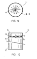
- FIGS 9 and 10 show a second embodiment very similar to that described above with reference to Figures 1 to 8 ; in this case, the triangular teeth 5 are replaced by slots 9.
- the slots 9 of one of the parts 2, 3 enter the spaces delimited by adjacent slots 9 of the other room 3, 2 and vice versa.
- the invention provides means for opening / closing a duct delimited by two parts, having the decisive advantages of being both inexpensive to manufacture, simple to handle and perfectly sealed, and to have an original operation, likely to be attractive to a consumer.
- the invention has been described above with reference to embodiments given as pure examples. It goes without saying that it is not limited to these embodiments but that it extends to all forms of embodiments covered by the appended claims.
- the invention is not limited to an application to the opening / closing of a container, but can find other applications, such as an application to the closure of a pipe or pipe engaged through the parts aforementioned conduit, the sleeve coming, during its twisting, exert a constriction of said conduit or pipe, ensuring the closure of the latter, or an application to the realization of a seal with respect to a part engaged through said duct parts the means according to the invention then forming a "gland".
Landscapes
- Engineering & Computer Science (AREA)
- General Engineering & Computer Science (AREA)
- Mechanical Engineering (AREA)
- Pipe Accessories (AREA)
- Package Closures (AREA)
- Closures For Containers (AREA)
Claims (7)
- Mittel zum Öffnen/Schließen eines durch zwei Teile (2, 3) abgegrenzten Rohrkanals mit:- zwei koaxialen Rohrkanalteilen (2, 3), von denen wenigstens eines relativ zum anderen in Axialrichtung beweglich und zur Rohrkanalachse schwenkbar ist,- Mitteln (5, 9) zur Positionierung der Rohrkanalteile (2, 3), welche das Halten der Rohrkanalteile (2, 3) zueinander in einer Schließstellung des Rohrkanals erlauben, und- einer Manschette (4) aus einem flexiblen Material, welche die beiden Rohrkanalteile (2, 3) verbindet und durch Verdrehen zwischen einem verdrehten Zustand, in welchem sie den Rohrkanal verschließt, und einem nicht verdrehten Zustand, in welchem sie den Rohrkanal freigibt, verformt werden kann,
dadurch gekennzeichnet, dass- die Positionierelemente in Form zweier Folgen von Einstellelementen (5, 9) ausgebildet sind, welche auf den jeweiligen Rändern der beiden Rohrkanalteile (2, 3) gegenüber einander angeordnet sind, wobei die Einstellelemente (5, 9) einer Folge mit den Einstellelementen (5, 9) der anderen Folge in einer Vielzahl von Winkelstellungen zueinander in Eingriff kommen und die Rohrkanalteile (2, 3) in wenigstens zwei Positionen einstellen können, nämlich einer Schließstellung des Rohrkanals und wenigstens einer wenigstens teilweisen Öffnungsstellung des Rohrkanals, und- die Manschette (4) aus einem elastischen Material besteht und in axialer Richtung zwischen einer Normalstellung, in welcher sie die beiden Rohrkanalteile (2, 3) in einer einander angenäherten Position hält, wobei die jeweiligen Einstellelemente (5, 9) in dieser Stellung in Eingriff miteinander stehen, und einer auseinander gezogenen Stellung, in welcher die beiden Rohrkanalteile (2, 3) sich in einer voneinander entfernten Stellung befinden und die jeweiligen Einstellelemente (5, 9) außer Eingriff stehen, was das Verschwenken eines Rohrkanalteils (2, 3) gegenüber dem anderen erlaubt, elastisch verformt werden kann. - Mittel nach Anspruch 1, dadurch gekennzeichnet, dass die Einstellelemente (5, 9) so ausgebildet sind, dass sie die Einstellung der Rohrkanalteile (2, 3) in wenigstens einer Zwischenstellung zwischen der zumindest teilweisen Öffnungsstellung des Rohrkanals und der Schließstellung des Rohrkanals erlauben.
- Mittel nach Anspruch 2, dadurch gekennzeichnet, dass die Einstellelemente (5, 9) so ausgebildet sind, dass sie die Einstellung der Rohrkanalteile (2, 3) in einer Vielzahl von Zwischenstellungen erlauben.
- Mittel nach einem der Ansprüche 1 bis 3, dadurch gekennzeichnet, dass die Einstellelemente in Form von auf den Rändern der beiden Rohrkanalteile (2, 3) gegenüber angeordneten Zahnkränzen (5) ausgebildet sind, wobei die Zähne (5) in der angenäherten Stellung der beiden Rohrkanalteile (2, 3) ineinander greifen.
- Mittel nach einem der Ansprüche 1 bis 3, dadurch gekennzeichnet, dass die Einstellelemente auf den Rändern der beiden Rohrkanalteile (2, 3) gegenüber angeordnete Rechteckzinnen (9) aufweisen, wobei die Rechteckzinnen (9) in der angenäherten Stellung der beiden Rohrkanalteile (2, 3) ineinander greifen.
- Mittel nach einem der Ansprüche 1 bis 5, dadurch gekennzeichnet, dass die Rohrkanalteile (2, 3) Markierungen (6, 7, 8) aufweisen, welche die verdrehte und die nicht verdrehte Stellung der Manschette (4) und somit die zumindest teilweise Öffnungsstellung des Rohrkanals und der Schließstellung des Rohrkanals anzeigen.
- Mittel nach einem der Ansprüche 1 bis 6, dadurch gekennzeichnet, dass das eine der Rohrkanalteile (2, 3) einen Behälterkörper (1) und das andere Rohrkanalteil an einem Ende des Behälterkörpers einen Stellring für das Öffnen und Schließen des Behälters (1) bildet.
Applications Claiming Priority (1)
| Application Number | Priority Date | Filing Date | Title |
|---|---|---|---|
| FR0707223A FR2922195A1 (fr) | 2007-10-16 | 2007-10-16 | Moyens d'ouverture/fermeture d'un conduit delimite par deux pieces. |
Publications (2)
| Publication Number | Publication Date |
|---|---|
| EP2050679A1 EP2050679A1 (de) | 2009-04-22 |
| EP2050679B1 true EP2050679B1 (de) | 2010-06-02 |
Family
ID=39295906
Family Applications (1)
| Application Number | Title | Priority Date | Filing Date |
|---|---|---|---|
| EP08165950A Ceased EP2050679B1 (de) | 2007-10-16 | 2008-10-06 | Öffnungs-/Schließmittel einer Rohrleitung, die durch zwei Teile begrenzt ist |
Country Status (4)
| Country | Link |
|---|---|
| EP (1) | EP2050679B1 (de) |
| AT (1) | ATE469835T1 (de) |
| DE (1) | DE602008001420D1 (de) |
| FR (1) | FR2922195A1 (de) |
Families Citing this family (5)
| Publication number | Priority date | Publication date | Assignee | Title |
|---|---|---|---|---|
| FR2988079B1 (fr) | 2012-03-16 | 2014-04-25 | Neolid | Recipient, notamment a usage alimentaire |
| JP6179781B2 (ja) * | 2013-03-11 | 2017-08-16 | ネオリド | 特に食品用の容器 |
| FR3004425B1 (fr) * | 2013-04-16 | 2015-05-15 | Neolid | Recipient, notamment a usage alimentaire |
| FR3004426B1 (fr) * | 2013-04-16 | 2015-05-15 | Neolid | Recipient, notamment a usage alimentaire |
| FR3016354B1 (fr) * | 2014-01-13 | 2016-02-05 | Neolid | Recipient, notamment a usage alimentaire |
Family Cites Families (4)
| Publication number | Priority date | Publication date | Assignee | Title |
|---|---|---|---|---|
| US1431918A (en) * | 1921-08-10 | 1922-10-17 | Arthur Ernest Lemwel | Bag |
| US2474120A (en) * | 1946-10-01 | 1949-06-21 | Jr Herbert Rumsey | Package |
| US3556390A (en) * | 1969-03-24 | 1971-01-19 | Design Properties Inc | Package for article such as frankfurters |
| US5165593A (en) * | 1992-02-21 | 1992-11-24 | Emily Chuang | Packing box with a unitary, resealable cap |
-
2007
- 2007-10-16 FR FR0707223A patent/FR2922195A1/fr not_active Withdrawn
-
2008
- 2008-10-06 EP EP08165950A patent/EP2050679B1/de not_active Ceased
- 2008-10-06 AT AT08165950T patent/ATE469835T1/de not_active IP Right Cessation
- 2008-10-06 DE DE602008001420T patent/DE602008001420D1/de active Active
Also Published As
| Publication number | Publication date |
|---|---|
| EP2050679A1 (de) | 2009-04-22 |
| FR2922195A1 (fr) | 2009-04-17 |
| DE602008001420D1 (de) | 2010-07-15 |
| ATE469835T1 (de) | 2010-06-15 |
Similar Documents
| Publication | Publication Date | Title |
|---|---|---|
| EP2050679B1 (de) | Öffnungs-/Schließmittel einer Rohrleitung, die durch zwei Teile begrenzt ist | |
| EP3014162B1 (de) | Neutraler fluidstecker mit klammer und schutz | |
| CA2843149C (fr) | Connecteurs a flux direct anti-goutte et a verrouillage securise | |
| FR2855859A1 (fr) | Bague de protection pour le montage | |
| FR2688860A1 (fr) | Organe de drainage etanche pour circuit hydraulique. | |
| CH707634A2 (fr) | Dispositif étanche et pièce d'horlogerie portable. | |
| EP0549450A1 (de) | Handschuhhalteeinrichtung für Isolierraum | |
| EP3531965B1 (de) | Medizinische verpackung | |
| FR3007818A1 (fr) | Connecteur fluidique avec serrage de tube integre. | |
| FR3069420B1 (fr) | Boitier pour produit cosmetique | |
| EP0653825A1 (de) | Abgedichtete Durchführung mit einer biegsamen Membrane und einem Wegwerfdeckel | |
| FR2836354A1 (fr) | Dispositif de protection, de presentation et d'utilisation a des fins d'ornementation courante d'une piece de monnaie | |
| CH700722B1 (fr) | Appareil horaire portable. | |
| EP0897679A1 (de) | Dose mit lösbarem Scharnier und Dichtungslippe | |
| FR2615580A1 (fr) | Garniture d'etancheite a anneau de reaction incorpore, notamment pour obturateur | |
| EP3014158B1 (de) | Fluidstecker mit klemme und schutz | |
| EP2253298A1 (de) | Verbinder für einen flexiblen Behälter zur Aufnahme von medizinischer Flüssigkeit | |
| EP1219881A1 (de) | Auf einer Wand blind befestigtes Element | |
| FR2590642A1 (fr) | Robinet distributeur amovible pour conteneur de liquide | |
| FR2788582A1 (fr) | Dispositif de branchement d'une canalisation de derivation sur une canalisation de transport de fluide | |
| FR2683141A1 (fr) | Dispositif de raccordement de protheses de vaisseaux organiques. | |
| FR3056280A1 (fr) | Embout pour gaine tubulaire de matiere plastique souple | |
| FR2881718A1 (fr) | Dispositif de fermeture de distribution destine a un recipient | |
| CH671004A5 (de) | ||
| FR2807739A1 (fr) | Pot remplissable par le bas |
Legal Events
| Date | Code | Title | Description |
|---|---|---|---|
| PUAI | Public reference made under article 153(3) epc to a published international application that has entered the european phase |
Free format text: ORIGINAL CODE: 0009012 |
|
| AK | Designated contracting states |
Kind code of ref document: A1 Designated state(s): AT BE BG CH CY CZ DE DK EE ES FI FR GB GR HR HU IE IS IT LI LT LU LV MC MT NL NO PL PT RO SE SI SK TR |
|
| AX | Request for extension of the european patent |
Extension state: AL BA MK RS |
|
| 17P | Request for examination filed |
Effective date: 20090921 |
|
| GRAP | Despatch of communication of intention to grant a patent |
Free format text: ORIGINAL CODE: EPIDOSNIGR1 |
|
| AKX | Designation fees paid |
Designated state(s): AT BE BG CH CY CZ LI |
|
| RBV | Designated contracting states (corrected) |
Designated state(s): AT BE BG CH CY CZ DE DK EE ES FI FR GB GR HR HU IE IS IT LI LT LU LV MC MT NL NO PL PT RO SE SI SK TR |
|
| REG | Reference to a national code |
Ref country code: DE Ref legal event code: 8566 |
|
| GRAS | Grant fee paid |
Free format text: ORIGINAL CODE: EPIDOSNIGR3 |
|
| GRAA | (expected) grant |
Free format text: ORIGINAL CODE: 0009210 |
|
| AK | Designated contracting states |
Kind code of ref document: B1 Designated state(s): AT BE BG CH CY CZ DE DK EE ES FI FR GB GR HR HU IE IS IT LI LT LU LV MC MT NL NO PL PT RO SE SI SK TR |
|
| REG | Reference to a national code |
Ref country code: GB Ref legal event code: FG4D Free format text: NOT ENGLISH |
|
| REG | Reference to a national code |
Ref country code: CH Ref legal event code: EP |
|
| REG | Reference to a national code |
Ref country code: IE Ref legal event code: FG4D Free format text: LANGUAGE OF EP DOCUMENT: FRENCH |
|
| REF | Corresponds to: |
Ref document number: 602008001420 Country of ref document: DE Date of ref document: 20100715 Kind code of ref document: P |
|
| REG | Reference to a national code |
Ref country code: CH Ref legal event code: NV Representative=s name: ABREMA AGENCE BREVET ET MARQUES, GANGUILLET |
|
| REG | Reference to a national code |
Ref country code: NL Ref legal event code: VDEP Effective date: 20100602 |
|
| PG25 | Lapsed in a contracting state [announced via postgrant information from national office to epo] |
Ref country code: NO Free format text: LAPSE BECAUSE OF FAILURE TO SUBMIT A TRANSLATION OF THE DESCRIPTION OR TO PAY THE FEE WITHIN THE PRESCRIBED TIME-LIMIT Effective date: 20100902 Ref country code: SE Free format text: LAPSE BECAUSE OF FAILURE TO SUBMIT A TRANSLATION OF THE DESCRIPTION OR TO PAY THE FEE WITHIN THE PRESCRIBED TIME-LIMIT Effective date: 20100602 Ref country code: LT Free format text: LAPSE BECAUSE OF FAILURE TO SUBMIT A TRANSLATION OF THE DESCRIPTION OR TO PAY THE FEE WITHIN THE PRESCRIBED TIME-LIMIT Effective date: 20100602 |
|
| LTIE | Lt: invalidation of european patent or patent extension |
Effective date: 20100602 |
|
| PG25 | Lapsed in a contracting state [announced via postgrant information from national office to epo] |
Ref country code: HR Free format text: LAPSE BECAUSE OF FAILURE TO SUBMIT A TRANSLATION OF THE DESCRIPTION OR TO PAY THE FEE WITHIN THE PRESCRIBED TIME-LIMIT Effective date: 20100602 Ref country code: AT Free format text: LAPSE BECAUSE OF FAILURE TO SUBMIT A TRANSLATION OF THE DESCRIPTION OR TO PAY THE FEE WITHIN THE PRESCRIBED TIME-LIMIT Effective date: 20100602 Ref country code: FI Free format text: LAPSE BECAUSE OF FAILURE TO SUBMIT A TRANSLATION OF THE DESCRIPTION OR TO PAY THE FEE WITHIN THE PRESCRIBED TIME-LIMIT Effective date: 20100602 Ref country code: LV Free format text: LAPSE BECAUSE OF FAILURE TO SUBMIT A TRANSLATION OF THE DESCRIPTION OR TO PAY THE FEE WITHIN THE PRESCRIBED TIME-LIMIT Effective date: 20100602 Ref country code: SI Free format text: LAPSE BECAUSE OF FAILURE TO SUBMIT A TRANSLATION OF THE DESCRIPTION OR TO PAY THE FEE WITHIN THE PRESCRIBED TIME-LIMIT Effective date: 20100602 |
|
| PG25 | Lapsed in a contracting state [announced via postgrant information from national office to epo] |
Ref country code: PL Free format text: LAPSE BECAUSE OF FAILURE TO SUBMIT A TRANSLATION OF THE DESCRIPTION OR TO PAY THE FEE WITHIN THE PRESCRIBED TIME-LIMIT Effective date: 20100602 Ref country code: CY Free format text: LAPSE BECAUSE OF FAILURE TO SUBMIT A TRANSLATION OF THE DESCRIPTION OR TO PAY THE FEE WITHIN THE PRESCRIBED TIME-LIMIT Effective date: 20100609 |
|
| REG | Reference to a national code |
Ref country code: IE Ref legal event code: FD4D |
|
| PG25 | Lapsed in a contracting state [announced via postgrant information from national office to epo] |
Ref country code: EE Free format text: LAPSE BECAUSE OF FAILURE TO SUBMIT A TRANSLATION OF THE DESCRIPTION OR TO PAY THE FEE WITHIN THE PRESCRIBED TIME-LIMIT Effective date: 20100602 Ref country code: IE Free format text: LAPSE BECAUSE OF FAILURE TO SUBMIT A TRANSLATION OF THE DESCRIPTION OR TO PAY THE FEE WITHIN THE PRESCRIBED TIME-LIMIT Effective date: 20100602 Ref country code: NL Free format text: LAPSE BECAUSE OF FAILURE TO SUBMIT A TRANSLATION OF THE DESCRIPTION OR TO PAY THE FEE WITHIN THE PRESCRIBED TIME-LIMIT Effective date: 20100602 |
|
| PG25 | Lapsed in a contracting state [announced via postgrant information from national office to epo] |
Ref country code: SK Free format text: LAPSE BECAUSE OF FAILURE TO SUBMIT A TRANSLATION OF THE DESCRIPTION OR TO PAY THE FEE WITHIN THE PRESCRIBED TIME-LIMIT Effective date: 20100602 Ref country code: IS Free format text: LAPSE BECAUSE OF FAILURE TO SUBMIT A TRANSLATION OF THE DESCRIPTION OR TO PAY THE FEE WITHIN THE PRESCRIBED TIME-LIMIT Effective date: 20101002 Ref country code: RO Free format text: LAPSE BECAUSE OF FAILURE TO SUBMIT A TRANSLATION OF THE DESCRIPTION OR TO PAY THE FEE WITHIN THE PRESCRIBED TIME-LIMIT Effective date: 20100602 Ref country code: CZ Free format text: LAPSE BECAUSE OF FAILURE TO SUBMIT A TRANSLATION OF THE DESCRIPTION OR TO PAY THE FEE WITHIN THE PRESCRIBED TIME-LIMIT Effective date: 20100602 |
|
| PG25 | Lapsed in a contracting state [announced via postgrant information from national office to epo] |
Ref country code: IT Free format text: LAPSE BECAUSE OF FAILURE TO SUBMIT A TRANSLATION OF THE DESCRIPTION OR TO PAY THE FEE WITHIN THE PRESCRIBED TIME-LIMIT Effective date: 20100602 |
|
| PLBE | No opposition filed within time limit |
Free format text: ORIGINAL CODE: 0009261 |
|
| STAA | Information on the status of an ep patent application or granted ep patent |
Free format text: STATUS: NO OPPOSITION FILED WITHIN TIME LIMIT |
|
| PG25 | Lapsed in a contracting state [announced via postgrant information from national office to epo] |
Ref country code: DK Free format text: LAPSE BECAUSE OF FAILURE TO SUBMIT A TRANSLATION OF THE DESCRIPTION OR TO PAY THE FEE WITHIN THE PRESCRIBED TIME-LIMIT Effective date: 20100602 |
|
| BERE | Be: lapsed |
Owner name: FROLIN, NICOLAS Effective date: 20101031 |
|
| 26N | No opposition filed |
Effective date: 20110303 |
|
| PG25 | Lapsed in a contracting state [announced via postgrant information from national office to epo] |
Ref country code: GR Free format text: LAPSE BECAUSE OF FAILURE TO SUBMIT A TRANSLATION OF THE DESCRIPTION OR TO PAY THE FEE WITHIN THE PRESCRIBED TIME-LIMIT Effective date: 20100903 Ref country code: MC Free format text: LAPSE BECAUSE OF NON-PAYMENT OF DUE FEES Effective date: 20101031 |
|
| REG | Reference to a national code |
Ref country code: DE Ref legal event code: R097 Ref document number: 602008001420 Country of ref document: DE Effective date: 20110302 |
|
| PG25 | Lapsed in a contracting state [announced via postgrant information from national office to epo] |
Ref country code: BE Free format text: LAPSE BECAUSE OF NON-PAYMENT OF DUE FEES Effective date: 20101031 |
|
| PG25 | Lapsed in a contracting state [announced via postgrant information from national office to epo] |
Ref country code: MT Free format text: LAPSE BECAUSE OF FAILURE TO SUBMIT A TRANSLATION OF THE DESCRIPTION OR TO PAY THE FEE WITHIN THE PRESCRIBED TIME-LIMIT Effective date: 20100602 |
|
| PG25 | Lapsed in a contracting state [announced via postgrant information from national office to epo] |
Ref country code: LU Free format text: LAPSE BECAUSE OF NON-PAYMENT OF DUE FEES Effective date: 20101006 Ref country code: BG Free format text: LAPSE BECAUSE OF FAILURE TO SUBMIT A TRANSLATION OF THE DESCRIPTION OR TO PAY THE FEE WITHIN THE PRESCRIBED TIME-LIMIT Effective date: 20100602 Ref country code: HU Free format text: LAPSE BECAUSE OF FAILURE TO SUBMIT A TRANSLATION OF THE DESCRIPTION OR TO PAY THE FEE WITHIN THE PRESCRIBED TIME-LIMIT Effective date: 20101203 |
|
| PG25 | Lapsed in a contracting state [announced via postgrant information from national office to epo] |
Ref country code: TR Free format text: LAPSE BECAUSE OF FAILURE TO SUBMIT A TRANSLATION OF THE DESCRIPTION OR TO PAY THE FEE WITHIN THE PRESCRIBED TIME-LIMIT Effective date: 20100602 |
|
| GBPC | Gb: european patent ceased through non-payment of renewal fee |
Effective date: 20121006 |
|
| PG25 | Lapsed in a contracting state [announced via postgrant information from national office to epo] |
Ref country code: PT Free format text: LAPSE BECAUSE OF NON-PAYMENT OF DUE FEES Effective date: 20100602 Ref country code: GB Free format text: LAPSE BECAUSE OF NON-PAYMENT OF DUE FEES Effective date: 20121006 |
|
| PG25 | Lapsed in a contracting state [announced via postgrant information from national office to epo] |
Ref country code: BG Free format text: LAPSE BECAUSE OF FAILURE TO SUBMIT A TRANSLATION OF THE DESCRIPTION OR TO PAY THE FEE WITHIN THE PRESCRIBED TIME-LIMIT Effective date: 20100902 |
|
| PG25 | Lapsed in a contracting state [announced via postgrant information from national office to epo] |
Ref country code: ES Free format text: LAPSE BECAUSE OF FAILURE TO SUBMIT A TRANSLATION OF THE DESCRIPTION OR TO PAY THE FEE WITHIN THE PRESCRIBED TIME-LIMIT Effective date: 20100913 |
|
| REG | Reference to a national code |
Ref country code: FR Ref legal event code: PLFP Year of fee payment: 9 |
|
| REG | Reference to a national code |
Ref country code: FR Ref legal event code: PLFP Year of fee payment: 10 |
|
| PGFP | Annual fee paid to national office [announced via postgrant information from national office to epo] |
Ref country code: DE Payment date: 20171121 Year of fee payment: 10 |
|
| PGFP | Annual fee paid to national office [announced via postgrant information from national office to epo] |
Ref country code: CH Payment date: 20171120 Year of fee payment: 10 |
|
| REG | Reference to a national code |
Ref country code: FR Ref legal event code: PLFP Year of fee payment: 11 |
|
| PGFP | Annual fee paid to national office [announced via postgrant information from national office to epo] |
Ref country code: FR Payment date: 20181031 Year of fee payment: 11 |
|
| REG | Reference to a national code |
Ref country code: DE Ref legal event code: R119 Ref document number: 602008001420 Country of ref document: DE |
|
| REG | Reference to a national code |
Ref country code: CH Ref legal event code: PL |
|
| PG25 | Lapsed in a contracting state [announced via postgrant information from national office to epo] |
Ref country code: DE Free format text: LAPSE BECAUSE OF NON-PAYMENT OF DUE FEES Effective date: 20190501 |
|
| PG25 | Lapsed in a contracting state [announced via postgrant information from national office to epo] |
Ref country code: CH Free format text: LAPSE BECAUSE OF NON-PAYMENT OF DUE FEES Effective date: 20181031 Ref country code: LI Free format text: LAPSE BECAUSE OF NON-PAYMENT OF DUE FEES Effective date: 20181031 |
|
| PG25 | Lapsed in a contracting state [announced via postgrant information from national office to epo] |
Ref country code: FR Free format text: LAPSE BECAUSE OF NON-PAYMENT OF DUE FEES Effective date: 20191031 |