EP2050726A2 - Composition céramique piézoélectrique/électrostrictif et dispositif piézoélectrique/électrostrictif - Google Patents
Composition céramique piézoélectrique/électrostrictif et dispositif piézoélectrique/électrostrictif Download PDFInfo
- Publication number
- EP2050726A2 EP2050726A2 EP08253384A EP08253384A EP2050726A2 EP 2050726 A2 EP2050726 A2 EP 2050726A2 EP 08253384 A EP08253384 A EP 08253384A EP 08253384 A EP08253384 A EP 08253384A EP 2050726 A2 EP2050726 A2 EP 2050726A2
- Authority
- EP
- European Patent Office
- Prior art keywords
- piezoelectric
- electrostrictive
- elements
- ceramic composition
- film
- Prior art date
- Legal status (The legal status is an assumption and is not a legal conclusion. Google has not performed a legal analysis and makes no representation as to the accuracy of the status listed.)
- Withdrawn
Links
- 239000000203 mixture Substances 0.000 title claims abstract description 77
- 239000000919 ceramic Substances 0.000 title claims abstract description 72
- 229910052700 potassium Inorganic materials 0.000 claims abstract description 19
- 229910052744 lithium Inorganic materials 0.000 claims abstract description 18
- 229910052708 sodium Inorganic materials 0.000 claims abstract description 18
- 229910052758 niobium Inorganic materials 0.000 claims abstract description 16
- 229910052715 tantalum Inorganic materials 0.000 claims abstract description 15
- 229910012599 Li3NbO4 Inorganic materials 0.000 claims description 27
- 230000005684 electric field Effects 0.000 abstract description 30
- 239000011734 sodium Substances 0.000 abstract description 23
- 239000010955 niobium Substances 0.000 abstract description 20
- QVGXLLKOCUKJST-UHFFFAOYSA-N atomic oxygen Chemical compound [O] QVGXLLKOCUKJST-UHFFFAOYSA-N 0.000 abstract description 5
- 229910052760 oxygen Inorganic materials 0.000 abstract description 5
- 239000001301 oxygen Substances 0.000 abstract description 5
- DGAQECJNVWCQMB-PUAWFVPOSA-M Ilexoside XXIX Chemical compound C[C@@H]1CC[C@@]2(CC[C@@]3(C(=CC[C@H]4[C@]3(CC[C@@H]5[C@@]4(CC[C@@H](C5(C)C)OS(=O)(=O)[O-])C)C)[C@@H]2[C@]1(C)O)C)C(=O)O[C@H]6[C@@H]([C@H]([C@@H]([C@H](O6)CO)O)O)O.[Na+] DGAQECJNVWCQMB-PUAWFVPOSA-M 0.000 abstract description 2
- WHXSMMKQMYFTQS-UHFFFAOYSA-N Lithium Chemical compound [Li] WHXSMMKQMYFTQS-UHFFFAOYSA-N 0.000 abstract description 2
- ZLMJMSJWJFRBEC-UHFFFAOYSA-N Potassium Chemical compound [K] ZLMJMSJWJFRBEC-UHFFFAOYSA-N 0.000 abstract description 2
- GUCVJGMIXFAOAE-UHFFFAOYSA-N niobium atom Chemical compound [Nb] GUCVJGMIXFAOAE-UHFFFAOYSA-N 0.000 abstract description 2
- 239000011591 potassium Substances 0.000 abstract description 2
- GUVRBAGPIYLISA-UHFFFAOYSA-N tantalum atom Chemical compound [Ta] GUVRBAGPIYLISA-UHFFFAOYSA-N 0.000 abstract description 2
- 238000010304 firing Methods 0.000 description 42
- 239000012071 phase Substances 0.000 description 41
- 239000011572 manganese Substances 0.000 description 36
- 239000000758 substrate Substances 0.000 description 29
- 230000007704 transition Effects 0.000 description 29
- 230000000052 comparative effect Effects 0.000 description 25
- 150000001875 compounds Chemical class 0.000 description 19
- 239000000843 powder Substances 0.000 description 18
- 238000000034 method Methods 0.000 description 16
- 238000000691 measurement method Methods 0.000 description 15
- 238000005245 sintering Methods 0.000 description 15
- 238000002441 X-ray diffraction Methods 0.000 description 14
- 239000002003 electrode paste Substances 0.000 description 12
- 238000005259 measurement Methods 0.000 description 12
- BASFCYQUMIYNBI-UHFFFAOYSA-N platinum Chemical compound [Pt] BASFCYQUMIYNBI-UHFFFAOYSA-N 0.000 description 12
- 239000013078 crystal Substances 0.000 description 10
- NUJOXMJBOLGQSY-UHFFFAOYSA-N manganese dioxide Chemical compound O=[Mn]=O NUJOXMJBOLGQSY-UHFFFAOYSA-N 0.000 description 10
- 238000004519 manufacturing process Methods 0.000 description 10
- RVTZCBVAJQQJTK-UHFFFAOYSA-N oxygen(2-);zirconium(4+) Chemical compound [O-2].[O-2].[Zr+4] RVTZCBVAJQQJTK-UHFFFAOYSA-N 0.000 description 10
- 239000007858 starting material Substances 0.000 description 10
- 229910001928 zirconium oxide Inorganic materials 0.000 description 10
- RKTYLMNFRDHKIL-UHFFFAOYSA-N copper;5,10,15,20-tetraphenylporphyrin-22,24-diide Chemical compound [Cu+2].C1=CC(C(=C2C=CC([N-]2)=C(C=2C=CC=CC=2)C=2C=CC(N=2)=C(C=2C=CC=CC=2)C2=CC=C3[N-]2)C=2C=CC=CC=2)=NC1=C3C1=CC=CC=C1 RKTYLMNFRDHKIL-UHFFFAOYSA-N 0.000 description 8
- 238000006073 displacement reaction Methods 0.000 description 8
- 239000002245 particle Substances 0.000 description 8
- 238000010438 heat treatment Methods 0.000 description 7
- 230000010287 polarization Effects 0.000 description 7
- 239000000956 alloy Substances 0.000 description 6
- 229910045601 alloy Inorganic materials 0.000 description 6
- 239000002612 dispersion medium Substances 0.000 description 6
- 238000011156 evaluation Methods 0.000 description 6
- 239000010410 layer Substances 0.000 description 6
- 229910052697 platinum Inorganic materials 0.000 description 6
- 238000007650 screen-printing Methods 0.000 description 6
- PCHJSUWPFVWCPO-UHFFFAOYSA-N gold Chemical compound [Au] PCHJSUWPFVWCPO-UHFFFAOYSA-N 0.000 description 5
- 229910052737 gold Inorganic materials 0.000 description 5
- 239000010931 gold Substances 0.000 description 5
- 238000009413 insulation Methods 0.000 description 5
- 239000000463 material Substances 0.000 description 5
- 239000002356 single layer Substances 0.000 description 5
- 238000004544 sputter deposition Methods 0.000 description 5
- KDLHZDBZIXYQEI-UHFFFAOYSA-N Palladium Chemical compound [Pd] KDLHZDBZIXYQEI-UHFFFAOYSA-N 0.000 description 4
- 230000008901 benefit Effects 0.000 description 4
- 238000005229 chemical vapour deposition Methods 0.000 description 4
- AMWRITDGCCNYAT-UHFFFAOYSA-L hydroxy(oxo)manganese;manganese Chemical compound [Mn].O[Mn]=O.O[Mn]=O AMWRITDGCCNYAT-UHFFFAOYSA-L 0.000 description 4
- SIWVEOZUMHYXCS-UHFFFAOYSA-N oxo(oxoyttriooxy)yttrium Chemical compound O=[Y]O[Y]=O SIWVEOZUMHYXCS-UHFFFAOYSA-N 0.000 description 4
- 238000005240 physical vapour deposition Methods 0.000 description 4
- 239000006104 solid solution Substances 0.000 description 4
- LFQSCWFLJHTTHZ-UHFFFAOYSA-N Ethanol Chemical compound CCO LFQSCWFLJHTTHZ-UHFFFAOYSA-N 0.000 description 3
- BQCADISMDOOEFD-UHFFFAOYSA-N Silver Chemical compound [Ag] BQCADISMDOOEFD-UHFFFAOYSA-N 0.000 description 3
- YXFVVABEGXRONW-UHFFFAOYSA-N Toluene Chemical compound CC1=CC=CC=C1 YXFVVABEGXRONW-UHFFFAOYSA-N 0.000 description 3
- 239000000853 adhesive Substances 0.000 description 3
- 230000001070 adhesive effect Effects 0.000 description 3
- 239000012298 atmosphere Substances 0.000 description 3
- 230000015556 catabolic process Effects 0.000 description 3
- 238000000280 densification Methods 0.000 description 3
- 238000001704 evaporation Methods 0.000 description 3
- 230000008020 evaporation Effects 0.000 description 3
- 229910052751 metal Inorganic materials 0.000 description 3
- 239000002184 metal Substances 0.000 description 3
- 229910052709 silver Inorganic materials 0.000 description 3
- 239000004332 silver Substances 0.000 description 3
- 238000003746 solid phase reaction Methods 0.000 description 3
- 239000003381 stabilizer Substances 0.000 description 3
- CSCPPACGZOOCGX-UHFFFAOYSA-N Acetone Chemical compound CC(C)=O CSCPPACGZOOCGX-UHFFFAOYSA-N 0.000 description 2
- 229910012463 LiTaO3 Inorganic materials 0.000 description 2
- PWHULOQIROXLJO-UHFFFAOYSA-N Manganese Chemical compound [Mn] PWHULOQIROXLJO-UHFFFAOYSA-N 0.000 description 2
- 229910020279 Pb(Zr, Ti)O3 Inorganic materials 0.000 description 2
- 229910001252 Pd alloy Inorganic materials 0.000 description 2
- 238000004998 X ray absorption near edge structure spectroscopy Methods 0.000 description 2
- 239000000443 aerosol Substances 0.000 description 2
- 239000003513 alkali Substances 0.000 description 2
- 230000015572 biosynthetic process Effects 0.000 description 2
- 229910000420 cerium oxide Inorganic materials 0.000 description 2
- 238000000151 deposition Methods 0.000 description 2
- 230000008021 deposition Effects 0.000 description 2
- 238000007598 dipping method Methods 0.000 description 2
- 239000002270 dispersing agent Substances 0.000 description 2
- 238000007606 doctor blade method Methods 0.000 description 2
- 230000000694 effects Effects 0.000 description 2
- 239000011521 glass Substances 0.000 description 2
- 238000007733 ion plating Methods 0.000 description 2
- 238000010884 ion-beam technique Methods 0.000 description 2
- 238000003475 lamination Methods 0.000 description 2
- 239000000395 magnesium oxide Substances 0.000 description 2
- CPLXHLVBOLITMK-UHFFFAOYSA-N magnesium oxide Inorganic materials [Mg]=O CPLXHLVBOLITMK-UHFFFAOYSA-N 0.000 description 2
- AXZKOIWUVFPNLO-UHFFFAOYSA-N magnesium;oxygen(2-) Chemical compound [O-2].[Mg+2] AXZKOIWUVFPNLO-UHFFFAOYSA-N 0.000 description 2
- 150000002739 metals Chemical class 0.000 description 2
- TWNQGVIAIRXVLR-UHFFFAOYSA-N oxo(oxoalumanyloxy)alumane Chemical compound O=[Al]O[Al]=O TWNQGVIAIRXVLR-UHFFFAOYSA-N 0.000 description 2
- 229910052763 palladium Inorganic materials 0.000 description 2
- SWELZOZIOHGSPA-UHFFFAOYSA-N palladium silver Chemical compound [Pd].[Ag] SWELZOZIOHGSPA-UHFFFAOYSA-N 0.000 description 2
- 239000004014 plasticizer Substances 0.000 description 2
- 238000007747 plating Methods 0.000 description 2
- 230000008569 process Effects 0.000 description 2
- 229910052703 rhodium Inorganic materials 0.000 description 2
- 239000010948 rhodium Substances 0.000 description 2
- MHOVAHRLVXNVSD-UHFFFAOYSA-N rhodium atom Chemical compound [Rh] MHOVAHRLVXNVSD-UHFFFAOYSA-N 0.000 description 2
- 229920006395 saturated elastomer Polymers 0.000 description 2
- 239000002002 slurry Substances 0.000 description 2
- 238000005507 spraying Methods 0.000 description 2
- 239000000126 substance Substances 0.000 description 2
- 238000007738 vacuum evaporation Methods 0.000 description 2
- 238000007088 Archimedes method Methods 0.000 description 1
- OKTJSMMVPCPJKN-UHFFFAOYSA-N Carbon Chemical compound [C] OKTJSMMVPCPJKN-UHFFFAOYSA-N 0.000 description 1
- 229910052581 Si3N4 Inorganic materials 0.000 description 1
- XUIMIQQOPSSXEZ-UHFFFAOYSA-N Silicon Chemical compound [Si] XUIMIQQOPSSXEZ-UHFFFAOYSA-N 0.000 description 1
- 150000004703 alkoxides Chemical class 0.000 description 1
- 229910052782 aluminium Inorganic materials 0.000 description 1
- XAGFODPZIPBFFR-UHFFFAOYSA-N aluminium Chemical compound [Al] XAGFODPZIPBFFR-UHFFFAOYSA-N 0.000 description 1
- 239000011230 binding agent Substances 0.000 description 1
- 238000001354 calcination Methods 0.000 description 1
- BRPQOXSCLDDYGP-UHFFFAOYSA-N calcium oxide Chemical compound [O-2].[Ca+2] BRPQOXSCLDDYGP-UHFFFAOYSA-N 0.000 description 1
- 239000000292 calcium oxide Substances 0.000 description 1
- ODINCKMPIJJUCX-UHFFFAOYSA-N calcium oxide Inorganic materials [Ca]=O ODINCKMPIJJUCX-UHFFFAOYSA-N 0.000 description 1
- 238000004364 calculation method Methods 0.000 description 1
- 150000004649 carbonic acid derivatives Chemical class 0.000 description 1
- 238000006243 chemical reaction Methods 0.000 description 1
- 238000000975 co-precipitation Methods 0.000 description 1
- 239000002131 composite material Substances 0.000 description 1
- 230000008602 contraction Effects 0.000 description 1
- PMHQVHHXPFUNSP-UHFFFAOYSA-M copper(1+);methylsulfanylmethane;bromide Chemical compound Br[Cu].CSC PMHQVHHXPFUNSP-UHFFFAOYSA-M 0.000 description 1
- 238000009792 diffusion process Methods 0.000 description 1
- KZHJGOXRZJKJNY-UHFFFAOYSA-N dioxosilane;oxo(oxoalumanyloxy)alumane Chemical compound O=[Si]=O.O=[Si]=O.O=[Al]O[Al]=O.O=[Al]O[Al]=O.O=[Al]O[Al]=O KZHJGOXRZJKJNY-UHFFFAOYSA-N 0.000 description 1
- RBQDIMNMXLVMBS-UHFFFAOYSA-L disodium;2,3-dihydroxybutanedioate;hydrate Chemical compound O.[Na+].[Na+].[O-]C(=O)C(O)C(O)C([O-])=O RBQDIMNMXLVMBS-UHFFFAOYSA-L 0.000 description 1
- 238000001035 drying Methods 0.000 description 1
- 238000010828 elution Methods 0.000 description 1
- 238000001914 filtration Methods 0.000 description 1
- -1 first Substances 0.000 description 1
- 229910002804 graphite Inorganic materials 0.000 description 1
- 239000010439 graphite Substances 0.000 description 1
- 230000006872 improvement Effects 0.000 description 1
- XGZVUEUWXADBQD-UHFFFAOYSA-L lithium carbonate Chemical compound [Li+].[Li+].[O-]C([O-])=O XGZVUEUWXADBQD-UHFFFAOYSA-L 0.000 description 1
- 230000014759 maintenance of location Effects 0.000 description 1
- 229910052748 manganese Inorganic materials 0.000 description 1
- 150000002697 manganese compounds Chemical class 0.000 description 1
- 230000008018 melting Effects 0.000 description 1
- 238000002844 melting Methods 0.000 description 1
- 239000011268 mixed slurry Substances 0.000 description 1
- 238000012986 modification Methods 0.000 description 1
- 230000004048 modification Effects 0.000 description 1
- 229910052863 mullite Inorganic materials 0.000 description 1
- URLJKFSTXLNXLG-UHFFFAOYSA-N niobium(5+);oxygen(2-) Chemical compound [O-2].[O-2].[O-2].[O-2].[O-2].[Nb+5].[Nb+5] URLJKFSTXLNXLG-UHFFFAOYSA-N 0.000 description 1
- 239000003921 oil Substances 0.000 description 1
- 239000003960 organic solvent Substances 0.000 description 1
- BMMGVYCKOGBVEV-UHFFFAOYSA-N oxo(oxoceriooxy)cerium Chemical compound [Ce]=O.O=[Ce]=O BMMGVYCKOGBVEV-UHFFFAOYSA-N 0.000 description 1
- BPUBBGLMJRNUCC-UHFFFAOYSA-N oxygen(2-);tantalum(5+) Chemical compound [O-2].[O-2].[O-2].[O-2].[O-2].[Ta+5].[Ta+5] BPUBBGLMJRNUCC-UHFFFAOYSA-N 0.000 description 1
- UZLYXNNZYFBAQO-UHFFFAOYSA-N oxygen(2-);ytterbium(3+) Chemical compound [O-2].[O-2].[O-2].[Yb+3].[Yb+3] UZLYXNNZYFBAQO-UHFFFAOYSA-N 0.000 description 1
- AVTYONGGKAJVTE-OLXYHTOASA-L potassium L-tartrate Chemical compound [K+].[K+].[O-]C(=O)[C@H](O)[C@@H](O)C([O-])=O AVTYONGGKAJVTE-OLXYHTOASA-L 0.000 description 1
- 239000001472 potassium tartrate Substances 0.000 description 1
- 229940111695 potassium tartrate Drugs 0.000 description 1
- 235000011005 potassium tartrates Nutrition 0.000 description 1
- 238000001556 precipitation Methods 0.000 description 1
- 238000004445 quantitative analysis Methods 0.000 description 1
- 229910052761 rare earth metal Inorganic materials 0.000 description 1
- 150000002910 rare earth metals Chemical class 0.000 description 1
- 230000004044 response Effects 0.000 description 1
- 229910052710 silicon Inorganic materials 0.000 description 1
- 239000010703 silicon Substances 0.000 description 1
- HQVNEWCFYHHQES-UHFFFAOYSA-N silicon nitride Chemical compound N12[Si]34N5[Si]62N3[Si]51N64 HQVNEWCFYHHQES-UHFFFAOYSA-N 0.000 description 1
- 239000002904 solvent Substances 0.000 description 1
- 150000003892 tartrate salts Chemical class 0.000 description 1
- 238000007669 thermal treatment Methods 0.000 description 1
- LEONUFNNVUYDNQ-UHFFFAOYSA-N vanadium atom Chemical compound [V] LEONUFNNVUYDNQ-UHFFFAOYSA-N 0.000 description 1
- 229910003454 ytterbium oxide Inorganic materials 0.000 description 1
- 229940075624 ytterbium oxide Drugs 0.000 description 1
Images


Classifications
-
- C—CHEMISTRY; METALLURGY
- C04—CEMENTS; CONCRETE; ARTIFICIAL STONE; CERAMICS; REFRACTORIES
- C04B—LIME, MAGNESIA; SLAG; CEMENTS; COMPOSITIONS THEREOF, e.g. MORTARS, CONCRETE OR LIKE BUILDING MATERIALS; ARTIFICIAL STONE; CERAMICS; REFRACTORIES; TREATMENT OF NATURAL STONE
- C04B35/00—Shaped ceramic products characterised by their composition; Ceramics compositions; Processing powders of inorganic compounds preparatory to the manufacturing of ceramic products
- C04B35/01—Shaped ceramic products characterised by their composition; Ceramics compositions; Processing powders of inorganic compounds preparatory to the manufacturing of ceramic products based on oxide ceramics
- C04B35/495—Shaped ceramic products characterised by their composition; Ceramics compositions; Processing powders of inorganic compounds preparatory to the manufacturing of ceramic products based on oxide ceramics based on vanadium, niobium, tantalum, molybdenum or tungsten oxides or solid solutions thereof with other oxides, e.g. vanadates, niobates, tantalates, molybdates or tungstates
-
- C—CHEMISTRY; METALLURGY
- C01—INORGANIC CHEMISTRY
- C01G—COMPOUNDS CONTAINING METALS NOT COVERED BY SUBCLASSES C01D OR C01F
- C01G23/00—Compounds of titanium
- C01G23/003—Titanates
-
- H—ELECTRICITY
- H10—SEMICONDUCTOR DEVICES; ELECTRIC SOLID-STATE DEVICES NOT OTHERWISE PROVIDED FOR
- H10N—ELECTRIC SOLID-STATE DEVICES NOT OTHERWISE PROVIDED FOR
- H10N30/00—Piezoelectric or electrostrictive devices
- H10N30/80—Constructional details
- H10N30/85—Piezoelectric or electrostrictive active materials
- H10N30/853—Ceramic compositions
- H10N30/8542—Alkali metal based oxides, e.g. lithium, sodium or potassium niobates
-
- C—CHEMISTRY; METALLURGY
- C01—INORGANIC CHEMISTRY
- C01P—INDEXING SCHEME RELATING TO STRUCTURAL AND PHYSICAL ASPECTS OF SOLID INORGANIC COMPOUNDS
- C01P2002/00—Crystal-structural characteristics
- C01P2002/30—Three-dimensional structures
- C01P2002/34—Three-dimensional structures perovskite-type (ABO3)
-
- C—CHEMISTRY; METALLURGY
- C01—INORGANIC CHEMISTRY
- C01P—INDEXING SCHEME RELATING TO STRUCTURAL AND PHYSICAL ASPECTS OF SOLID INORGANIC COMPOUNDS
- C01P2002/00—Crystal-structural characteristics
- C01P2002/70—Crystal-structural characteristics defined by measured X-ray, neutron or electron diffraction data
- C01P2002/72—Crystal-structural characteristics defined by measured X-ray, neutron or electron diffraction data by d-values or two theta-values, e.g. as X-ray diagram
-
- C—CHEMISTRY; METALLURGY
- C01—INORGANIC CHEMISTRY
- C01P—INDEXING SCHEME RELATING TO STRUCTURAL AND PHYSICAL ASPECTS OF SOLID INORGANIC COMPOUNDS
- C01P2006/00—Physical properties of inorganic compounds
- C01P2006/11—Powder tap density
-
- C—CHEMISTRY; METALLURGY
- C01—INORGANIC CHEMISTRY
- C01P—INDEXING SCHEME RELATING TO STRUCTURAL AND PHYSICAL ASPECTS OF SOLID INORGANIC COMPOUNDS
- C01P2006/00—Physical properties of inorganic compounds
- C01P2006/40—Electric properties
-
- C—CHEMISTRY; METALLURGY
- C01—INORGANIC CHEMISTRY
- C01P—INDEXING SCHEME RELATING TO STRUCTURAL AND PHYSICAL ASPECTS OF SOLID INORGANIC COMPOUNDS
- C01P2006/00—Physical properties of inorganic compounds
- C01P2006/80—Compositional purity
-
- C—CHEMISTRY; METALLURGY
- C04—CEMENTS; CONCRETE; ARTIFICIAL STONE; CERAMICS; REFRACTORIES
- C04B—LIME, MAGNESIA; SLAG; CEMENTS; COMPOSITIONS THEREOF, e.g. MORTARS, CONCRETE OR LIKE BUILDING MATERIALS; ARTIFICIAL STONE; CERAMICS; REFRACTORIES; TREATMENT OF NATURAL STONE
- C04B2235/00—Aspects relating to ceramic starting mixtures or sintered ceramic products
- C04B2235/02—Composition of constituents of the starting material or of secondary phases of the final product
- C04B2235/30—Constituents and secondary phases not being of a fibrous nature
- C04B2235/32—Metal oxides, mixed metal oxides, or oxide-forming salts thereof, e.g. carbonates, nitrates, (oxy)hydroxides, chlorides
- C04B2235/3201—Alkali metal oxides or oxide-forming salts thereof
-
- C—CHEMISTRY; METALLURGY
- C04—CEMENTS; CONCRETE; ARTIFICIAL STONE; CERAMICS; REFRACTORIES
- C04B—LIME, MAGNESIA; SLAG; CEMENTS; COMPOSITIONS THEREOF, e.g. MORTARS, CONCRETE OR LIKE BUILDING MATERIALS; ARTIFICIAL STONE; CERAMICS; REFRACTORIES; TREATMENT OF NATURAL STONE
- C04B2235/00—Aspects relating to ceramic starting mixtures or sintered ceramic products
- C04B2235/02—Composition of constituents of the starting material or of secondary phases of the final product
- C04B2235/30—Constituents and secondary phases not being of a fibrous nature
- C04B2235/32—Metal oxides, mixed metal oxides, or oxide-forming salts thereof, e.g. carbonates, nitrates, (oxy)hydroxides, chlorides
- C04B2235/3201—Alkali metal oxides or oxide-forming salts thereof
- C04B2235/3203—Lithium oxide or oxide-forming salts thereof
-
- C—CHEMISTRY; METALLURGY
- C04—CEMENTS; CONCRETE; ARTIFICIAL STONE; CERAMICS; REFRACTORIES
- C04B—LIME, MAGNESIA; SLAG; CEMENTS; COMPOSITIONS THEREOF, e.g. MORTARS, CONCRETE OR LIKE BUILDING MATERIALS; ARTIFICIAL STONE; CERAMICS; REFRACTORIES; TREATMENT OF NATURAL STONE
- C04B2235/00—Aspects relating to ceramic starting mixtures or sintered ceramic products
- C04B2235/02—Composition of constituents of the starting material or of secondary phases of the final product
- C04B2235/30—Constituents and secondary phases not being of a fibrous nature
- C04B2235/32—Metal oxides, mixed metal oxides, or oxide-forming salts thereof, e.g. carbonates, nitrates, (oxy)hydroxides, chlorides
- C04B2235/3231—Refractory metal oxides, their mixed metal oxides, or oxide-forming salts thereof
- C04B2235/3251—Niobium oxides, niobates, tantalum oxides, tantalates, or oxide-forming salts thereof
-
- C—CHEMISTRY; METALLURGY
- C04—CEMENTS; CONCRETE; ARTIFICIAL STONE; CERAMICS; REFRACTORIES
- C04B—LIME, MAGNESIA; SLAG; CEMENTS; COMPOSITIONS THEREOF, e.g. MORTARS, CONCRETE OR LIKE BUILDING MATERIALS; ARTIFICIAL STONE; CERAMICS; REFRACTORIES; TREATMENT OF NATURAL STONE
- C04B2235/00—Aspects relating to ceramic starting mixtures or sintered ceramic products
- C04B2235/02—Composition of constituents of the starting material or of secondary phases of the final product
- C04B2235/30—Constituents and secondary phases not being of a fibrous nature
- C04B2235/32—Metal oxides, mixed metal oxides, or oxide-forming salts thereof, e.g. carbonates, nitrates, (oxy)hydroxides, chlorides
- C04B2235/3231—Refractory metal oxides, their mixed metal oxides, or oxide-forming salts thereof
- C04B2235/3251—Niobium oxides, niobates, tantalum oxides, tantalates, or oxide-forming salts thereof
- C04B2235/3255—Niobates or tantalates, e.g. silver niobate
-
- C—CHEMISTRY; METALLURGY
- C04—CEMENTS; CONCRETE; ARTIFICIAL STONE; CERAMICS; REFRACTORIES
- C04B—LIME, MAGNESIA; SLAG; CEMENTS; COMPOSITIONS THEREOF, e.g. MORTARS, CONCRETE OR LIKE BUILDING MATERIALS; ARTIFICIAL STONE; CERAMICS; REFRACTORIES; TREATMENT OF NATURAL STONE
- C04B2235/00—Aspects relating to ceramic starting mixtures or sintered ceramic products
- C04B2235/02—Composition of constituents of the starting material or of secondary phases of the final product
- C04B2235/30—Constituents and secondary phases not being of a fibrous nature
- C04B2235/44—Metal salt constituents or additives chosen for the nature of the anions, e.g. hydrides or acetylacetonate
- C04B2235/449—Organic acids, e.g. EDTA, citrate, acetate, oxalate
-
- C—CHEMISTRY; METALLURGY
- C04—CEMENTS; CONCRETE; ARTIFICIAL STONE; CERAMICS; REFRACTORIES
- C04B—LIME, MAGNESIA; SLAG; CEMENTS; COMPOSITIONS THEREOF, e.g. MORTARS, CONCRETE OR LIKE BUILDING MATERIALS; ARTIFICIAL STONE; CERAMICS; REFRACTORIES; TREATMENT OF NATURAL STONE
- C04B2235/00—Aspects relating to ceramic starting mixtures or sintered ceramic products
- C04B2235/65—Aspects relating to heat treatments of ceramic bodies such as green ceramics or pre-sintered ceramics, e.g. burning, sintering or melting processes
- C04B2235/656—Aspects relating to heat treatments of ceramic bodies such as green ceramics or pre-sintered ceramics, e.g. burning, sintering or melting processes characterised by specific heating conditions during heat treatment
-
- C—CHEMISTRY; METALLURGY
- C04—CEMENTS; CONCRETE; ARTIFICIAL STONE; CERAMICS; REFRACTORIES
- C04B—LIME, MAGNESIA; SLAG; CEMENTS; COMPOSITIONS THEREOF, e.g. MORTARS, CONCRETE OR LIKE BUILDING MATERIALS; ARTIFICIAL STONE; CERAMICS; REFRACTORIES; TREATMENT OF NATURAL STONE
- C04B2235/00—Aspects relating to ceramic starting mixtures or sintered ceramic products
- C04B2235/70—Aspects relating to sintered or melt-casted ceramic products
- C04B2235/74—Physical characteristics
- C04B2235/76—Crystal structural characteristics, e.g. symmetry
-
- C—CHEMISTRY; METALLURGY
- C04—CEMENTS; CONCRETE; ARTIFICIAL STONE; CERAMICS; REFRACTORIES
- C04B—LIME, MAGNESIA; SLAG; CEMENTS; COMPOSITIONS THEREOF, e.g. MORTARS, CONCRETE OR LIKE BUILDING MATERIALS; ARTIFICIAL STONE; CERAMICS; REFRACTORIES; TREATMENT OF NATURAL STONE
- C04B2235/00—Aspects relating to ceramic starting mixtures or sintered ceramic products
- C04B2235/70—Aspects relating to sintered or melt-casted ceramic products
- C04B2235/74—Physical characteristics
- C04B2235/76—Crystal structural characteristics, e.g. symmetry
- C04B2235/765—Tetragonal symmetry
-
- C—CHEMISTRY; METALLURGY
- C04—CEMENTS; CONCRETE; ARTIFICIAL STONE; CERAMICS; REFRACTORIES
- C04B—LIME, MAGNESIA; SLAG; CEMENTS; COMPOSITIONS THEREOF, e.g. MORTARS, CONCRETE OR LIKE BUILDING MATERIALS; ARTIFICIAL STONE; CERAMICS; REFRACTORIES; TREATMENT OF NATURAL STONE
- C04B2235/00—Aspects relating to ceramic starting mixtures or sintered ceramic products
- C04B2235/70—Aspects relating to sintered or melt-casted ceramic products
- C04B2235/74—Physical characteristics
- C04B2235/76—Crystal structural characteristics, e.g. symmetry
- C04B2235/768—Perovskite structure ABO3
-
- C—CHEMISTRY; METALLURGY
- C04—CEMENTS; CONCRETE; ARTIFICIAL STONE; CERAMICS; REFRACTORIES
- C04B—LIME, MAGNESIA; SLAG; CEMENTS; COMPOSITIONS THEREOF, e.g. MORTARS, CONCRETE OR LIKE BUILDING MATERIALS; ARTIFICIAL STONE; CERAMICS; REFRACTORIES; TREATMENT OF NATURAL STONE
- C04B2235/00—Aspects relating to ceramic starting mixtures or sintered ceramic products
- C04B2235/70—Aspects relating to sintered or melt-casted ceramic products
- C04B2235/74—Physical characteristics
- C04B2235/77—Density
-
- C—CHEMISTRY; METALLURGY
- C04—CEMENTS; CONCRETE; ARTIFICIAL STONE; CERAMICS; REFRACTORIES
- C04B—LIME, MAGNESIA; SLAG; CEMENTS; COMPOSITIONS THEREOF, e.g. MORTARS, CONCRETE OR LIKE BUILDING MATERIALS; ARTIFICIAL STONE; CERAMICS; REFRACTORIES; TREATMENT OF NATURAL STONE
- C04B2235/00—Aspects relating to ceramic starting mixtures or sintered ceramic products
- C04B2235/70—Aspects relating to sintered or melt-casted ceramic products
- C04B2235/74—Physical characteristics
- C04B2235/79—Non-stoichiometric products, e.g. perovskites (ABO3) with an A/B-ratio other than 1
-
- C—CHEMISTRY; METALLURGY
- C04—CEMENTS; CONCRETE; ARTIFICIAL STONE; CERAMICS; REFRACTORIES
- C04B—LIME, MAGNESIA; SLAG; CEMENTS; COMPOSITIONS THEREOF, e.g. MORTARS, CONCRETE OR LIKE BUILDING MATERIALS; ARTIFICIAL STONE; CERAMICS; REFRACTORIES; TREATMENT OF NATURAL STONE
- C04B2235/00—Aspects relating to ceramic starting mixtures or sintered ceramic products
- C04B2235/70—Aspects relating to sintered or melt-casted ceramic products
- C04B2235/80—Phases present in the sintered or melt-cast ceramic products other than the main phase
-
- H—ELECTRICITY
- H10—SEMICONDUCTOR DEVICES; ELECTRIC SOLID-STATE DEVICES NOT OTHERWISE PROVIDED FOR
- H10N—ELECTRIC SOLID-STATE DEVICES NOT OTHERWISE PROVIDED FOR
- H10N30/00—Piezoelectric or electrostrictive devices
- H10N30/20—Piezoelectric or electrostrictive devices with electrical input and mechanical output, e.g. functioning as actuators or vibrators
- H10N30/204—Piezoelectric or electrostrictive devices with electrical input and mechanical output, e.g. functioning as actuators or vibrators using bending displacement, e.g. unimorph, bimorph or multimorph cantilever or membrane benders
- H10N30/2047—Membrane type
-
- H—ELECTRICITY
- H10—SEMICONDUCTOR DEVICES; ELECTRIC SOLID-STATE DEVICES NOT OTHERWISE PROVIDED FOR
- H10N—ELECTRIC SOLID-STATE DEVICES NOT OTHERWISE PROVIDED FOR
- H10N30/00—Piezoelectric or electrostrictive devices
- H10N30/50—Piezoelectric or electrostrictive devices having a stacked or multilayer structure
Definitions
- the invention relates to a piezoelectric/electrostrictive ceramic composition and a piezoelectric/electrostrictive device using the piezoelectric/electrostrictive ceramic composition.
- a piezoelectric/electrostrictive actuator has an advantage of being able to precisely control a displacement in sub-micron order.
- a piezoelectric/electrostrictive actuator using a sintered body of a piezoelectric/electrostrictive ceramic composition as a piezoelectric/electrostrictive body can precisely control a displacement and additionally has advantages of high electric-mechanical conversion efficiency, high motive power, high response speed, high durability, and low electric power consumption and using these advantages, the actuator is used for heads of ink jet printers, injectors of diesel engines, and the like.
- piezoelectric/electrostrictive ceramic composition for piezoelectric/electrostrictive actuators, conventionally Pb(Zr, Ti)O 3 (PZT)-type piezoelectric/electrostrictive ceramic compositions have been employed; however the effect of the elution of lead from sintered bodies on the global environments has become a serious concern and since then, a (Li, Na, K)(Nb, Ta)O 3 type piezoelectric/electrostrictive ceramic composition has been investigated.
- the (Li, Na, K)(Nb, Ta)O 3 type piezoelectric/electrostrictive ceramic composition has a orthorhombic-tetragonal phase transition temperature (hereinafter, simply referred to as a "phase transition temperature") T OT and has a characteristic that the electric field-induced strain becomes maximum at a temperature near the phase transition temperature T OT .
- phase transition temperature orthorhombic-tetragonal phase transition temperature
- phase transition temperature T OT is out of a practically usable temperature range, it is sometimes impossible to obtain sufficient electric field-induced strain or even if the phase transition temperature T OT is in a practically usable temperature range, since the maximum value of the electric field-induced strain at a temperature near the phase transition temperature T OT cannot become sufficiently high, it is sometimes impossible to obtain sufficient electric field-induced strain at a practically usable temperature.
- the invention relates to a piezoelectric/electrostrictive ceramic composition and a piezoelectric/electrostrictive device using the piezoelectric/electrostrictive ceramic composition.
- the piezoelectric/electrostrictive ceramic composition has a composition wherein Li, Na, and K are contained as first elements; Nb and Ta are contained as second elements; O is contained as a third element; a ratio of the total number of atoms of the first elements to the total number of atoms of the second elements of higher than 1 ; and the ratio of the number of Ta atoms to the total number of atoms of the second elements of 10 mol% or more and 50 mol% or less as a whole, and comprises a perovskite type oxide wherein the first elements are A site composing elements and the second elements are B site composing elements.
- the invention provides a piezoelectric/electrostrictive device including a piezoelectric/electrostrictive film, which is a sintered body of the piezoelectric/electrostrictive ceramic composition; and electrode films on both main faces of the piezoelectric/electrostrictive film.
- an object of the invention is to provide a (Li, Na, K)(Nb, Ta)O 3 type piezoelectric/electrostrictive ceramic composition capable of being sintered at a low temperature and having good electric field-induced strain at the time of high electric field application at a practically usable temperature.
- piezoelectric/electrostrictive ceramic composition according to a preferred embodiment of the invention will be described and thereafter, an actuator using the piezoelectric/electrostrictive ceramic composition will be described.
- the following explanations do not mean that the application of the piezoelectric/electrostrictive ceramic composition of the invention is limited to an actuator.
- the piezoelectric/electrostrictive ceramic composition of the invention may be used for piezoelectric/electrostrictive devices such as sensors.
- a piezoelectric/electrostrictive ceramic composition according to a desirable embodiment of the invention has an ABO 3 type composition formula wherein lithium (Li), sodium (Na), and potassium (K) are contained as first elements A; niobium (Nb) and tantalum (Ta) are contained as second elements B; oxygen (O) is contained as a third element; a ratio (so-called A/B ratio) of the total number of atoms of the first elements A to the total number of atoms of the second elements B is higher than 1; and the ratio of the number of Ta atoms to the total number of atoms of the second elements B is 10 mol% or more and 50 mol% or less, and comprises a perovskite type oxide wherein the first elements A are A site composing elements and the second elements B are B site composing elements.
- a monovalent element such as silver (Ag) may further be added and as a B site element, a pentavalent element such as vanadium (V)
- the piezoelectric/electrostrictive ceramic composition according to a preferable embodiment of the invention desirably contains 0.1 parts by weight or more and 3 parts by weight or less of a hetero-phase of Li 3 NbO 4 to the mother phase of 100 parts by weight of the perovskite type oxide. Accordingly, the sintering property of the piezoelectric/electrostrictive ceramic composition can be improved.
- the reason why the amount of Li 3 NbO 4 is set to be 0.1 parts by weight or more and 3 parts by weight or less is because if the amount of Li 3 NbO 4 is below this range, the sintering property of the piezoelectric/electrostrictive ceramic composition is lowered and the electric field-induced strain becomes small and at the same time, short circuit due to insulation breakdown tends to occur and if the amount of Li 3 NbO 4 exceeds this range, the loss due to the hetero-phase becomes large and the electric field-induced strain becomes small and at the same time, short circuit due to insulation breakdown tends to occur.
- composition of the piezoelectric/electrostrictive ceramic composition is preferably defined by a general formula; ⁇ Li y (Na 1-x K x ) 1-y ⁇ a (Nb 1-z Ta z )O 3 wherein a, x, y, and z respectively satisfy 1 ⁇ a ⁇ 1.05, 0.30 ⁇ x ⁇ 0.70, 0.02 ⁇ y ⁇ 0.10 and 0.1 ⁇ z ⁇ 0.5.
- the reason why the A/B ratio is set to 1 ⁇ a is to improve the sintering property of the piezoelectric/electrostrictive ceramic composition. That is, with respect to a (Li, Na, K)(Nb, Ta)O 3 type piezoelectric/electrostrictive ceramic composition having a stoichiometric composition, if the Ta amount is increased to satisfy 0.1 ⁇ z, as shown in Figure. 1 of Yasuyoshi Saito et al, "High Performance Lead-Free Piezoelectric Ceramics in the (K, Na) NbO3-LiTaO3 Solid Solution System", Ferroelectrics (United States of America), 2006, Volume 338, pp.
- the sintering property is lowered and the firing temperature has to be increased to almost the melting point; however, if a non-stoichiometric composition wherein 1 ⁇ a is employed, the sintering property is improved and the firing temperature can be lowered to 950 to 1050°C. Such an effect becomes especially significant within a range of 1.005 ⁇ a.
- the reason why an increase in the firing temperature is undesirable is because if the firing temperature is increased, the alkali components contained in the piezoelectric/electrostrictive ceramic composition are evaporated and it becomes impossible to stably obtain a good piezoelectric/electrostrictive property.
- the reason why the A/B ratio is set to a ⁇ 1.05 is because if it exceeds the range, dielectric loss tends to increase and the electric field-induced strain tends to be low under high electric field application.
- phase transition temperature T OT tetragonal-orthorhombic phase transition temperature
- a Mn compound may be added as an auxiliary component to the composition having the ABO 3 type composition formula as the main component.
- the Mn compound it is desirable to add the Mn compound in an addition amount in terms of Mn atoms to be 3 parts by mole or less to 100 parts by mole of the main component.
- the reason why the addition amount of the Mn compound is 3 parts by mole or less is because if it exceeds the range, the hetero-phase is increased in the inside of the sintered body, the dielectric loss is increased and the electric field-induced strain tends to become small at the time of high electric field application.
- the amount of the Mn compound is sufficient even if it is added in a very small amount.
- the polarization treatment of the sintered body is made easy and the electric field-induced strain can be made high at the time of high electric field application.
- the Mn compound is desirably a compound of divalent Mn in terms of atomic valence.
- MnO manganese oxide
- a compound of trilithium niobate (Li 3 NbO 4 ) in which manganese forms a solid solution is particularly desirable.
- mainly divalent means that Mn other than divalent Mn in terms of atomic valence may be included and that the atomic valence of Mn included most abundantly is divalence.
- the atomic valence of Mn can be confirmed by X-ray absorption near-edge structure (XANES).
- Mn is desirable to exist as an element constituting the hetero-phase of a manganese compound inside the ceramic sintered body without being incorporated in the crystal lattice of the perovskite type oxide, which is the mother phase.
- the (Li, Na, K)(Nb, Ta)O 3 type perovskite oxide and its modified substances show phase transition from cubic system to tetragonal system and to orthorhombic system in this order from a high temperature to a low temperature and with respect to the piezoelectric/electrostrictive ceramic composition according to a preferable embodiment of the invention, it is desirable to select the composition with which the phase transition temperature T OT becomes near room temperature. It is because if the phase transition temperature T OT is near room temperature, the electric field-induced strain can be made high at room temperature in the case of high electric field application.
- a ceramics powder of the piezoelectric/electrostrictive ceramic composition In the production of a ceramics powder of the piezoelectric/electrostrictive ceramic composition, first, starting materials of component elements (Li, Na, K, Nb, Ta, Mn, and the like) of the piezoelectric/electrostrictive ceramic composition are added with a dispersion medium and mixed by a ball mill or the like.
- a dispersion medium such as oxides, carbonates, and tartrates may be used and as the dispersion medium, an organic solvent such as ethanol, toluene, or acetone may be used.
- the dispersion medium is removed from the obtained mixed slurry by a technique such as evaporation drying or filtration to obtain a starting material mixture.
- the starting material mixture is calcined at 600 to 1300°C to obtain a ceramics powder.
- a ceramics powder with a desired particle diame ceramics powder may be pulverized after calcination by a ball mill or the like. Further, the ceramics powder may be produced not by the solid-phase reaction method but by an alkoxide method or a coprecipitation method.
- a starting material of Mn for supplying Mn composing the Mn compound may be added. In this case, it is desirable to add manganese dioxide (MnO 2 ) as the Mn starting material to the synthesized perovskite type oxide.
- the tetravalent Mn constituting manganese dioxide added in such a manner is reduced to be divalent Mn during firing and it contributes to improvement of the electric field-induced strain.
- the perovskite type oxide may be synthesized via a columbite compound of the B site element.
- the average particle diameter of the ceramics powder is preferably 0.07 to 10 ⁇ m and more preferably 0.1 to 3 ⁇ m.
- the ceramics powder may be thermally treated at 400 to 850°C. Since finer particles are united more easily with other particles, execution of the thermal treatment gives a ceramics powder with uniform particle diameter and thus a sintered body with uniform particle diameter can be obtained.
- Fig. 1 and Fig. 2 are schematic drawings of structure examples of piezoelectric/electrostrictive actuators 1 and 2 using the above-mentioned piezoelectric/electrostrictive ceramic composition and Fig. 1 shows a cross-sectional view of a monolayer type piezoelectric/electrostrictive actuator 1 and Fig. 2 shows a cross-sectional view of a multilayer type piezoelectric/electrostrictive actuator 2.
- the piezoelectric/electrostrictive actuator 1 has a structure formed by layering an electrode film 121, a piezoelectric/electrostrictive film 122, and an electrode film 123 on the upper face of a substrate 11 in this order.
- the electrode films 121 and 123 on both main faces of the piezoelectric/electrostrictive film 122 are opposed to each other while sandwiching the piezoelectric/electrostrictive film 122.
- a laminate body 12 of the electrode film 121, the piezoelectric/electrostrictive film 122, and the electrode film 123 is firmly stuck to the substrate 11.
- the piezoelectric/electrostrictive actuator 2 has a structure formed by layering an electrode film 221, a piezoelectric/electrostrictive film 222, an electrode film 223, a piezoelectric/electrostrictive film 224, and an electrode film 225 on the upper face of a substrate 21 in this order.
- the electrode films 221 and 223 on both main faces of the piezoelectric/electrostrictive film 222 are opposed to each other while sandwiching the piezoelectric/electrostrictive film 222 and the electrode films 223 and 225 on both main faces of the piezoelectric/electrostrictive film 224 are set face to face while sandwiching the piezoelectric/electrostrictive film 224.
- a laminate body 22 of the electrode film 221, the piezoelectric/electrostrictive film 222, the electrode film 223, the piezoelectric/electrostrictive film 224, and the electrode film 225 is firmly stuck to the substrate 21.
- Fig. 2 shows the case in which the structure has two piezoelectric/electrostrictive films, it may have three or more piezoelectric/electrostrictive films.
- firmly stuck means that the laminated bodies 12 and 22 are joined to the substrates 11 and 21 by solid-phase reaction in the interfaces of the substrates 11 and the laminated body 12, and that of the substrate 21 and the laminated body 22 without using an organic adhesive or an inorganic adhesive.
- a laminated body may be joined to a substrate by solid-phase reaction in the interface of the substrate and the piezoelectric/electrostrictive film that is the lowest layer of the laminated body.
- the piezoelectric/electrostrictive bodies 122, 222, and 224 are contracted or extended in the vertical direction to the electric field and as a result, flexion displacement occurs depending on the applied voltage.
- the piezoelectric/electrostrictive films 122, 222, and 224 are sintered bodies of the above-mentioned piezoelectric/electrostrictive ceramic composition.
- the thickness of the piezoelectric/electrostrictive films 122, 222, and 224 is preferably 0.5 to 50 ⁇ m, more preferably 0.8 to 40 ⁇ m, and even more preferably 1 to 30 ⁇ m. That is because if it is below the range, the densification tends to be insufficient. Further, that is also because if it exceeds the range, the shrinkage stress in a sintering process tends to be significant and thus the thickness of the substrates 11 and 21 has to be thick and it becomes difficult to miniaturize the piezoelectric/electrostrictive actuators 1 and 2.
- Materials of the electrode films 121, 123, 221, 223, and 225 may be metals such as platinum, palladium, rhodium, gold, or silver, or their alloys. Among them, in terms of the high resistance to heat in a firing process, platinum or an alloy containing mainly platinum is preferred. Further, depending on the firing temperature, a silver-palladium alloy or the like may also be suitably used.
- the thickness of the electrode films 121, 123, 221, 223, and 225 is preferably 15 ⁇ m or less and more preferably 5 ⁇ m or less. That is because if it exceeds the range, the electrode films 121, 123, 221, 223, and 225 work as a buffer layer and the flexion displacement tends to be small. Further, for proper performance of the function of the electrode films 121, 123, 221, 223, and 225, the thickness is preferably 0.05 ⁇ m or more.
- the electrode films 121, 123, 221, 223, and 225 are preferably formed so as to cover the regions substantially contributing to the flexion displacement of the piezoelectric/electrostrictive films 122, 222, and 224.
- they are preferably formed so as to cover the region of 80% or more of both main faces of the piezoelectric/electrostrictive films 122, 222, and 224 including the center portion of the piezoelectric/electrostrictive films 122, 222, and 224.
- Ceramics Materials for the substrates 11 and 21 are ceramics, however types thereof are not limited. Nevertheless, in terms of the resistance to heat, chemical stability, and insulation, ceramics containing at least one component selected from the group consisting of stabilized zirconium oxide, aluminum oxide, magnesium oxide, mullite, aluminum nitride, silicon nitride, and glass are preferred. Especially, in terms of the mechanical strength and toughness, stabilized zirconium oxide is further preferred.
- stabilized zirconium oxide means zirconium oxide whose crystal phase transition is suppressed by adding a stabilizing agent and include stabilized zirconium oxide and additionally partially stabilized zirconium oxide.
- the stabilized zirconium oxide examples include zirconium oxide containing 1 to 30 mol% of calcium oxide, magnesium oxide, yttrium oxide, ytterbium oxide, cerium oxide or oxides of rare earth metals as a stabilizing agent. Especially, in terms of high mechanical strength, zirconium oxide containing yttrium oxide as a stabilizing agent is preferred.
- the content of yttrium oxide is preferably 1.5 to 6 mol% and more preferably 2 to 4 mol%. Further, in addition to the yttrium oxide, 0.1 to 5 mol% of aluminum oxide is also preferable to be included.
- the crystal phase of stabilized zirconium oxide may be a mixed crystal of the cubic and the monoclinic, a mixed crystal of the tetragonal and the monoclinic, or a mixed crystal of the cubic, the tetragonal, and the monoclinic, however it is preferred that the main crystal phase is a mixed crystal of the tetragonal and the cubic or the tetragonal in terms of the mechanical strength, toughness, and durability.
- the thickness of the substrates 11 and 21 is preferably 1 to 1000 ⁇ m, more preferably 1.5 to 500 ⁇ m, and even more preferably 2 to 200 ⁇ m. That is because if it is below the range, the mechanical strength of the piezoelectric/electrostrictive actuators 1 or 2 tends to be lowered. Further, that is also because if it exceeds the range, the rigidity of the substrates 11 and 21 becomes high and the flexion displacement due to contraction and extension of the piezoelectric/electrostrictive films 122, 222, and 224 tends to be small when applying voltage.
- the surface shape of the substrates 11 and 21 (the shape of the face to which the laminated body is stuck) is not particularly limited and may be triangular, quadrangular (rectangular, regular tetragonal), elliptical, or circular and the triangular shape and quadrangular shape may be rounded in the corners.
- a composite shape formed by combining these basic shapes may be also allowed.
- the thickness of the substrate 11 of the monolayer type piezoelectric/electrostrictive actuator 1 is even.
- the thickness of the substrate 21 of the multilayer type piezoelectric/electrostrictive actuator 2 is thinner in a center part 215 to which the laminated body 22 is stuck than in peripheries 216. That is because the flexion displacement can be made large while maintaining the mechanical strength of the substrate 21.
- the substrate 21 may be used for the monolayer type piezoelectric/electrostrictive actuator 1.
- a substrate 31 formed by repeating unit structures may be used using the substrate 21 shown in Fig. 2 as a unit structure.
- a laminated body 32 is firmly stuck on each unit structure to construct the piezoelectric/electrostrictive actuator 3.
- the electrode film 121 is first formed on the substrate 11.
- the electrode film 121 may be formed by a method such as ion beam, sputtering, vacuum evaporation, PVD (Physical Vapor Deposition), ion plating, CVD (Chemical Vapor Deposition), plating, aerosol deposition, screen printing, spraying or dipping.
- the sputtering method and the screen printing method are preferred.
- the formed electrode film 121 can be firmly stuck to the substrate 11 and the piezoelectric/electrostrictive film 122 by the heat treatment.
- the heat treatment temperature varies depending on the material and formation method of the electrode film 121, however it is approximately 500 to 1400°C.
- the piezoelectric/electrostrictive film 122 is formed on the electrode film 121.
- the piezoelectric/electrostrictive film 122 can be formed by a method such as ion beam, sputtering, vacuum evaporation, PVD (Physical Vapor Deposition), ion plating, CVD (Chemical Vapor Deposition), plating, sol-gel, aerosol deposition, screen printing, spraying or dipping.
- a screen printing method is preferred.
- an electrode film 123 is formed further on the piezoelectric/electrostrictive film 122.
- the electrode film 123 can be formed in the same manner as the electrode film 121.
- the substrate 11 on which the laminated body 12 is formed is fired integrally. Sintering of the piezoelectric/electrostrictive film 122 is promoted by the firing while the electrode films 121 and 123 are thermally treated.
- the firing temperature of the piezoelectric/electrostrictive film 122 is preferably 800 to 1250°C and more preferably 900 to 1200°C. That is because if it is below this range, densification of the piezoelectric/electrostrictive film 122 becomes insufficient and firm bonding of the substrate 11 and the electrode film 121 and the firm bonding of the electrode films 121 and 123 and the piezoelectric/electrostrictive film 122 tend to be incomplete.
- the retention time of the highest temperature during the firing is preferably 1 minute to 10 hours and more preferably 5 minutes to 4 hours. That is because if it is below this range, densification of the piezoelectric/electrostrictive film 122 becomes insufficient. Further, if it exceeds this range, the piezoelectric/electrostrictive property of the piezoelectric/electrostrictive film 122 tends to be deteriorated.
- the heat treatment of the electrode films 121 and 123 is preferably carried out together with firing in terms of productivity, and it does not inhibit execution of heat treatment every time after formation of the electrode films 121 and 123.
- the electrode film 123 is thermally treated at a lower temperature than the firing temperature of the piezoelectric/electrostrictive film 122.
- polarization treatment is carried out under proper conditions.
- the polarization treatment can be carried out by a conventionally known technique and although depending on the Curie temperature of the piezoelectric/electrostrictive film 122, it is preferably carried out by heating to 40 to 200°C.
- the multilayer type piezoelectric/electrostrictive actuator 2 can also be produced similarly to the monolayer type piezoelectric/electrostrictive actuator 1, except that the numbers of the piezoelectric/electrostrictive films and the electrode films to be formed are increased.
- the piezoelectric/electrostrictive actuator 1 can be produced by a green sheet lamination method, which is employed commonly in the production of laminated ceramic electronic parts.
- a green sheet lamination method first, a binder, a plasticizer, a dispersant, and a dispersion medium are added to the ceramics powder and mixed by a ball mill or the like.
- the obtained slurry is formed into a sheet-like shape by a doctor blade method to obtain a compact.
- the electrode paste to be used is obtained by adding a solvent, a vehicle, and glass frit to a powder of the above-mentioned metal or alloy.
- the substrate on which the laminated body is formed is integrally fired and on completion of the firing, polarization treatment is carried out under proper conditions.
- Fig. 4 to Fig. 6 show schematic drawings of structure examples of a piezoelectric/electrostrictive actuator 4 using the above-mentioned piezoelectric/electrostrictive ceramic composition and Fig. 4 is a perspective view of the piezoelectric/electrostrictive actuator 4; Fig. 5 is a longitudinal sectional view of the piezoelectric/electrostrictive actuator 4; and Fig. 6 is a transverse sectional view of the piezoelectric/electrostrictive actuator 4.
- the piezoelectric/electrostrictive actuator 4 has a structure formed by alternately layering the piezoelectric/electrostrictive film 402 and an inner electrode film 404 in the direction of the axis A and having outer electrode films 416 and 418 formed in end faces 412 and 414 of a laminated body 410 of the piezoelectric/electrostrictive film 402 and the inner electrode film 404. As shown in Fig.
- the inner electrode film 404 includes a first inner electrode film 406 which reaches the end face 412 but does not reach the end face 414 and a second inner electrode film 408 which reaches the end face 414 but does not reach the end face 412.
- the first inner electrode film 406 and the second inner electrode film 408 are alternately formed.
- the first inner electrode film 406 is brought into contact with the outer electrode film 416 on the end face 412 and electrically connected with the outer electrode film 416.
- the second inner electrode film 408 is brought into contact with the outer electrode film 418 on the end face 414 and electrically connected with the outer electrode film 418.
- the piezoelectric/electrostrictive actuator 4 includes no substrate to which the laminated body 410 is firmly stuck. Further, the piezoelectric/electrostrictive actuator 4 is also called as an "offset type piezoelectric/electrostrictive actuator" since the first inner electrode film 406 and the second inner electrode film 408 with different patterns are alternately formed.
- the piezoelectric/electrostrictive film 402 is a sintered body of the above-mentioned piezoelectric/electrostrictive ceramic composition.
- the thickness of the piezoelectric/electrostrictive film 402 is preferably 5 to 500 ⁇ m. That is because if it is below the range, it becomes difficult to produce green sheets described below. Further, that is because if it exceeds the range, it becomes difficult to apply a sufficient electric field to the piezoelectric/electrostrictive film 402.
- Materials for the inner electrode film 404 and the outer electrode films 416 and 418 are metals such as platinum, palladium, rhodium, gold, or silver or their alloys.
- metals such as platinum, palladium, rhodium, gold, or silver or their alloys.
- platinum or an alloy containing mainly platinum is preferred.
- an alloy such as a silver-palladium alloy may also be preferably used.
- the thickness of the inner electrode film 402 is preferably 10 ⁇ m or less. That is because if it exceeds the range, the inner electrode film 402 works as a buffer layer and the flexion displacement tends to be small. Further, for proper performance of the function of the inner electrode film 402, the thickness is even more preferably 0.1 ⁇ m or more.
- Fig. 4 to Fig. 6 show the case where there are ten layers of the piezoelectric/electrostrictive films 402, there may be nine layers or less or eleven layers or more of the piezoelectric/electrostrictive films 402.
- a ceramics powder of the above-mentioned piezoelectric/electrostrictive ceramic composition is added with a plasticizer, a dispersant, and a dispersion medium and mixed by a ball mill or the like. Thereafter, the obtained slurry is formed into a sheet-like shape by a doctor blade method or the like to obtain a green sheet.
- the green sheet is punched by using a punch and a die to form holes or the like in the green sheet for positioning.
- an electrode paste is applied to the surface of the green sheet by screen printing or the like to obtain a green sheet on which patterns of the electrode paste are formed.
- the patterns of the electrode paste include two types: that is, a pattern of the first electrode paste to be the first inner electrode film 406 after firing and a pattern of the second electrode paste to be the second inner electrode film 408 after firing.
- a pattern of the first electrode paste to be the first inner electrode film 406 after firing and a pattern of the second electrode paste to be the second inner electrode film 408 after firing.
- only one kind of pattern of the electrode paste may be formed and every other green sheet is turned at 180° to obtain the inner electrode films 406 and 408 after firing.
- green sheets on which the patterns of the first electrode paste are formed and green sheets on which the patterns of the second electrode paste are formed are alternately layered, and a green sheet to which no electrode paste is applied is further layered on the top, and then the layered green sheets are pressurized and bonded in the thickness direction. At this time, the positions of the positioning holes formed on the green sheets are aligned. Further, in pressure bonding of the layered green sheets, it is also desirable to carry out pressure bonding of the green sheets with the green sheets heated by pre-heating the die to be used for pressure bonding.
- the pressure-bonded body of the green sheets obtained in such a manner is fired and the obtained sintered body is processed by a dicing saw or the like to obtain a laminated body 410. Thereafter, outer electrode films 416 and 418 are formed in the end faces 412 and 414 of the laminated body 410 by baking, evaporation, sputtering or the like and polarization treatment is carried out to obtain the piezoelectric/electrostrictive actuator 4.
- starting materials such as lithium carbonate (Li 2 CO 3 ), sodium tartrate monohydrate (C 4 H 5 O 6 Na ⁇ H 2 O), potassium tartrate (C 4 H 5 O 6 K), niobium oxide (Nb 2 O 5 ), tantalum oxide (Ta 2 O 5 ) were weighed to give the compositions as shown in Table 1 to Table 5.
- starting materials such as lithium carbonate (Li 2 CO 3 ), sodium tartrate monohydrate (C 4 H 5 O 6 Na ⁇ H 2 O), potassium tartrate (C 4 H 5 O 6 K), niobium oxide (Nb 2 O 5 ), tantalum oxide (Ta 2 O 5 ) were weighed to give the compositions as shown in Table 1 to Table 5.
- x, y, z and a are parameters of the general formula ⁇ Li y (Na 1-x K x ) 1-y ⁇ a (Nb 1-z Ta z )O 3 and the Mn amount is the addition amount relative to 100 parts by mole of the main component defined by the above-mentioned general formula.
- Example 1 firing temperature (°C) x y z a Mn amount (parts by mole) S 4000 (ppm) around room temperature S 4000 (ppm) around T OT d 31 (pm/V) T OT (°C) Li 3 NbO 4 amount (parts by weight) Comparative Example 1 970 0.45 0.06 0.080 1.03 0.00 243 471 38 140 1.0 to 1.5 Example 1 970 0.45 0.06 0.100 1.03 0.00 280 506 43 131 Example 2 970 0.45 0.06 0.150 1.03 0.00 260 546 40 110 Example 3 970 0.45 0.06 0.200 1.03 0.00 278 561 44 88 Example 4 970 0.45 0.06 0.250 1.03 0.00 299 552 47 66 Example 5 970 0.45 0.06 0.300 1.03 0.00 549 549 64 44 Example 6 970 0.45 0.06 0.400 1.03 0.00 393 501 39 -20 Example 7 970 0.45 0.06 0.500 1.03 0.00 410 503 43 -28 Comparative Example 2 970
- an alcohol as a dispersion medium was added to the starting materials and mixed for 16 hours by a ball mill. Further successively, after the obtained starting material mixtures were dried, the starting material mixtures were calcined at 800°C for 5 hours and pulverized by a ball mill repeatedly twice to obtain ceramics powders of the piezoelectric/electrostrictive ceramic compositions.
- MnO 2 in the addition amounts shown in Table 1 to Table 5 was added to the ceramics powders.
- the powders were sieved by a 500 mesh-sieve of to adjust the particle size.
- the ceramics powders obtained in such a manner were compacted into a circular disc with a diameter of 18 mm and a thickness of 5 mm by a pressure of 2.0 ⁇ 10 8 Pa. Thereafter, each compacted body was housed in an aluminum container and fired at 950 to 1050°C for 3 hours to obtain a sintered body (piezoelectric/electrostrictive body).
- each sintered body was processed into a rectangular shape of 12 mm in longer side ⁇ 3 mm in shorter side ⁇ 1 mm in thickness and thermally treated at 600 to 900°C. Thereafter, a gold electrode was formed by sputtering on both main faces of each rectangular sample. Thereafter, the sample was immersed in silicon oil and a voltage of 5 kV/mm was applied to the gold electrodes in both main faces for 15 minutes to carry out polarization treatment in the thickness direction.
- the piezoelectric constant d 31 was measured by measuring the frequency-impedance characteristic of each piezoelectric/electrostrictive device and electrostatic capacity by an impedance analyzer and at the same time the size of the piezoelectric/electrostrictive device by a micrometer and carrying out calculation from the resonance frequency of the basic wave of the vibration expanding in the longitudinal direction and the antiresonance frequency, the electrostatic capacity, and the size.
- the strain ratio S 4000 was obtained by measuring electric field-induced strain in the longitudinal direction by a strain gauge stuck to the electrodes by an adhesive when a voltage of 4 kV/mm was applied to the gold electrode on both main faces. A measurement method of the phase transition temperature T OT will be described later.
- a good strain ratio S 4000 can be obtained in a composition defined by the general formula; ⁇ Li 0.06 (Na 0.55 K 0.45 ) 0.94 ⁇ 1.03 (Nb 1-z Ta z )O 3 . If the Ta amount is below or exceeds the range, it became impossible to obtain a good strain ratio S 4000 .
- the strain ratio S 4000 can be improved more by adding the Mn compound in an amount of 0.02 or 0.10 parts by mole (0.02 or 0.10 parts by mole in terms of Mn atoms) to 100 parts by mole of the main component defined by the composition formula; ⁇ Li 0.06 (Na 0.55 K 0.45 ) 0.94 ⁇ 1.03 (Nb 0.70 Ta 0.30 )O 3 .
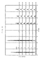
- each sample was set in a manner that an X-ray could be irradiated to the surface having an area of 12 mm ⁇ 3 mm of the processed sample and the X-ray diffraction pattern of each sample was measured by a 2 ⁇ / ⁇ method within a range of 20° to 60°.
- the X-ray diffraction pattern was measured by using an X-ray diffractmetor and a CuK ⁇ -beam as an irradiation source and installing a graphite monochrometer in front of a detector.
- the measurement was carried out after setting the X-ray generation condition to 35 kV-30 mA, a scanning width of 0.02°, a scanning speed of 2°/minute, a diffusion slit of 1°, and a light reception slit of 0.3 mm.
- X-ray diffraction patterns peculiar to the orthorhombic system of perovskite was observed and it can be understood that the crystal system of the sintered bodies was the orthorhombic system.
- X-ray diffraction patterns peculiar to the tetragonal system of perovskite was observed and it can be understood that the crystal system of the sintered bodies was the tetragonal system.
- the Li 3 NbO 4 amount was quantitatively measured.
- the Li 3 NbO 4 amount was calculated from the ratio of the integrated intensity of the diffraction peak of (211) plane of Li 3 NbO 4 in the X-ray diffraction pattern of the sintered body to the total of the integrated intensities of the diffraction peaks of (101) plane and (110) plane of the perovskite.
- the quantitative analysis results are shown in Table 1.
- the Li 3 NbO 4 amounts shown in Table 1 are the weight ratios to 100 parts by mole of the perovskite type oxide.
- the Li 3 NbO 4 amounts of Examples 1 to 9 and Comparative Examples 1 and 2 were within a range of 1.0 to 1.5 parts by weight and in Examples 1 to 9 having desirable compositions, good strain ratios S 4000 were obtained at a firing temperature of 970°C.
- phase transition temperature T OT of each sintered body used for Examples 1 to 9 and Comparative Examples 1 and 2 was measured.
- the phase transition temperature T OT was obtained by measuring the temperature-dependency of a specific dielectric constant ⁇ / ⁇ o by an impedance analyzer. The measurement results are shown in Table 1. As being made clear from the measurement results, as the Ta amount was increased, the phase transition temperature T OT was lowered and if the Ta amount is within a range of 0.1 ⁇ z ⁇ 0.5, the phase transition temperature T OT is within a practically usable temperature range and as a result, the strain ratio S 4000 at room temperature also exceeds 250 ppm.
- the phase transition temperature T OT is not lowered sufficiently, and as a result, it becomes impossible to obtain a good strain ratio S 4000 at room temperature and if the Ta amount exceeds the range, the phase transition temperature T OT is considerably lowered and as a result, it becomes impossible to obtain a good strain ratio S 4000 at room temperature and near the phase transition temperature T OT .
- the piezoelectric constant d 31 (pm/V), the stain ratio S 4000 (ppm), and the sintered density (g/cm 3 ) were measured at room temperature.
- the measurement results are shown in Table 2.
- the sintered density was measured by an Archimedes method.
- the piezoelectric constant d 31 (pm/V), the stain ratios S 4000 (ppm) at room temperature and near the phase transition temperature T OT and the phase transition temperature T OT (°C) were measured.
- the measurement results are shown in Table 3.
- the measurement methods of the piezoelectric constant d 31 and the stain ratios S 4000 were the same as the above-mentioned measurement methods.
- the Li 3 NbO 4 amount was quantitatively measured.
- the quantitative measurement results are shown in Table 3.
- the quantitative measurement method of the Li 3 NbO 4 amount was the same as the above-mentioned quantitative measurement method.
- the phase transition temperature T OT is within a range for practical use and a good strain ratio S 4000 can be obtained.
- the Li 3 NbO 4 amount was within a range of 0.1 to 0.5 parts by weight (Example 14) within a range of 1.0 to 1.5 parts by weight (Examples 15 to 18), and within a range of 2.0 to 3.0 parts by weight (Examples 19 and 20), and good strain ratios S 4000 were obtained by firing at a firing temperature of 970 to 1000°C.
- the Li 3 NbO 4 amount was quantitatively measured.
- the quantitative measurement results are shown in Table 4.
- the quantitative measurement method of the Li 3 NbO 4 amount was the same as the above-mentioned quantitative measurement method.
- Example 21 to 33 and Comparative Examples 3 and 4 as shown in Table 4, the Li 3 NbO 4 amount was within a range of 0.1 to 0.5 parts by weight (Examples 21 to 23), within a range of 1.0 to 1.5 parts by weight (Examples 24 and 26 to 33 and Comparative Examples 3 and 4), and within a range of 2.0 to 3.0 parts by weight (Example 25), and in Examples 21 to 33 having desirable compositions, good strain ratios S 4000 were obtained by firing at a firing temperature of 970 to 1000°C.
- the Li 3 NbO 4 amount was less than 0.1 parts by weight and even if the firing temperature was increased to 1050°C, the sintered density was not saturated and thus it can not be said that even if the firing temperature is increased to 1050°C, sintering can be promoted sufficiently.
- the Li 3 NbO 4 amount was within a range of 0.1 to 0.5 parts by weight (Examples 14 and 34 to 37), within a range of 1.0 to 1.5 parts by weight (Examples 5 and 10 to 13), within a range of 2.0 to 3.0 parts by weight (Examples 20, 38, and 39), and exceeding 3 parts by weight (Examples 40 to 42) and the sintered density was saturated at a firing temperature of 1050°C or lower and thus sintering was sufficiently promoted at a firing temperature of 1050°C or lower.
- Examples 40 to 42 in which the Li 3 NbO 4 amount was more than 3 parts by weight short circuit due to insulation breakdown tended to be caused easily in polarization treatment or operation.
Landscapes
- Chemical & Material Sciences (AREA)
- Engineering & Computer Science (AREA)
- Ceramic Engineering (AREA)
- Organic Chemistry (AREA)
- Materials Engineering (AREA)
- Geology (AREA)
- General Life Sciences & Earth Sciences (AREA)
- Inorganic Chemistry (AREA)
- Environmental & Geological Engineering (AREA)
- Manufacturing & Machinery (AREA)
- Life Sciences & Earth Sciences (AREA)
- Structural Engineering (AREA)
- Compositions Of Oxide Ceramics (AREA)
Applications Claiming Priority (2)
| Application Number | Priority Date | Filing Date | Title |
|---|---|---|---|
| JP2007272082 | 2007-10-19 | ||
| JP2008234585A JP5021595B2 (ja) | 2007-10-19 | 2008-09-12 | 圧電/電歪磁器組成物及び圧電/電歪素子 |
Publications (2)
| Publication Number | Publication Date |
|---|---|
| EP2050726A2 true EP2050726A2 (fr) | 2009-04-22 |
| EP2050726A3 EP2050726A3 (fr) | 2011-10-26 |
Family
ID=40019477
Family Applications (1)
| Application Number | Title | Priority Date | Filing Date |
|---|---|---|---|
| EP08253384A Withdrawn EP2050726A3 (fr) | 2007-10-19 | 2008-10-17 | Composition céramique piézoélectrique/électrostrictif et dispositif piézoélectrique/électrostrictif |
Country Status (2)
| Country | Link |
|---|---|
| US (1) | US8022604B2 (fr) |
| EP (1) | EP2050726A3 (fr) |
Cited By (5)
| Publication number | Priority date | Publication date | Assignee | Title |
|---|---|---|---|---|
| DE102011010346A1 (de) * | 2011-02-04 | 2012-08-09 | H.C. Starck Gmbh | Verfahren zur Herstellung eines phasenreines Mehrstoffsystems, Keramikwerkstoff auf Basis des phasenreinen Mehrstoffsystems und daraus gebildeter Formkörper und Verbundkörper |
| DE102011005940A1 (de) | 2011-03-23 | 2012-09-27 | Carl Zeiss Smt Gmbh | EUV-Spiegelanordnung, optisches System mit EUV-Spiegelanordnung und Verfahren zum Betreiben eines optischen Systems mit EUV-Spiegelanordnung |
| WO2012126954A1 (fr) | 2011-03-23 | 2012-09-27 | Carl Zeiss Smt Gmbh | Dispositif de miroir pour uv extrême, système optique comprenant un dispositif de miroir pour uv extrême, et procédé de mise en œuvre d'un dispositif de miroir pour uv extrême |
| DE102011077234A1 (de) | 2011-06-08 | 2012-12-13 | Carl Zeiss Smt Gmbh | EUV-Spiegelanordnung, optisches System mit EUV-Spiegelanordnung und Verfahren zum Betreiben eines optischen Systems mit EUV-Spiegelanordnung |
| EP2676945A4 (fr) * | 2010-12-24 | 2016-03-30 | Taiyo Yuden Kk | Céramique piézoélectrique, composant de céramique piézoélectrique, et dispositif piézoélectrique dans lequel un composant de céramique piézoélectrique est utilisé |
Families Citing this family (7)
| Publication number | Priority date | Publication date | Assignee | Title |
|---|---|---|---|---|
| US9076968B2 (en) * | 2013-03-14 | 2015-07-07 | Tdk Corporation | Piezoelectric element, piezoelectric actuator, piezoelectric sensor, hard disk drive, and inkjet printer device |
| JP6266987B2 (ja) * | 2013-03-19 | 2018-01-24 | 住友化学株式会社 | 圧電薄膜素子、圧電センサ及び振動発電機 |
| JP6144943B2 (ja) * | 2013-03-29 | 2017-06-07 | 日本碍子株式会社 | 積層体及び圧電/電歪素子 |
| US9343650B2 (en) * | 2013-03-29 | 2016-05-17 | Fuji Chemical Co., Ltd. | Piezoelectric material, piezoelectric element, multilayered piezoelectric element, liquid ejection head, liquid ejection apparatus, ultrasonic motor, optical equipment, vibration apparatus, dust removing apparatus, imaging apparatus, and electronic equipment |
| JP6521241B2 (ja) | 2015-05-28 | 2019-05-29 | セイコーエプソン株式会社 | 圧電素子及び圧電素子応用デバイス |
| US11161125B2 (en) * | 2015-06-22 | 2021-11-02 | Agency For Science, Technology And Research | Fluid jet dispenser using multilayer ceramic actuators |
| US11889767B2 (en) * | 2019-03-14 | 2024-01-30 | Taiyo Yuden Co., Ltd. | Multilayer piezoelectric ceramic and method for manufacturing same, multilayer piezoelectric element, as well as piezoelectric vibration apparatus |
Citations (1)
| Publication number | Priority date | Publication date | Assignee | Title |
|---|---|---|---|---|
| WO2006095716A1 (fr) | 2005-03-08 | 2006-09-14 | Ngk Insulators, Ltd. | Composition de ceramique piezoelectrique et procede pour la produire |
Family Cites Families (23)
| Publication number | Priority date | Publication date | Assignee | Title |
|---|---|---|---|---|
| TW563265B (en) * | 1998-02-18 | 2003-11-21 | Murata Manufacturing Co | Piezoelectric ceramic composition |
| TW429636B (en) * | 1998-02-18 | 2001-04-11 | Murata Manufacturing Co | Piezoelectric ceramic composition |
| KR20010021135A (ko) * | 1999-08-05 | 2001-03-15 | 사토 히로시 | 압전공진자 및 압전공진부 |
| US6514427B2 (en) * | 1999-10-18 | 2003-02-04 | Matsushita Electric Industrial Co., Ltd. | Piezoelectric ceramic composition and piezoelectric element containing the same |
| TWI228728B (en) * | 2001-05-29 | 2005-03-01 | Murata Manufacturing Co | Piezoelectric ceramic composition, piezoelectric ceramic element and method for producing piezoelectric ceramic composition |
| US7309450B2 (en) * | 2001-06-15 | 2007-12-18 | Tdk Corporation | Piezoelectric porcelain and method for preparation thereof |
| DE60323704D1 (de) * | 2002-03-20 | 2008-11-06 | Denso Corp | Piezoelektrische Keramikzusammensetzung, Verfahren zu ihrer Herstellung und piezoelektrische Vorrichtung |
| JP4631246B2 (ja) * | 2002-03-20 | 2011-02-16 | 株式会社豊田中央研究所 | 圧電磁器組成物及びその製造方法並びに圧電素子及び誘電素子 |
| JP4212289B2 (ja) * | 2002-04-04 | 2009-01-21 | Tdk株式会社 | 圧電磁器の製造方法 |
| US7101491B2 (en) * | 2002-07-16 | 2006-09-05 | Denso Corporation | Piezoelectric ceramic composition and method of production of same, piezoelectric element, and dielectric element |
| DE102005042520A1 (de) * | 2004-09-07 | 2006-03-30 | Denso Corp., Kariya | Gestapeltes piezoelektrisches Element und Herstellungsverfahren für dasselbe |
| US7477004B2 (en) * | 2004-09-29 | 2009-01-13 | Ngk Insulators, Ltd. | Piezoelectric/electrostrictive porcelain composition, piezoelectric/electrostrictive article, and piezoelectric/electrostrictive film type element |
| KR100904618B1 (ko) * | 2005-04-28 | 2009-06-25 | 가부시키가이샤 무라타 세이사쿠쇼 | 압전체 자기 조성물, 및 이 압전체 자기 조성물의제조방법, 및 압전 세라믹 전자부품 |
| JP4735840B2 (ja) * | 2005-12-06 | 2011-07-27 | セイコーエプソン株式会社 | 圧電体積層体、表面弾性波素子、薄膜圧電共振子および圧電アクチュエータ |
| US7494601B2 (en) * | 2006-02-28 | 2009-02-24 | The Hong Kong Polytechnic University | Piezoelectric ceramic composition and the method for preparing the same |
| US8124047B2 (en) * | 2006-12-22 | 2012-02-28 | Ngk Insulators, Ltd. | Method for manufacturing (Li, Na, K)(Nb, Ta)O3 type piezoelectric material |
| JP5021452B2 (ja) * | 2007-02-27 | 2012-09-05 | 日本碍子株式会社 | 圧電/電歪磁器組成物および圧電/電歪素子 |
| JP5044437B2 (ja) * | 2007-03-20 | 2012-10-10 | 日本碍子株式会社 | 圧電/電歪磁器焼結体の製造方法 |
| EP2045846B1 (fr) * | 2007-10-03 | 2017-06-07 | NGK Insulators, Ltd. | Composition de céramique piézoélectrique/électrostrictive et dispositif piézoélectrique/électrostrictif |
| JP5391395B2 (ja) * | 2007-10-15 | 2014-01-15 | 日立金属株式会社 | 圧電薄膜付き基板及び圧電素子 |
| JP2010021512A (ja) * | 2008-01-30 | 2010-01-28 | Ngk Insulators Ltd | 圧電/電歪膜型素子及びその製造方法 |
| JP5876974B2 (ja) * | 2008-03-21 | 2016-03-02 | 日本碍子株式会社 | 圧電/電歪磁器組成物の製造方法 |
| JP4987815B2 (ja) * | 2008-07-28 | 2012-07-25 | 日本碍子株式会社 | 圧電/電歪磁器組成物の製造方法 |
-
2008
- 2008-10-15 US US12/251,523 patent/US8022604B2/en not_active Expired - Fee Related
- 2008-10-17 EP EP08253384A patent/EP2050726A3/fr not_active Withdrawn
Patent Citations (1)
| Publication number | Priority date | Publication date | Assignee | Title |
|---|---|---|---|---|
| WO2006095716A1 (fr) | 2005-03-08 | 2006-09-14 | Ngk Insulators, Ltd. | Composition de ceramique piezoelectrique et procede pour la produire |
Non-Patent Citations (1)
| Title |
|---|
| YASUYOSHI SAITO ET AL.: "High Performance Lead-Free Piezoelectric Ceramics in the (K, Na) Nb03-LiTa03 Solid Solution System", FERROELECTRICS (UNITED STATES OF AMERICA, vol. 338, 2006, pages 17 - 32, XP009117499, DOI: doi:10.1080/00150190600732512 |
Cited By (6)
| Publication number | Priority date | Publication date | Assignee | Title |
|---|---|---|---|---|
| EP2676945A4 (fr) * | 2010-12-24 | 2016-03-30 | Taiyo Yuden Kk | Céramique piézoélectrique, composant de céramique piézoélectrique, et dispositif piézoélectrique dans lequel un composant de céramique piézoélectrique est utilisé |
| DE102011010346A1 (de) * | 2011-02-04 | 2012-08-09 | H.C. Starck Gmbh | Verfahren zur Herstellung eines phasenreines Mehrstoffsystems, Keramikwerkstoff auf Basis des phasenreinen Mehrstoffsystems und daraus gebildeter Formkörper und Verbundkörper |
| DE102011010346B4 (de) * | 2011-02-04 | 2014-11-20 | H.C. Starck Gmbh | Verfahren zur Herstellung eines homogenen Mehrstoffsystems, Keramikwerkstoff auf Basis des homogenen Mehrstoffsystems und dessen Verwendung |
| DE102011005940A1 (de) | 2011-03-23 | 2012-09-27 | Carl Zeiss Smt Gmbh | EUV-Spiegelanordnung, optisches System mit EUV-Spiegelanordnung und Verfahren zum Betreiben eines optischen Systems mit EUV-Spiegelanordnung |
| WO2012126954A1 (fr) | 2011-03-23 | 2012-09-27 | Carl Zeiss Smt Gmbh | Dispositif de miroir pour uv extrême, système optique comprenant un dispositif de miroir pour uv extrême, et procédé de mise en œuvre d'un dispositif de miroir pour uv extrême |
| DE102011077234A1 (de) | 2011-06-08 | 2012-12-13 | Carl Zeiss Smt Gmbh | EUV-Spiegelanordnung, optisches System mit EUV-Spiegelanordnung und Verfahren zum Betreiben eines optischen Systems mit EUV-Spiegelanordnung |
Also Published As
| Publication number | Publication date |
|---|---|
| EP2050726A3 (fr) | 2011-10-26 |
| US8022604B2 (en) | 2011-09-20 |
| US20090102325A1 (en) | 2009-04-23 |
Similar Documents
| Publication | Publication Date | Title |
|---|---|---|
| US8022604B2 (en) | (Li, Na, K)(Nb, Ta)O3 type piezoelectric/electrostrictive ceramic composition containing 30-50 mol% Ta and piezoelectric/electrorestrictive device containing the same | |
| EP2045846B1 (fr) | Composition de céramique piézoélectrique/électrostrictive et dispositif piézoélectrique/électrostrictif | |
| JP4800989B2 (ja) | 圧電/電歪材料、圧電/電歪体、及び圧電/電歪素子 | |
| JP4039029B2 (ja) | 圧電セラミックス、圧電素子、および積層型圧電素子 | |
| EP2104152B1 (fr) | Céramique piézoélectrique et élément piézoélectrique l'employant | |
| EP1857425B1 (fr) | Composition de ceramique piezoelectrique et procede pour la produire | |
| EP2187462A2 (fr) | Composition piézoélectrique/électrostrictif céramique, corps piézoélectrique/électrostrictif céramique, procédé de fabrication d'une composition piézoélectrique/électrostrictif céramique, procédé de fabrication d'un corps piézoélectrique/électrostrictif céramique | |
| EP1835554B1 (fr) | Composant céramique piézoélectrique et son procédé de fabrication | |
| JP5021452B2 (ja) | 圧電/電歪磁器組成物および圧電/電歪素子 | |
| US20110012051A1 (en) | Piezoelectric/electrostrictive ceramic composition | |
| US8414791B2 (en) | Piezoelectric/electrostrictive ceramics sintered body | |
| EP2104155B1 (fr) | Procédé de fabrication de composition céramique piézoélectrique/électrostrictive | |
| GB2392550A (en) | Laminated piezoelectric element | |
| EP2131409A1 (fr) | Actionneur piézoélectrique stratifié et tête d'éjection de liquide | |
| JP5129067B2 (ja) | 圧電/電歪磁器組成物及び圧電/電歪素子 | |
| EP2309561A1 (fr) | Corps fritté de céramiques piézoélectriques/électrostrictives | |
| JP5774824B2 (ja) | 圧電/電歪磁器組成物 | |
| JP5021595B2 (ja) | 圧電/電歪磁器組成物及び圧電/電歪素子 | |
| JP5662197B2 (ja) | 圧電/電歪焼結体、及び圧電/電歪素子 |
Legal Events
| Date | Code | Title | Description |
|---|---|---|---|
| PUAI | Public reference made under article 153(3) epc to a published international application that has entered the european phase |
Free format text: ORIGINAL CODE: 0009012 |
|
| AK | Designated contracting states |
Kind code of ref document: A2 Designated state(s): AT BE BG CH CY CZ DE DK EE ES FI FR GB GR HR HU IE IS IT LI LT LU LV MC MT NL NO PL PT RO SE SI SK TR |
|
| AX | Request for extension of the european patent |
Extension state: AL BA MK RS |
|
| PUAL | Search report despatched |
Free format text: ORIGINAL CODE: 0009013 |
|
| AK | Designated contracting states |
Kind code of ref document: A3 Designated state(s): AT BE BG CH CY CZ DE DK EE ES FI FR GB GR HR HU IE IS IT LI LT LU LV MC MT NL NO PL PT RO SE SI SK TR |
|
| AX | Request for extension of the european patent |
Extension state: AL BA MK RS |
|
| RIC1 | Information provided on ipc code assigned before grant |
Ipc: C01G 35/00 20060101ALI20110922BHEP Ipc: C01G 33/00 20060101ALI20110922BHEP Ipc: H01L 41/187 20060101ALI20110922BHEP Ipc: C04B 35/495 20060101AFI20110922BHEP |
|
| 17P | Request for examination filed |
Effective date: 20120308 |
|
| AKX | Designation fees paid |
Designated state(s): AT BE BG CH CY CZ DE DK EE ES FI FR GB GR HR HU IE IS IT LI LT LU LV MC MT NL NO PL PT RO SE SI SK TR |
|
| 17Q | First examination report despatched |
Effective date: 20120627 |
|
| RIC1 | Information provided on ipc code assigned before grant |
Ipc: H01L 41/187 20060101ALI20130423BHEP Ipc: H01L 41/083 20060101ALI20130423BHEP Ipc: C04B 35/495 20060101AFI20130423BHEP Ipc: C01G 35/00 20060101ALI20130423BHEP Ipc: C01G 33/00 20060101ALI20130423BHEP Ipc: C01G 23/00 20060101ALI20130423BHEP |
|
| STAA | Information on the status of an ep patent application or granted ep patent |
Free format text: STATUS: THE APPLICATION IS DEEMED TO BE WITHDRAWN |
|
| 18D | Application deemed to be withdrawn |
Effective date: 20131004 |