EP2050875A2 - Fraiseuse pour chaussées - Google Patents
Fraiseuse pour chaussées Download PDFInfo
- Publication number
- EP2050875A2 EP2050875A2 EP08014883A EP08014883A EP2050875A2 EP 2050875 A2 EP2050875 A2 EP 2050875A2 EP 08014883 A EP08014883 A EP 08014883A EP 08014883 A EP08014883 A EP 08014883A EP 2050875 A2 EP2050875 A2 EP 2050875A2
- Authority
- EP
- European Patent Office
- Prior art keywords
- hold
- milling
- road
- milling machine
- machine according
- Prior art date
- Legal status (The legal status is an assumption and is not a legal conclusion. Google has not performed a legal analysis and makes no representation as to the accuracy of the status listed.)
- Granted
Links
Images


Classifications
-
- E—FIXED CONSTRUCTIONS
- E01—CONSTRUCTION OF ROADS, RAILWAYS, OR BRIDGES
- E01C—CONSTRUCTION OF, OR SURFACES FOR, ROADS, SPORTS GROUNDS, OR THE LIKE; MACHINES OR AUXILIARY TOOLS FOR CONSTRUCTION OR REPAIR
- E01C23/00—Auxiliary devices or arrangements for constructing, repairing, reconditioning, or taking-up road or like surfaces
- E01C23/06—Devices or arrangements for working the finished surface; Devices for repairing or reconditioning the surface of damaged paving; Recycling in place or on the road
- E01C23/08—Devices or arrangements for working the finished surface; Devices for repairing or reconditioning the surface of damaged paving; Recycling in place or on the road for roughening or patterning; for removing the surface down to a predetermined depth high spots or material bonded to the surface, e.g. markings; for maintaining earth roads, clay courts or like surfaces by means of surface working tools, e.g. scarifiers, levelling blades
- E01C23/085—Devices or arrangements for working the finished surface; Devices for repairing or reconditioning the surface of damaged paving; Recycling in place or on the road for roughening or patterning; for removing the surface down to a predetermined depth high spots or material bonded to the surface, e.g. markings; for maintaining earth roads, clay courts or like surfaces by means of surface working tools, e.g. scarifiers, levelling blades using power-driven tools, e.g. vibratory tools
- E01C23/088—Rotary tools, e.g. milling drums
-
- E—FIXED CONSTRUCTIONS
- E02—HYDRAULIC ENGINEERING; FOUNDATIONS; SOIL SHIFTING
- E02F—DREDGING; SOIL-SHIFTING
- E02F3/00—Dredgers; Soil-shifting machines
- E02F3/04—Dredgers; Soil-shifting machines mechanically-driven
- E02F3/18—Dredgers; Soil-shifting machines mechanically-driven with digging wheels turning round an axis, e.g. bucket-type wheels
- E02F3/20—Dredgers; Soil-shifting machines mechanically-driven with digging wheels turning round an axis, e.g. bucket-type wheels with tools that only loosen the material, i.e. mill-type wheels
-
- E—FIXED CONSTRUCTIONS
- E02—HYDRAULIC ENGINEERING; FOUNDATIONS; SOIL SHIFTING
- E02F—DREDGING; SOIL-SHIFTING
- E02F3/00—Dredgers; Soil-shifting machines
- E02F3/04—Dredgers; Soil-shifting machines mechanically-driven
- E02F3/18—Dredgers; Soil-shifting machines mechanically-driven with digging wheels turning round an axis, e.g. bucket-type wheels
- E02F3/22—Component parts
- E02F3/24—Digging wheels; Digging elements of wheels; Drives for wheels
- E02F3/241—Digging wheels; Digging elements of wheels; Drives for wheels digging wheels
Definitions
- the invention relates to a road milling machine according to the preamble of claim 1.
- Road milling machines serve, in particular, to mill off the road surface of damaged roads. Such a milled road then serves as a substructure for a road to be renewed, on which only a new road surface is to be applied.
- Road milling of the type discussed here are usually self-propelled. You can have a caterpillar or a wheel drive.
- the road milling machines are equipped with a milling drum, which is mounted on a transverse to the milling direction horizontal axis of rotation drivable mounted on the frame of the road milling machine.
- the milling drum is largely surrounded by a milling drum box. This has two opposite end faces of the milling drum associated side walls and a part-cylindrical peripheral wall which forms a part-cylindrical box casing.
- the milling drum box seen in the direction of milling, has a so-called hold-down on its front side, which extends a front part of the peripheral wall.
- the hold-down serves to seal the milling drum box in front of the milling point where the milling drum is currently milling away the defective road surface.
- the hold-down is stored for this purpose flying on the Fräswalzenkasten so that it rests on theSSfräsenden defective road surface and automatically adapts to the course of the same.
- the hold-down In known road milling the hold-down is designed as a flat, vertical plate. This creates a large dead space (triangular in cross-section) between the hold-down device and the milling drum. In this dead space collects a large amount of milled road material (milled), which is not removed with the rotating milling drum. This milled material remains in front of the milled surface and must be subsequently removed, which is often possible only manually. In particular, a fairly large amount of material remains at the end of the milling process on the milled surface. Because here a step is present between the milled surface and the still remaining defective road surface, the removal of the front of the milling roller remaining milling material is particularly expensive.
- the invention is an object of the invention to provide a road milling machine, in which only a minimal amount of milled material remains on the milled surface.
- a road milling machine to solve this problem has the features of claim 1. Due to the arcuate design of the hold-down is guided radially around the milling drum. It thus forms no dead space between the milling drum and the hold-down, because follows the course of the cylindrical milling drum by the arcuate design of the hold-down. Consequently, the milled material arising at the milling site is transported along the narrow gap between the milling drum and the hold-down device for suction behind the milling drum. This leaves only a relatively small amount of milled material on the milled surface. Above all, hardly any milled material remains after the completion of the milling process at the level between the milled surface and the remaining road surface.
- the bow-shaped hold-down in such a way that it follows a circular path which runs concentrically around the milling drum.
- the radius of the arcuate holddown is then on the longitudinal center axis of the milling drum.
- an almost equally wide gap is formed between the lateral surface of the milling drum and the bow-shaped holding-down device in the circumferential direction of the milling drum.
- the loose milled material produced during milling of the road surface is taken along in the direction of rotation of the milling drum to the rear of the milling drum due to the rotating milling drum, where the milled material is removed from the milling box.
- the bow-shaped holding-down device is height-adjustable or displaceable on an arcuate path, the center of which is on the axis of rotation of the milling drum is located.
- the hold-down device is displaceable on a circular path parallel to the cylindrical surface of the milling drum, in a geometric sense rotatable or pivotable about a rotation axis corresponding to the axis of rotation of the drum.
- the automatic floating height adjustment of the bow-shaped hold-down takes place by a displaceable mounting of the hold-down between opposite side walls of the milling drum box.
- This type of storage of the bow-shaped hold-down allows an automatic up and down of the same, so that the hold-down can automatically adapt to the course of the milled road surface.
- arcuate slots are likewise provided in the side walls and / or edges of the hold-down device, in particular edge strips of the hold-down device.
- the arcuate slots run parallel to the arcuate wall of the blank holder.
- the arcuate slots lie on a circular path around the center of the milling drum, so that the slots have a circular arc-shaped course with a parallel distance from the cylindrical surface of the milling drum.
- displaceable bearings or bearings are assigned to the oblong holes.
- the bearings ensure that in the oblong holes a virtually backlash-free and tilt-free, slidable mounting of the hold-down against the side walls of the Fräswalzenkastens arises.
- frictional forces between the free transverse edge of the blank holder resting on the road surface to be milled and the road surface can not lead to jamming of the blank holder between the side walls, which causes the automatic up and down movement of the blank holder would prevent.
- the bearings lead to a smooth in all operating conditions of the road milling machine mobility of the hold-down between the side walls by the bearings can slide smoothly along the slots.
- each bearing has at least one rolling element.
- the rolling elements can be formed by bushes that run smoothly with the least possible play in the arcuate slots, in particular roll in the slots.
- the road milling machine has at least one tracking element.
- the Nach211 serves to adjust the height of the hold-down. This ensures that tilting of the hold-down is reliably prevented, since the raising or lowering of the hold-down is made by the Nach1700organ.
- the tracking element is preferably hingedly connected to the hold-down.
- a smooth-running articulated connection, in particular by a rod, between the Nach211organ and the hold-down ensures a low-friction and safe operation of the road milling machine. The fact that the hold-down is raised by the Nach211 from above instead of being directly pushed upwards by the abraded road surface from below, canting be effectively avoided.
- the tracking element is guided on the milling frame and / or on the Fräswalzenkasten in a vertical plane pivoted.
- a guide for example, such as a bolt on the cutter frame or on the Fräswalzenkasten arranged so that the guide can be brought into engagement with the Nach211organ, for example by engaging in a slot of NachGermanorgans.
- Such a guide then allows pivoting of the Nach211organs exclusively in a vertical plane about an axis of rotation, which is aligned perpendicular to the vertical plane.
- the guidance of the Nachriosorgans in a vertical plane can also be designed differently, for example in the form of at least one guide rail.
- the tracking member is preferably brought into contact with the road surface to be scoured.
- the tracking element rests at least partially on the road surface to be scoured.
- the Nach2020organ can ensure an exact tracking of the blank holder in height.
- the tracking member slides along with a slider arranged on the road surface to be scoured off.
- the slider is preferably formed in a circular segment shape with a smooth surface down and aligned curved upward, so that the upwardly bent ends offorcefräsendem pavement point away. As a result, unevenness in the road surface does not lead to a jamming or catching of the slider on these irregularities, but the slider can slide over these irregularities.
- the tracking member is formed substantially triangular and in particular rotatably mounted about a rotation axis.
- the axis of rotation is formed in particular by a bearing on the milling frame of the road milling machine and is preferably arranged at one end or a corner of the Nach211organs.
- the axis of rotation opposite end of the Nach211organs perform a partially substantially vertically aligned movement.
- This axis of rotation opposite the end of the Nach14organs is particularly preferably non-positively connected to the hold-down.
- a vertical movement of this end of the Nachgarorgans also leads to a vertical movement of the blank holder.
- the tracking member is preferably arranged in the milling direction in the area in front of the hold-down. This ensures that the follower organ scans the not yet milled road surface and the height of the holddown can adjust the pavement following.
- the Fig. 1 shows a road milling machine with a cylindrical milling drum 11 for milling defective and / or worn pavements.
- the road milling machine 10 is self-propelled and provided with a corresponding chassis.
- the road milling machine 10 shown has a wheel chassis 12.
- the road milling machine 10 may also have one or more caterpillar drives.
- the road milling machine 10 has a drive for the wheel drive 12 and the milling drum 11.
- the drive drives the milling drum 11 about a horizontal axis of rotation 13.
- the drive may be an internal combustion engine which drives hydraulic pumps, which in turn serve to drive hydraulic motors for the wheeled chassis 12 and the milling drum 11. It is also conceivable that the internal combustion engine drives a generator which generates power for driving electric motors for the wheeled chassis 12 and the milling drum 13.
- the road milling machine 10 has a milling frame 14 to which a milling drum box 15 is coupled.
- the Fräswalzenkasten 15 extends as the axis of rotation 13 of the milling drum 11 transversely to the direction indicated by an arrow milling direction 16 of the road milling machine 10, preferably over the entire or nearly entire width of the road milling machine 10, in particular the Fräsrahmens 14th
- the Fräswalzenkasten 15 is down to its bottom, whereby the distributed distributed on a cylindrical surface 17 of the milling drum 11 arranged chisel 18 can reach theSEAfräsenden defective road surface, closed.
- At least one side wall 20 serves for the rotatable mounting of the milling drum 11 in the milling drum box 15.
- a rear lower part of the box casing 19 is not curved, but straight.
- a lower rear edge of the straight portion of the box shell 19 is associated with a height-adjustable wall element 22. This serves to retain the back of the milling drum 11 by a only partially in the Fig. 1 illustrated conveyor 23gearedtransport Schled road surface, namely the Milling material.
- side plates 24 are still provided, which extend only over a lower half of the milling drum 11 and serve to prevent the lateral exit of milled material from the Fräswalzenkasten 15.
- a hold-down 25 forming a front lower part of the milling drum box 15 is designed.
- This hold-down 25 is formed in the longitudinal direction of the axis of rotation 13 of the milling drum 11 is arcuate.
- the hold-down device 25 extends radially around the milling drum 11, and at a distance from the lateral surface 17 and the tips of the cutting tool 18 of the milling drum 11.
- the hold-down 25 thereby continues the part-circular course of the box shell 19 at the front of the Fräswalzenkastens 15.
- the arcuate hold-down 25 is located on a partial circular path which is concentric with the cylindrical surface 17 of the milling drum 11.
- the center of the arcuate hold-down 25 is thereby on the axis of rotation 13 of the milling drum 11. In this way arises between the cylindrical surface 17 of the milling drum 11 and the arcuate inside of the blank holder 25 in the direction of rotation 26 of the milling drum 11 the same gap space 27.
- the gap 27th is so large that the tips of the cutting tools 18 are all approximately equidistant from the partial arc-shaped curved inside of the blank holder 25, in each rotational position of the milling drum 11 (FIG. Fig. 5 ).
- the milling drum 11 Due to the approximately semi-cylindrical design of the box shell 19 of the same width gap 27 between the hold-down 25 and the cylindrical surface 17 of the milling drum 11 is continued in the area of the box shell 19. In this way, the milling drum 11 is surrounded in the region of the Fräswalzenkastens 15 to the straight wall element 22 in the rear lower portion of the Fräswalzenkastens 15 of a cylinder chamber whose center is located on the axis of rotation 13 of the milling drum 11.
- the box shell 19 and the hold-down 25 are provided with respect to the circumferential direction of the milling drum 11 with such a length that they partially overlap, with an upper part of the blank holder 25 rests on the outside of the box shell 19 or is optionally slightly spaced therefrom.
- an upper transverse edge 28 of the hold-down 25 is above a lower (front) transverse edge 29 of the arcuate or semi-circular box shell 19th
- the hold-down 25 is between the side walls 20 and 21 easily freely up and stored movable. This up and down movement of the blank holder 25 takes place on a part-circular path outside the arcuate, in particular partially cylindrical box shell 19.
- the area with which the hold 25th overlaps the box shell 19, 25 is increased or decreased accordingly when moving up and down of the hold-down.
- a narrow overlap between the hold-down 25 and the box shell 19 is maintained even when completely downwardly moved or heruntergeschwenktem hold-25.
- moving up and down the hold-down 25 this moves quasi about an axis of rotation which is located on the axis of rotation 13 of the milling drum 11, whereby the hold-down 25 moves up and down on a concentric circular path to the box mantle 19.
- the arcuate hold-down 25 is guided during automatic up and down by arcuate slots 30, 31.
- the arcuate course of the slots 30 and 31 is such that their longitudinal center axes lie on a circular path, the center of which is also on the axis of rotation 13 of the milling drum 11.
- the elongated holes 30, 31 as the cylindrical part of the box shell 19 and the hold-down 25 extend on an imaginary concentric circular path to the axis of rotation 13 and the cylindrical surface 17 of the milling drum eleventh
- the slots 30, 31 associated with opposite edges of the blank holder 25.
- the elongated holes 30, 31 are housed in edge strips 32 at opposite arcuate longitudinal edges of the blank holder 25.
- the edge strips 32 project in the manner of collars on the outside of the curved hold-25 outward, so that the pitch circle on which the slots 30, 31 lie, has a slightly larger radius than In the illustrated road milling machine 10, the edge strips 32 are longer, approximately twice as long as the hold-down 25 is formed. As a result, the edge strips 32 overlap the arcuate box jacket 19 over a much greater length than the hold-down 25.
- each edge strip 32 is provided with two successive oblong holes 30 and 31 whose longitudinal center axes lie on a common imaginary concentric circular path about the axis of rotation 13.
- the slots 30 extend approximately over such a peripheral region of the Fräswalzenkastens 15, over which also the hold-down 25 extends.
- the elongated holes 31 located in front of the oblong holes 30 are in the region of the edge strips 32 projecting in the manner of a tongue in relation to the upper transverse edge 28 of the hold-down device.
- the hold-down 25 is mounted visually displaceable by means of the edge strips 32 between opposite side walls 20, 21 of the Fräswalzenkastens 15.
- For storage of the blank holder 25 between the side walls 20 and 21 serve in the illustrated road milling 10 four identically formed bearings 33.
- the bearings 33 are inventively designed so that they hold the hold-down 25 substantially free of play, but easily automatically displaced between the side walls 20, 21.
- each bearing 33 has a bolt 35 fastened to the respective side wall 20, 21, which protrudes inwards relative to the respective side wall 20, 21 and extends through a respective oblong hole 30, 31 in the edge strip 32 lying on the inside adjacent to the side wall 20, 21 extends.
- a freely rotatable sleeve 36 is arranged, whose diameter corresponds approximately to the width of the elongated hole 30 and 31, preferably is slightly thinner, so that the freely rotatable on the bolt 35 mounted sleeve 36 can roll almost free of play in the respective slot 30, 31.
- a thrust washer 37, 38 On both sides of the sleeve 36 is a thrust washer 37, 38 on the bolt 35, which hold the sleeve 36 in the slot 30, 31 and ensure a guide of the bearing 33 on opposite sides of the respective edge strip 32.
- the free lower edge 34 of the blank holder 25 is associated with a solid rod 39.
- the rod 39 which are pointing to her ends of the edge strips 32 are connected.
- the rod 39 and the edge strips 32 form a stable subframe for the guided, frictionless sliding along the edge strips 32 with the hold-down 25 on the inner sides of the side walls 20 and 21.
- the rod 39 serves as abutment of the lower edge 34 of the blank holder 25 on the scoured road surface whereby the hold-down 25 slides along with the rod 39 on the pavement and the course of the same following the hold-down 25 guided by the bearings 33 in the slots 30, 31 moves up and down.
- the second embodiment of the invention is an extension of the first embodiment already described above.
- the road milling machine 10 is formed in principle as described above.
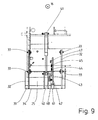
- Fig. 7 to 9 Therefore, only the changes compared to the road milling machine 10 are shown according to the first embodiment.
- the same reference numbers are used for the same parts.
- the hold-down 25 is arranged.
- an additional tracking member 42 is arranged in the milling direction 16 in front of the hold-down 25.
- the tracking member 42 is connected via a control lever 43 to the hold-25.
- the tracking member 42 has a substantially triangular, flat shape, and is rotatably mounted with a pointing away from the hold-down 25 corner on a bearing pin 44 on the milling frame 14 of the road tiller 10 in a vertical plane.
- Another bearing bolt 45 arranged on the milling frame 14 extends through a substantially arcuate one Slot 46 of Nachriosorgans 42.
- a rotation of Nachfuelorgans 42 to the bearing pin 44 is thus possible to the extent that a movement of the bearing pin 45 in the slot 46 is possible.
- the corresponding with the bearing pin 45 slot is used for tilt-free guidance of Nachfuelorgans 42, which is characterized substantially free of play in the vertical plane pivotable.
- the tracking member 42 can be pivoted by an angle of about 30 °.
- the control lever 43 is rotatably mounted on the tracking member 42 in the region of the upper tip parallel to the plane of the Nachtagens 42.
- a bolt 47 is used for this purpose.
- the other end of the control lever 43 is rotatably mounted by means of a bolt 48 in addition to the fork 40 arranged on the hold-down 25 for fastening one end of the hydraulic cylinder 41.
- both the hydraulic cylinder 41 and the tracking element 42 act essentially centrally on the hold-down 25 via the control lever 43.
- the tracking member 42 has a slightly upwardly curved slider 49 in the region of its lower corner. By this slider 49, the tracking member 42 is in contact with the abraded road surface by the slider 49 rests on this. If an increase in the road surface for an upward movement of the slider 49 and thus pivoting the Nach manufacturedorgans 42 provides about the bearing pin 44, the control lever 43 conveys this upward movement of the hold-down 25 so that it moves substantially upwards. With a lowering of the abraded road surface of the slider 49 follows due to the applied gravity of this movement accordingly and the tracking member 42 pivots about the bearing pin 44 down. This movement is also passed from the control lever 43 to the hold-down 25 so that it also moves by gravity down.
- the hold-down 25 moves in the same vertical direction and the same distance as the slider 49, so that the rod 39 of the hold-down 25 during operation of the road tiller 10 at any time rests on the surface of theSSfräsenden road surface. Tilting is reliably prevented by the Nachnaturalorgan 42.
- the hydraulic cylinder 41 can adjust the hold-down 25 and at the same time the tracking member 42 in height.
- a pulling up of the blank holder 25 and the NachStediesorgans 42 for example, for transport purposes possible.
Landscapes
- Engineering & Computer Science (AREA)
- Mechanical Engineering (AREA)
- Mining & Mineral Resources (AREA)
- Civil Engineering (AREA)
- Structural Engineering (AREA)
- General Engineering & Computer Science (AREA)
- Architecture (AREA)
- Road Repair (AREA)
Applications Claiming Priority (2)
| Application Number | Priority Date | Filing Date | Title |
|---|---|---|---|
| DE102007050044 | 2007-10-17 | ||
| DE102008024651A DE102008024651A1 (de) | 2007-10-17 | 2008-05-21 | Straßenfräse |
Publications (3)
| Publication Number | Publication Date |
|---|---|
| EP2050875A2 true EP2050875A2 (fr) | 2009-04-22 |
| EP2050875A3 EP2050875A3 (fr) | 2011-06-22 |
| EP2050875B1 EP2050875B1 (fr) | 2014-09-24 |
Family
ID=40247578
Family Applications (1)
| Application Number | Title | Priority Date | Filing Date |
|---|---|---|---|
| EP08014883.6A Active EP2050875B1 (fr) | 2007-10-17 | 2008-08-22 | Fraiseuse pour chaussées |
Country Status (1)
| Country | Link |
|---|---|
| EP (1) | EP2050875B1 (fr) |
Cited By (15)
| Publication number | Priority date | Publication date | Assignee | Title |
|---|---|---|---|---|
| CN102493325A (zh) * | 2011-12-17 | 2012-06-13 | 于健 | 一种路面铣刨机 |
| US8556536B2 (en) | 2009-01-02 | 2013-10-15 | Heatwurx, Inc. | Asphalt repair system and method |
| US8562247B2 (en) | 2009-01-02 | 2013-10-22 | Heatwurx, Inc. | Asphalt repair system and method |
| US20130341997A1 (en) * | 2012-06-25 | 2013-12-26 | Wirtgen Gmbh | Road Milling Machine |
| USD700633S1 (en) | 2013-07-26 | 2014-03-04 | Heatwurx, Inc. | Asphalt repair device |
| EP2708650A2 (fr) | 2012-06-25 | 2014-03-19 | Wirtgen GmbH | Engin de construction automoteur |
| US8801325B1 (en) | 2013-02-26 | 2014-08-12 | Heatwurx, Inc. | System and method for controlling an asphalt repair apparatus |
| US9016798B2 (en) | 2012-08-06 | 2015-04-28 | Wirtgen Gmbh | Self-propelled construction machine |
| US9995009B2 (en) | 2014-12-04 | 2018-06-12 | Wirtgen Gmbh | Self-propelled construction machine and method for operating a self-propelled construction machine |
| US10113275B2 (en) | 2015-11-12 | 2018-10-30 | Wirtgen Gmbh | Self-propelled ground milling machine and method for working on a traffic surface |
| CN110499699A (zh) * | 2019-08-14 | 2019-11-26 | 山东朝帆机械有限公司 | 一种具有吸尘功能的铣刨机 |
| CN113818312A (zh) * | 2020-06-19 | 2021-12-21 | 宝马格有限公司 | 用于压实基面覆盖物层的地面压实装置、沥青压路机和用于运行地面压实装置的方法 |
| EP4060118A1 (fr) * | 2021-03-15 | 2022-09-21 | Wirtgen GmbH | Machine autonome à construire ou à extraire |
| CN116876312A (zh) * | 2023-09-06 | 2023-10-13 | 河南中鼎智建科技有限公司 | 一种桥梁路面高效修整机 |
| EP4324985A1 (fr) * | 2022-08-18 | 2024-02-21 | Wirtgen GmbH | Accessoire de fraisage avec couvercle réglable |
Families Citing this family (2)
| Publication number | Priority date | Publication date | Assignee | Title |
|---|---|---|---|---|
| US9416499B2 (en) | 2009-12-31 | 2016-08-16 | Heatwurx, Inc. | System and method for sensing and managing pothole location and pothole characteristics |
| CN104929027B (zh) * | 2015-07-24 | 2017-03-22 | 北京时代浩鼎科技股份有限公司 | 一种降尘的道路施工装置 |
Citations (2)
| Publication number | Priority date | Publication date | Assignee | Title |
|---|---|---|---|---|
| DE2160403A1 (de) | 1971-12-06 | 1973-07-12 | Reinhard Wirtgen | Maschine zum abfraesen von strassendecken |
| EP1522634A2 (fr) | 2003-10-10 | 2005-04-13 | WIRTGEN GmbH | Dispositif de fraisage de route à chargement par l'arrière avec dispositif d'étanchéité réglable en hauteur |
Family Cites Families (2)
| Publication number | Priority date | Publication date | Assignee | Title |
|---|---|---|---|---|
| US4221434A (en) * | 1978-03-23 | 1980-09-09 | Cmi Corporation | Roadway breaker plate for a planar apparatus |
| DE4324234A1 (de) * | 1993-07-20 | 1995-01-26 | Willi Jacobs | Fräsbrecher |
-
2008
- 2008-08-22 EP EP08014883.6A patent/EP2050875B1/fr active Active
Patent Citations (2)
| Publication number | Priority date | Publication date | Assignee | Title |
|---|---|---|---|---|
| DE2160403A1 (de) | 1971-12-06 | 1973-07-12 | Reinhard Wirtgen | Maschine zum abfraesen von strassendecken |
| EP1522634A2 (fr) | 2003-10-10 | 2005-04-13 | WIRTGEN GmbH | Dispositif de fraisage de route à chargement par l'arrière avec dispositif d'étanchéité réglable en hauteur |
Cited By (28)
| Publication number | Priority date | Publication date | Assignee | Title |
|---|---|---|---|---|
| US8714871B2 (en) | 2009-01-02 | 2014-05-06 | Heatwurx, Inc. | Asphalt repair system and method |
| US8556536B2 (en) | 2009-01-02 | 2013-10-15 | Heatwurx, Inc. | Asphalt repair system and method |
| US8562247B2 (en) | 2009-01-02 | 2013-10-22 | Heatwurx, Inc. | Asphalt repair system and method |
| CN102493325A (zh) * | 2011-12-17 | 2012-06-13 | 于健 | 一种路面铣刨机 |
| US9714488B2 (en) | 2012-06-25 | 2017-07-25 | Wirtgen Gmbh | Road milling machine |
| EP2708650A2 (fr) | 2012-06-25 | 2014-03-19 | Wirtgen GmbH | Engin de construction automoteur |
| DE102012012397A1 (de) | 2012-06-25 | 2014-04-24 | Wirtgen Gmbh | Selbstfahrende Baumaschine |
| US8939515B2 (en) | 2012-06-25 | 2015-01-27 | Wirtgen Gmbh | Road milling machine |
| US8944517B2 (en) | 2012-06-25 | 2015-02-03 | Wirtgen Gmbh | Self-propelled construction machine |
| EP2708650A3 (fr) * | 2012-06-25 | 2015-11-18 | Wirtgen GmbH | Engin de construction automoteur |
| US9422677B2 (en) | 2012-06-25 | 2016-08-23 | Wirtgen Gmbh | Self-propelled construction machine |
| US20130341997A1 (en) * | 2012-06-25 | 2013-12-26 | Wirtgen Gmbh | Road Milling Machine |
| US9016798B2 (en) | 2012-08-06 | 2015-04-28 | Wirtgen Gmbh | Self-propelled construction machine |
| US8801325B1 (en) | 2013-02-26 | 2014-08-12 | Heatwurx, Inc. | System and method for controlling an asphalt repair apparatus |
| USD700633S1 (en) | 2013-07-26 | 2014-03-04 | Heatwurx, Inc. | Asphalt repair device |
| US9995009B2 (en) | 2014-12-04 | 2018-06-12 | Wirtgen Gmbh | Self-propelled construction machine and method for operating a self-propelled construction machine |
| US10626563B2 (en) | 2014-12-04 | 2020-04-21 | Wirtgen Gmbh | Self-propelled construction machine and method for operating a self-propelled construction machine |
| US10113275B2 (en) | 2015-11-12 | 2018-10-30 | Wirtgen Gmbh | Self-propelled ground milling machine and method for working on a traffic surface |
| US10655285B2 (en) | 2015-11-12 | 2020-05-19 | Wirtgen Gmbh | Self-propelled ground milling machine and method for working on a traffic surface |
| US11286627B2 (en) | 2015-11-12 | 2022-03-29 | Wirtgen Gmbh | Self-propelled ground milling machine and method for working on a traffic surface |
| CN110499699A (zh) * | 2019-08-14 | 2019-11-26 | 山东朝帆机械有限公司 | 一种具有吸尘功能的铣刨机 |
| CN113818312A (zh) * | 2020-06-19 | 2021-12-21 | 宝马格有限公司 | 用于压实基面覆盖物层的地面压实装置、沥青压路机和用于运行地面压实装置的方法 |
| EP4060118A1 (fr) * | 2021-03-15 | 2022-09-21 | Wirtgen GmbH | Machine autonome à construire ou à extraire |
| EP4324985A1 (fr) * | 2022-08-18 | 2024-02-21 | Wirtgen GmbH | Accessoire de fraisage avec couvercle réglable |
| US12071733B2 (en) | 2022-08-18 | 2024-08-27 | Wirtgen Gmbh | Milling attachment with adjustable cover |
| EP4455413A3 (fr) * | 2022-08-18 | 2025-01-15 | Wirtgen GmbH | Accessoire de fraisage avec couvercle réglable |
| CN116876312A (zh) * | 2023-09-06 | 2023-10-13 | 河南中鼎智建科技有限公司 | 一种桥梁路面高效修整机 |
| CN116876312B (zh) * | 2023-09-06 | 2023-12-05 | 河南中鼎智建科技有限公司 | 一种桥梁路面高效修整机 |
Also Published As
| Publication number | Publication date |
|---|---|
| EP2050875A3 (fr) | 2011-06-22 |
| EP2050875B1 (fr) | 2014-09-24 |
Similar Documents
| Publication | Publication Date | Title |
|---|---|---|
| EP2050875B1 (fr) | Fraiseuse pour chaussées | |
| EP2378002B1 (fr) | Dispositif de pelousage pour établir une fente s'étendant verticalement dans le sol | |
| EP2374937B1 (fr) | Engin de traitement d'une surface de voie de circulation | |
| DE102008024651A1 (de) | Straßenfräse | |
| DE3026486C2 (de) | Vorrichtung für die Schleppaufhängung eines Schaufelblattes zur Förderung eines Gutes, insbes. bei einem Tellertrockner | |
| DE2725233C2 (de) | Bodenbearbeitungsmaschine | |
| DE2932695A1 (de) | Bodenbearbeitungsmaschine | |
| DE102011118791B4 (de) | Förderband zur Verwendung in einer Fräsvorrichtung und Fräsvorrichtung mit einem solchen Förderband | |
| DE2329850A1 (de) | Vorrichtung zum wenden und stapeln von gittermatten | |
| DE7317990U (de) | Kreiselegge | |
| DE6937288U (de) | Lineares umlaufrollenlager. | |
| DE2949082A1 (de) | Einrichtung zum anbringen eines schuerfwerkzeuges am vorderende eines fahrzeuges | |
| EP4108831B1 (fr) | Procédé de commande d'un engin de fraisage de chaussée et engin de fraisage de chaussée | |
| DE4115828C2 (de) | Mikrowellenofen | |
| DE2508211C2 (fr) | ||
| CH630225A5 (de) | Kreiselegge. | |
| DE1634844C3 (de) | Schürfkübelfahrzeug mit Kratzerkettenförderer | |
| DE3015084A1 (de) | Aushubgeraet | |
| DE2924732A1 (de) | Bodenbearbeitungsmaschine | |
| EP0477166B1 (fr) | Machine pour enlever les renflements de la partie inférieure du trone d'un arbre | |
| DE69808417T2 (de) | Gerät zum versetzen von auf dem boden liegendem erntegut, insbesondere kreiselheuwender und montageeinheit dafür | |
| DE3246001C2 (fr) | ||
| DE29612192U1 (de) | Bördelvorrichtung | |
| EP4686788A1 (fr) | Fraise pour rideau souterrain avec caisson d'aspiration | |
| DE102022131341A1 (de) | Schlitzwandfräse |
Legal Events
| Date | Code | Title | Description |
|---|---|---|---|
| PUAI | Public reference made under article 153(3) epc to a published international application that has entered the european phase |
Free format text: ORIGINAL CODE: 0009012 |
|
| AK | Designated contracting states |
Kind code of ref document: A2 Designated state(s): AT BE BG CH CY CZ DE DK EE ES FI FR GB GR HR HU IE IS IT LI LT LU LV MC MT NL NO PL PT RO SE SI SK TR |
|
| AX | Request for extension of the european patent |
Extension state: AL BA MK RS |
|
| PUAL | Search report despatched |
Free format text: ORIGINAL CODE: 0009013 |
|
| AK | Designated contracting states |
Kind code of ref document: A3 Designated state(s): AT BE BG CH CY CZ DE DK EE ES FI FR GB GR HR HU IE IS IT LI LT LU LV MC MT NL NO PL PT RO SE SI SK TR |
|
| AX | Request for extension of the european patent |
Extension state: AL BA MK RS |
|
| 17P | Request for examination filed |
Effective date: 20111220 |
|
| AKX | Designation fees paid |
Designated state(s): AT BE BG CH CY CZ DE DK EE ES FI FR GB GR HR HU IE IS IT LI LT LU LV MC MT NL NO PL PT RO SE SI SK TR |
|
| GRAP | Despatch of communication of intention to grant a patent |
Free format text: ORIGINAL CODE: EPIDOSNIGR1 |
|
| RIC1 | Information provided on ipc code assigned before grant |
Ipc: E02F 3/20 20060101ALI20140311BHEP Ipc: E02F 3/24 20060101ALI20140311BHEP Ipc: E01C 23/088 20060101AFI20140311BHEP |
|
| INTG | Intention to grant announced |
Effective date: 20140411 |
|
| GRAS | Grant fee paid |
Free format text: ORIGINAL CODE: EPIDOSNIGR3 |
|
| GRAA | (expected) grant |
Free format text: ORIGINAL CODE: 0009210 |
|
| AK | Designated contracting states |
Kind code of ref document: B1 Designated state(s): AT BE BG CH CY CZ DE DK EE ES FI FR GB GR HR HU IE IS IT LI LT LU LV MC MT NL NO PL PT RO SE SI SK TR |
|
| REG | Reference to a national code |
Ref country code: GB Ref legal event code: FG4D Free format text: NOT ENGLISH |
|
| REG | Reference to a national code |
Ref country code: CH Ref legal event code: EP |
|
| REG | Reference to a national code |
Ref country code: AT Ref legal event code: REF Ref document number: 688718 Country of ref document: AT Kind code of ref document: T Effective date: 20141015 |
|
| REG | Reference to a national code |
Ref country code: IE Ref legal event code: FG4D Free format text: LANGUAGE OF EP DOCUMENT: GERMAN |
|
| REG | Reference to a national code |
Ref country code: DE Ref legal event code: R096 Ref document number: 502008012238 Country of ref document: DE Effective date: 20141030 |
|
| PG25 | Lapsed in a contracting state [announced via postgrant information from national office to epo] |
Ref country code: NO Free format text: LAPSE BECAUSE OF FAILURE TO SUBMIT A TRANSLATION OF THE DESCRIPTION OR TO PAY THE FEE WITHIN THE PRESCRIBED TIME-LIMIT Effective date: 20141224 Ref country code: LT Free format text: LAPSE BECAUSE OF FAILURE TO SUBMIT A TRANSLATION OF THE DESCRIPTION OR TO PAY THE FEE WITHIN THE PRESCRIBED TIME-LIMIT Effective date: 20140924 Ref country code: GR Free format text: LAPSE BECAUSE OF FAILURE TO SUBMIT A TRANSLATION OF THE DESCRIPTION OR TO PAY THE FEE WITHIN THE PRESCRIBED TIME-LIMIT Effective date: 20141225 Ref country code: SE Free format text: LAPSE BECAUSE OF FAILURE TO SUBMIT A TRANSLATION OF THE DESCRIPTION OR TO PAY THE FEE WITHIN THE PRESCRIBED TIME-LIMIT Effective date: 20140924 Ref country code: FI Free format text: LAPSE BECAUSE OF FAILURE TO SUBMIT A TRANSLATION OF THE DESCRIPTION OR TO PAY THE FEE WITHIN THE PRESCRIBED TIME-LIMIT Effective date: 20140924 |
|
| REG | Reference to a national code |
Ref country code: LT Ref legal event code: MG4D Ref country code: NL Ref legal event code: VDEP Effective date: 20140924 |
|
| PG25 | Lapsed in a contracting state [announced via postgrant information from national office to epo] |
Ref country code: LV Free format text: LAPSE BECAUSE OF FAILURE TO SUBMIT A TRANSLATION OF THE DESCRIPTION OR TO PAY THE FEE WITHIN THE PRESCRIBED TIME-LIMIT Effective date: 20140924 Ref country code: CY Free format text: LAPSE BECAUSE OF FAILURE TO SUBMIT A TRANSLATION OF THE DESCRIPTION OR TO PAY THE FEE WITHIN THE PRESCRIBED TIME-LIMIT Effective date: 20140924 Ref country code: HR Free format text: LAPSE BECAUSE OF FAILURE TO SUBMIT A TRANSLATION OF THE DESCRIPTION OR TO PAY THE FEE WITHIN THE PRESCRIBED TIME-LIMIT Effective date: 20140924 |
|
| PG25 | Lapsed in a contracting state [announced via postgrant information from national office to epo] |
Ref country code: NL Free format text: LAPSE BECAUSE OF FAILURE TO SUBMIT A TRANSLATION OF THE DESCRIPTION OR TO PAY THE FEE WITHIN THE PRESCRIBED TIME-LIMIT Effective date: 20140924 |
|
| PG25 | Lapsed in a contracting state [announced via postgrant information from national office to epo] |
Ref country code: EE Free format text: LAPSE BECAUSE OF FAILURE TO SUBMIT A TRANSLATION OF THE DESCRIPTION OR TO PAY THE FEE WITHIN THE PRESCRIBED TIME-LIMIT Effective date: 20140924 Ref country code: PT Free format text: LAPSE BECAUSE OF FAILURE TO SUBMIT A TRANSLATION OF THE DESCRIPTION OR TO PAY THE FEE WITHIN THE PRESCRIBED TIME-LIMIT Effective date: 20150126 Ref country code: RO Free format text: LAPSE BECAUSE OF FAILURE TO SUBMIT A TRANSLATION OF THE DESCRIPTION OR TO PAY THE FEE WITHIN THE PRESCRIBED TIME-LIMIT Effective date: 20140924 Ref country code: ES Free format text: LAPSE BECAUSE OF FAILURE TO SUBMIT A TRANSLATION OF THE DESCRIPTION OR TO PAY THE FEE WITHIN THE PRESCRIBED TIME-LIMIT Effective date: 20140924 Ref country code: SK Free format text: LAPSE BECAUSE OF FAILURE TO SUBMIT A TRANSLATION OF THE DESCRIPTION OR TO PAY THE FEE WITHIN THE PRESCRIBED TIME-LIMIT Effective date: 20140924 Ref country code: IS Free format text: LAPSE BECAUSE OF FAILURE TO SUBMIT A TRANSLATION OF THE DESCRIPTION OR TO PAY THE FEE WITHIN THE PRESCRIBED TIME-LIMIT Effective date: 20150124 Ref country code: CZ Free format text: LAPSE BECAUSE OF FAILURE TO SUBMIT A TRANSLATION OF THE DESCRIPTION OR TO PAY THE FEE WITHIN THE PRESCRIBED TIME-LIMIT Effective date: 20140924 |
|
| PG25 | Lapsed in a contracting state [announced via postgrant information from national office to epo] |
Ref country code: PL Free format text: LAPSE BECAUSE OF FAILURE TO SUBMIT A TRANSLATION OF THE DESCRIPTION OR TO PAY THE FEE WITHIN THE PRESCRIBED TIME-LIMIT Effective date: 20140924 |
|
| REG | Reference to a national code |
Ref country code: DE Ref legal event code: R097 Ref document number: 502008012238 Country of ref document: DE |
|
| PG25 | Lapsed in a contracting state [announced via postgrant information from national office to epo] |
Ref country code: DK Free format text: LAPSE BECAUSE OF FAILURE TO SUBMIT A TRANSLATION OF THE DESCRIPTION OR TO PAY THE FEE WITHIN THE PRESCRIBED TIME-LIMIT Effective date: 20140924 |
|
| PLBE | No opposition filed within time limit |
Free format text: ORIGINAL CODE: 0009261 |
|
| STAA | Information on the status of an ep patent application or granted ep patent |
Free format text: STATUS: NO OPPOSITION FILED WITHIN TIME LIMIT |
|
| PG25 | Lapsed in a contracting state [announced via postgrant information from national office to epo] |
Ref country code: IT Free format text: LAPSE BECAUSE OF FAILURE TO SUBMIT A TRANSLATION OF THE DESCRIPTION OR TO PAY THE FEE WITHIN THE PRESCRIBED TIME-LIMIT Effective date: 20140924 |
|
| 26N | No opposition filed |
Effective date: 20150625 |
|
| PG25 | Lapsed in a contracting state [announced via postgrant information from national office to epo] |
Ref country code: SI Free format text: LAPSE BECAUSE OF FAILURE TO SUBMIT A TRANSLATION OF THE DESCRIPTION OR TO PAY THE FEE WITHIN THE PRESCRIBED TIME-LIMIT Effective date: 20140924 |
|
| PG25 | Lapsed in a contracting state [announced via postgrant information from national office to epo] |
Ref country code: LU Free format text: LAPSE BECAUSE OF FAILURE TO SUBMIT A TRANSLATION OF THE DESCRIPTION OR TO PAY THE FEE WITHIN THE PRESCRIBED TIME-LIMIT Effective date: 20150822 Ref country code: MC Free format text: LAPSE BECAUSE OF FAILURE TO SUBMIT A TRANSLATION OF THE DESCRIPTION OR TO PAY THE FEE WITHIN THE PRESCRIBED TIME-LIMIT Effective date: 20140924 |
|
| REG | Reference to a national code |
Ref country code: CH Ref legal event code: PL |
|
| GBPC | Gb: european patent ceased through non-payment of renewal fee |
Effective date: 20150822 |
|
| PG25 | Lapsed in a contracting state [announced via postgrant information from national office to epo] |
Ref country code: CH Free format text: LAPSE BECAUSE OF NON-PAYMENT OF DUE FEES Effective date: 20150831 Ref country code: LI Free format text: LAPSE BECAUSE OF NON-PAYMENT OF DUE FEES Effective date: 20150831 |
|
| REG | Reference to a national code |
Ref country code: IE Ref legal event code: MM4A |
|
| REG | Reference to a national code |
Ref country code: FR Ref legal event code: ST Effective date: 20160429 |
|
| PG25 | Lapsed in a contracting state [announced via postgrant information from national office to epo] |
Ref country code: GB Free format text: LAPSE BECAUSE OF NON-PAYMENT OF DUE FEES Effective date: 20150822 Ref country code: IE Free format text: LAPSE BECAUSE OF NON-PAYMENT OF DUE FEES Effective date: 20150822 |
|
| PG25 | Lapsed in a contracting state [announced via postgrant information from national office to epo] |
Ref country code: FR Free format text: LAPSE BECAUSE OF NON-PAYMENT OF DUE FEES Effective date: 20150831 |
|
| REG | Reference to a national code |
Ref country code: AT Ref legal event code: MM01 Ref document number: 688718 Country of ref document: AT Kind code of ref document: T Effective date: 20150822 |
|
| PG25 | Lapsed in a contracting state [announced via postgrant information from national office to epo] |
Ref country code: AT Free format text: LAPSE BECAUSE OF NON-PAYMENT OF DUE FEES Effective date: 20150822 |
|
| PG25 | Lapsed in a contracting state [announced via postgrant information from national office to epo] |
Ref country code: MT Free format text: LAPSE BECAUSE OF FAILURE TO SUBMIT A TRANSLATION OF THE DESCRIPTION OR TO PAY THE FEE WITHIN THE PRESCRIBED TIME-LIMIT Effective date: 20140924 |
|
| PG25 | Lapsed in a contracting state [announced via postgrant information from national office to epo] |
Ref country code: BG Free format text: LAPSE BECAUSE OF FAILURE TO SUBMIT A TRANSLATION OF THE DESCRIPTION OR TO PAY THE FEE WITHIN THE PRESCRIBED TIME-LIMIT Effective date: 20140924 Ref country code: HU Free format text: LAPSE BECAUSE OF FAILURE TO SUBMIT A TRANSLATION OF THE DESCRIPTION OR TO PAY THE FEE WITHIN THE PRESCRIBED TIME-LIMIT; INVALID AB INITIO Effective date: 20080822 |
|
| PG25 | Lapsed in a contracting state [announced via postgrant information from national office to epo] |
Ref country code: BE Free format text: LAPSE BECAUSE OF NON-PAYMENT OF DUE FEES Effective date: 20150831 |
|
| PG25 | Lapsed in a contracting state [announced via postgrant information from national office to epo] |
Ref country code: TR Free format text: LAPSE BECAUSE OF FAILURE TO SUBMIT A TRANSLATION OF THE DESCRIPTION OR TO PAY THE FEE WITHIN THE PRESCRIBED TIME-LIMIT Effective date: 20140924 |
|
| P01 | Opt-out of the competence of the unified patent court (upc) registered |
Effective date: 20230529 |
|
| PGFP | Annual fee paid to national office [announced via postgrant information from national office to epo] |
Ref country code: DE Payment date: 20250819 Year of fee payment: 18 |