EP2050908A1 - Mécanisme integré - Google Patents
Mécanisme integré Download PDFInfo
- Publication number
- EP2050908A1 EP2050908A1 EP07020237A EP07020237A EP2050908A1 EP 2050908 A1 EP2050908 A1 EP 2050908A1 EP 07020237 A EP07020237 A EP 07020237A EP 07020237 A EP07020237 A EP 07020237A EP 2050908 A1 EP2050908 A1 EP 2050908A1
- Authority
- EP
- European Patent Office
- Prior art keywords
- housing
- mounting mechanism
- mechanism according
- lever
- damping
- Prior art date
- Legal status (The legal status is an assumption and is not a legal conclusion. Google has not performed a legal analysis and makes no representation as to the accuracy of the status listed.)
- Withdrawn
Links
- 238000013016 damping Methods 0.000 claims abstract description 41
- 238000009434 installation Methods 0.000 claims abstract description 13
- 210000000078 claw Anatomy 0.000 claims description 30
- 230000006835 compression Effects 0.000 claims description 7
- 238000007906 compression Methods 0.000 claims description 7
- 239000013536 elastomeric material Substances 0.000 claims description 2
- 239000000463 material Substances 0.000 claims description 2
- 230000000712 assembly Effects 0.000 claims 1
- 238000000429 assembly Methods 0.000 claims 1
- 210000002414 leg Anatomy 0.000 description 5
- 210000003127 knee Anatomy 0.000 description 2
- FGRBYDKOBBBPOI-UHFFFAOYSA-N 10,10-dioxo-2-[4-(N-phenylanilino)phenyl]thioxanthen-9-one Chemical compound O=C1c2ccccc2S(=O)(=O)c2ccc(cc12)-c1ccc(cc1)N(c1ccccc1)c1ccccc1 FGRBYDKOBBBPOI-UHFFFAOYSA-N 0.000 description 1
- 208000027418 Wounds and injury Diseases 0.000 description 1
- 230000002238 attenuated effect Effects 0.000 description 1
- 230000006378 damage Effects 0.000 description 1
- 230000000694 effects Effects 0.000 description 1
- 239000003112 inhibitor Substances 0.000 description 1
- 208000014674 injury Diseases 0.000 description 1
- 238000000034 method Methods 0.000 description 1
Images




Classifications
-
- E—FIXED CONSTRUCTIONS
- E05—LOCKS; KEYS; WINDOW OR DOOR FITTINGS; SAFES
- E05C—BOLTS OR FASTENING DEVICES FOR WINGS, SPECIALLY FOR DOORS OR WINDOWS
- E05C19/00—Other devices specially designed for securing wings, e.g. with suction cups
- E05C19/02—Automatic catches, i.e. released by pull or pressure on the wing
- E05C19/024—Automatic catches, i.e. released by pull or pressure on the wing with a bifurcated latch
-
- E—FIXED CONSTRUCTIONS
- E05—LOCKS; KEYS; WINDOW OR DOOR FITTINGS; SAFES
- E05F—DEVICES FOR MOVING WINGS INTO OPEN OR CLOSED POSITION; CHECKS FOR WINGS; WING FITTINGS NOT OTHERWISE PROVIDED FOR, CONCERNED WITH THE FUNCTIONING OF THE WING
- E05F5/00—Braking devices, e.g. checks; Stops; Buffers
- E05F5/02—Braking devices, e.g. checks; Stops; Buffers specially for preventing the slamming of swinging wings during final closing movement, e.g. jamb stops
- E05F5/027—Braking devices, e.g. checks; Stops; Buffers specially for preventing the slamming of swinging wings during final closing movement, e.g. jamb stops with closing action
-
- E—FIXED CONSTRUCTIONS
- E05—LOCKS; KEYS; WINDOW OR DOOR FITTINGS; SAFES
- E05F—DEVICES FOR MOVING WINGS INTO OPEN OR CLOSED POSITION; CHECKS FOR WINGS; WING FITTINGS NOT OTHERWISE PROVIDED FOR, CONCERNED WITH THE FUNCTIONING OF THE WING
- E05F5/00—Braking devices, e.g. checks; Stops; Buffers
- E05F5/06—Buffers or stops limiting opening of swinging wings, e.g. floor or wall stops
- E05F5/10—Buffers or stops limiting opening of swinging wings, e.g. floor or wall stops with piston brakes
-
- E—FIXED CONSTRUCTIONS
- E05—LOCKS; KEYS; WINDOW OR DOOR FITTINGS; SAFES
- E05F—DEVICES FOR MOVING WINGS INTO OPEN OR CLOSED POSITION; CHECKS FOR WINGS; WING FITTINGS NOT OTHERWISE PROVIDED FOR, CONCERNED WITH THE FUNCTIONING OF THE WING
- E05F3/00—Closers or openers with braking devices, e.g. checks; Construction of pneumatic or liquid braking devices
- E05F3/22—Additional arrangements for closers, e.g. for holding the wing in opened or other position
- E05F2003/228—Arrangements where the end of the closer arm is sliding in a track
-
- E—FIXED CONSTRUCTIONS
- E05—LOCKS; KEYS; WINDOW OR DOOR FITTINGS; SAFES
- E05Y—INDEXING SCHEME ASSOCIATED WITH SUBCLASSES E05D AND E05F, RELATING TO CONSTRUCTION ELEMENTS, ELECTRIC CONTROL, POWER SUPPLY, POWER SIGNAL OR TRANSMISSION, USER INTERFACES, MOUNTING OR COUPLING, DETAILS, ACCESSORIES, AUXILIARY OPERATIONS NOT OTHERWISE PROVIDED FOR, APPLICATION THEREOF
- E05Y2201/00—Constructional elements; Accessories therefor
- E05Y2201/20—Brakes; Disengaging means; Holders; Stops; Valves; Accessories therefor
- E05Y2201/21—Brakes
-
- E—FIXED CONSTRUCTIONS
- E05—LOCKS; KEYS; WINDOW OR DOOR FITTINGS; SAFES
- E05Y—INDEXING SCHEME ASSOCIATED WITH SUBCLASSES E05D AND E05F, RELATING TO CONSTRUCTION ELEMENTS, ELECTRIC CONTROL, POWER SUPPLY, POWER SIGNAL OR TRANSMISSION, USER INTERFACES, MOUNTING OR COUPLING, DETAILS, ACCESSORIES, AUXILIARY OPERATIONS NOT OTHERWISE PROVIDED FOR, APPLICATION THEREOF
- E05Y2201/00—Constructional elements; Accessories therefor
- E05Y2201/20—Brakes; Disengaging means; Holders; Stops; Valves; Accessories therefor
- E05Y2201/252—Type of friction
- E05Y2201/254—Fluid or viscous friction
- E05Y2201/256—Fluid or viscous friction with pistons or vanes
-
- E—FIXED CONSTRUCTIONS
- E05—LOCKS; KEYS; WINDOW OR DOOR FITTINGS; SAFES
- E05Y—INDEXING SCHEME ASSOCIATED WITH SUBCLASSES E05D AND E05F, RELATING TO CONSTRUCTION ELEMENTS, ELECTRIC CONTROL, POWER SUPPLY, POWER SIGNAL OR TRANSMISSION, USER INTERFACES, MOUNTING OR COUPLING, DETAILS, ACCESSORIES, AUXILIARY OPERATIONS NOT OTHERWISE PROVIDED FOR, APPLICATION THEREOF
- E05Y2201/00—Constructional elements; Accessories therefor
- E05Y2201/20—Brakes; Disengaging means; Holders; Stops; Valves; Accessories therefor
- E05Y2201/262—Type of motion, e.g. braking
- E05Y2201/264—Type of motion, e.g. braking linear
-
- E—FIXED CONSTRUCTIONS
- E05—LOCKS; KEYS; WINDOW OR DOOR FITTINGS; SAFES
- E05Y—INDEXING SCHEME ASSOCIATED WITH SUBCLASSES E05D AND E05F, RELATING TO CONSTRUCTION ELEMENTS, ELECTRIC CONTROL, POWER SUPPLY, POWER SIGNAL OR TRANSMISSION, USER INTERFACES, MOUNTING OR COUPLING, DETAILS, ACCESSORIES, AUXILIARY OPERATIONS NOT OTHERWISE PROVIDED FOR, APPLICATION THEREOF
- E05Y2201/00—Constructional elements; Accessories therefor
- E05Y2201/40—Motors; Magnets; Springs; Weights; Accessories therefor
- E05Y2201/47—Springs
- E05Y2201/478—Gas springs
-
- E—FIXED CONSTRUCTIONS
- E05—LOCKS; KEYS; WINDOW OR DOOR FITTINGS; SAFES
- E05Y—INDEXING SCHEME ASSOCIATED WITH SUBCLASSES E05D AND E05F, RELATING TO CONSTRUCTION ELEMENTS, ELECTRIC CONTROL, POWER SUPPLY, POWER SIGNAL OR TRANSMISSION, USER INTERFACES, MOUNTING OR COUPLING, DETAILS, ACCESSORIES, AUXILIARY OPERATIONS NOT OTHERWISE PROVIDED FOR, APPLICATION THEREOF
- E05Y2900/00—Application of doors, windows, wings or fittings thereof
- E05Y2900/10—Application of doors, windows, wings or fittings thereof for buildings or parts thereof
- E05Y2900/13—Type of wing
- E05Y2900/132—Doors
Definitions
- the invention relates to a mounting mechanism for an adjustable between a closed and an open position wings, in particular a door, a window sash or the like.
- a door closing device with a scissors lever arrangement is for example from GB 1 435 081 known and comprising a fixed to a door housing, which is connected to the scissor lever assembly; which comprises a first and a second, with respect to the first lever pivotable lever.
- the second lever is attached via a bearing device to a door frame, against which the door is pivotable.
- the well-known door closing device enables a securing of the door leaf in its open position, d. H. in the swung-out end position.
- Corresponding means for the closed position, d. H. for the pivoted end position of the door are not provided.
- This spring door closer comprises a claw latch which is connected to a lever which is articulated to a spring-loaded piston.
- the piston works against an air pressure.
- the invention is based on the object to provide a built-in mechanics of the aforementioned type with respect to the prior art optimized and safe opening and closing properties for the relevant wing.
- a mounting mechanism for an adjustable between a closed and an open position wings, in particular a door, a window sash or the like proposed, with a mounting housing and with a housing in the housing and the wing in bearing arrangements to parallel to a rotational axis of the wing pivot axes between a pivoted into the housing or pivoted out of the housing housing end position scissor lever assembly.
- a damping and / or locking arrangement is associated with at least one lever element of the scissor lever arrangement in the pivoted-in and the swung-out end position.
- the mounting mechanism according to the invention thus makes it possible that the relevant wing, which is for example a door leaf, experiences in the open position and in the closed position at least one damping and / or one locking. Due to the respective damping, a popping of the wing when it is thrown or belched prevented become.
- the respective lock prevents the wing is brought in an unintentional manner in the open or closed position, for example by a gust of wind or the like.
- the scissor lever assembly is formed by a bearing in the housing mounted first, preferably two-armed lever member and a second lever member which is pivotally connected to a bearing assembly of the wing.
- a scissors lever arrangement allows the first lever element to cooperate both in the closed position and in the open position of the wing with the damping and / or locking arrangement.
- the damping and / or locking arrangement may have a in the housing to a pivot axis parallel to the axis of rotation of the wing pivotally mounted against at least one linear damping means claw latch engaging with the arranged on a lever extension of a protruding lever arm of the two-armed lever element locking means in pivoted end position stands.
- the bearing assembly of the jaw bar preferably forms an over-center mounting, wherein the claw bar is hinged to the linear damping element counteracting linear, a force acting on the claw bolt actuating means.
- the adjusting means for example, a gas spring, which is preferably pivotally mounted and so can follow the movement of the jaw bolt.
- the adjusting means and the damping element are formed in a component combining both properties.
- the locking means may be formed by a rotatably mounted on the lever extension roller or even by a simple pin or pin.
- the damping and / or locking arrangement may comprise a further arranged in the housing housing, acting on the further lever arm of the two-armed lever element in its swiveled end position linear damping means.
- a locking means can be integrated, which secures the open position of the wing.
- the locking means is formed in a special embodiment by a pawl member which engages resiliently in the pivoted end position of the lever member in a rotationally fixed abutment.
- the bearing arrangement of the two-armed lever element may comprise a stop means for limiting the pivoted-out end position of the lever element.
- an angular position of the stop means is designed to be adjustable via a positioning device arranged in the housing.
- the adjusting device has a linearly guided in the installation housing pusher element which is connected in movement with the stop means.
- the thrust element can be linearly adjustable via a screw drive formed by a set screw.
- An expedient embodiment of the damping means is that it is formed by a compression spring element.
- the damping means may also be formed by a gas spring element.
- the damping means is formed by a pressure element made of an elastomeric material.
- the invention also has a built-in mechanism for an adjustable between a closed and open position wings to the object, in particular a door, a window sash or the like, with a mounting housing and a housing arranged in the housing to a pivot axis of the wing parallel pivot axis against at least one linear Damping means pivotally mounted claw latch, which engages in the pivoted end position of the wing with a locking means which is formed on a bearing connected to the wing bearing, wherein a bearing assembly of the claw bar forms a Kochtot Vietnamese-storage and the claw bar a linear damping element counteracting linear, a force acting on the claw bolt performing adjusting means is articulated, which biases the jaw member in its two end positions and is a pivotally mounted compression spring.
- the locking means may be arranged on a lever extension of a protruding lever arm of a two-armed lever element of a scissor lever arrangement.
- the locking means may alternatively be formed on a rigidly connected to the wing projection or bearing.
- the compression spring of this mounting mechanism is in particular a gas spring, the piston is preferably connected to the claw bolt. It is also conceivable that the adjusting means and the damping means are combined in a cylinder-like component.
- the claw bolt is in particular a bistable element whose two end positions are each formed by a stop formed by a wall of the installation housing.
- At least one of the stops can be provided with a noise reducing damping material, so that an actuation of the mounting mechanism generates substantially no disturbing noises.
- Fig. 1 is a plan view of a door 10 is shown, which is formed with a pivotable about a pivot axis 11 door leaf 12 which is mounted on a door frame or a frame 13.
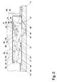
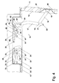
- the door 10 is in the region of its upper edge with a in the FIGS. 2 to 5 provided mounting mechanism 14 shown in detail, which dampens the closing movement of the door leaf shortly before reaching the end position or closed position and secures the closed position and limits the opening movement and damps shortly before reaching the ⁇ réellesend too.
- the mounting mechanism 14 includes a mounting housing 15, which in a corresponding recess of the door frame 13, d. H. is inserted in the upper leg.
- the mounting mechanism 14 is connected to the door leaf 12 via a scissor lever arrangement consisting of a first lever element 17 and a second lever element 16.
- a pivot bearing 18 is provided for the second lever element 16 on the inside of the door leaf 12.
- the pivot bearing 18 on the door leaf 12 is formed on a bearing housing 37 inserted into a recess 36 of the door leaf 12.
- the first lever element 17, which is connected via a hinge 19 with the second lever element 16, in turn, is pivotally mounted within the mounting housing 15 on a bearing axis 20.
- the first lever element 17 comprises at the in Fig. 4 the installation housing 15 side facing away from the joint 19 a lever extension 21, at the end of a trained as a roller or pin locking means 22 is arranged projecting in the vertical direction.
- the locking means 22 interacts with a first end position mechanism 23 associated with the closed position of the door leaf 12, which is arranged within the installation housing 15.
- first lever element 17 has, at the end facing away from the lever extension 21, a lever arm 24 which cooperates with a second end position mechanism 25 assigned to the open position of the door leaf 12, beyond the bearing axis 20.
- the first, the closed position associated end position mechanism 23 comprises a on a bearing axis 26 in a horizontal plane pivotally mounted claw bar 27 which is frontally formed with a recess 28 for engagement of the locking means 22.
- the claw bolt 27 On a fixed to a housing-fixed bearing axis 29 pivotally mounted, designed here as a gas spring actuator 30 is connected via a hinge point 31 which is formed on a lever portion 32.
- the claw bolt 27 is connected via a further pivot point 33 with a damping cylinder 34, which is also mounted fixed to the housing via a bearing axis 35 pivotally.
- the damping cylinder 34 may also be a gas spring, but the spring force is smaller than that of the actuating means forming gas spring 30.
- the force exerted by the damping cylinder 34 and the adjusting means 30 on the claw bolt forces are further characterized by the position of the pivot points 32 and 33 and resulting leverage determined.
- the locking means engages 22 shortly before reaching the closed position, in which the door leaf 12 bears against the door frame 13, in the recess 28 of the located in a first end position jaw bolt 27 a.
- the first end position of the jaw bolt 27 is defined by a stop formed by a front housing wall of the mounting housing 15. This first end position is secured by the force exerted by the gas spring 30 on the claw latch 27 torque.
- the second end position mechanism 25 of the installation mechanism 14 assigned to the open position comprises an end position damper 38, which is mounted pivotably on a pivot axis 39 and can be formed, for example, by a damping cylinder based on an oil pressure damping or by a gas pressure spring.
- a leg spring not shown here is provided, which the end position damper 38 in the in Fig. 2 shown biased end position, in which this rests with its housing on the rear wall of the mounting housing 15.
- the front end of a piston rod 40 has no contact with the lever arm 24 of the first lever member 17, that is, the piston rod 40 is exposed.
- the piston rod 40 has at its end a spherical end piece 41 which cooperates with a notch 42 which is formed on the lever arm 24 and may be provided to minimize noise when opening the door leaf 12 with a damping means such as felt or a non-woven on that hits the lever arm when opening the door leaf 12.
- a toggle mechanism 43 is furthermore provided, which comprises a first lever 44 mounted in the region of the bearing axis 20 and a second second lever 46 connected to the first lever 44 via a hinge 45, which in turn is mounted on an internally threaded bearing sleeve 47 by means of a hinge 48.
- the bearing sleeve 47 is seated on a threaded rod 49 which is rotatably mounted fixed to the housing via two saddles 50 and has a screw head 51 provided with an internal ram.
- the positioning of the bearing sleeve 47 on the threaded rod 49 can be done by engaging a Allen screwdriver in the screw head 51.
- the angle between the levers 44 and 46 of the knee lever mechanism 43 which forms a stop for a further notch 52 of the lever arm 24 of the lever element 17 in the region of the joint 45, changes.
- the position of this stop defines the maximum opening angle of the door leaf 12.
- the position of the stop without bearing sleeve and threaded rod can be adjusted.
- a fixable, the pivot axis for the lever 46 forming bolt is provided in the joint 48, which is slidably guided in a guideway or gate and can be jammed at a certain position.
- the damping cylinder 38 Shortly before the impact of the second notch 52 on the stop formed by the knee lever mechanism 43, the first notch 42 hits the spherical end piece 41 of the piston rod 40, which is then moved attenuated into the housing of the damping cylinder 38 during further pivoting of the door leaf 12. In this case, the damping cylinder 38 also experiences a pivoting movement about the pivot axis 39.
- FIGS. 6 to 9 illustrated embodiment of a mounting mechanism substantially corresponds to those of the FIGS. 2 to 5 but differs from this in that it has an end position lock for the open position of the door leaf 14.
- the end position lock comprises on the lever 44 'of the toggle mechanism 43' a latching recess 55 for a spring-loaded, frontally bevelled latching pin 56 which is slidably and captively stored in a groove 57 of the first lever member 17.
- a leg spring 59 is arranged in a substantially C-shaped cavity 58 of the lever member 17 constructed, for example, two-shell, which is also formed substantially C-shaped.
- the bias of the leg spring 59, ie the Andruck of a pressure piece performing detent pin or pawl element 56 on the lever 44 is adjustable by means of a threaded pin 60 designed as a grub screw.
- the door leaf 12 can be pivoted in the direction of the closed position by applying a corresponding manual force against the force of the leg spring 59.
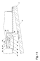
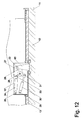
- FIGS. 10 to 12 is a further embodiment of a mounting mechanism according to the invention shown.
- This mounting mechanism comprises, contrary to the embodiments described above, only one of the closed position of the door leaf 12 associated Endlagenmechanik, which in turn corresponds to the Endlagenmechanik, in connection with the embodiment of the FIGS. 2 to 5 has been described.
- the embodiment according to the FIGS. 10 to 12 a locking pin or a locking roller 22 which is arranged on a bearing or projection 65, which in turn on the inside of the door leaf 14 is attached.
- the function and effect of the end position mechanism 23 corresponds to that in connection with the FIGS. 2 to 5 the closed position associated end position mechanism.
- the end position mechanism 23 has a housing 15 'adapted to its dimensions, which therefore requires a considerably smaller installation space compared to that according to the exemplary embodiments described above.
Landscapes
- Engineering & Computer Science (AREA)
- Mechanical Engineering (AREA)
- Closing And Opening Devices For Wings, And Checks For Wings (AREA)
Priority Applications (1)
| Application Number | Priority Date | Filing Date | Title |
|---|---|---|---|
| EP07020237A EP2050908A1 (fr) | 2007-10-16 | 2007-10-16 | Mécanisme integré |
Applications Claiming Priority (1)
| Application Number | Priority Date | Filing Date | Title |
|---|---|---|---|
| EP07020237A EP2050908A1 (fr) | 2007-10-16 | 2007-10-16 | Mécanisme integré |
Publications (1)
| Publication Number | Publication Date |
|---|---|
| EP2050908A1 true EP2050908A1 (fr) | 2009-04-22 |
Family
ID=38983787
Family Applications (1)
| Application Number | Title | Priority Date | Filing Date |
|---|---|---|---|
| EP07020237A Withdrawn EP2050908A1 (fr) | 2007-10-16 | 2007-10-16 | Mécanisme integré |
Country Status (1)
| Country | Link |
|---|---|
| EP (1) | EP2050908A1 (fr) |
Cited By (10)
| Publication number | Priority date | Publication date | Assignee | Title |
|---|---|---|---|---|
| WO2013017292A1 (fr) * | 2011-07-29 | 2013-02-07 | Helmut Fischer GmbH Institut für Elektronik und Messtechnik | Cale-porte, en particulier cale-porte pour porte coupe-feu |
| CN105386672A (zh) * | 2015-10-20 | 2016-03-09 | 老肯医疗科技股份有限公司 | 一种具有防夹手功能的便盆清洗机的柜门开关机构 |
| DE102015113811A1 (de) * | 2015-08-20 | 2017-02-23 | Karl Simon Gmbh & Co. Kg | Verschluss für eine Tür, Schublade, Klappe oder dergleichen |
| EP2685040A3 (fr) * | 2012-07-10 | 2018-01-17 | HAUTAU GmbH | Composant précontraint et procédé de fonctionnement pour une fenêtre ou une porte-fenêtre |
| DE102015000514C5 (de) * | 2015-01-18 | 2019-11-14 | Assa Abloy Sicherheitstechnik Gmbh | Türantriebseinrichtung mit Hauptantrieb und Hilfsantrieb |
| JP2020101059A (ja) * | 2018-12-25 | 2020-07-02 | マツ六株式会社 | 戸体の開閉機構 |
| CN113167090A (zh) * | 2018-11-30 | 2021-07-23 | 沙美卡尺和矿业灯具有限公司 | 用于向上打开柜门的家具铰链 |
| DE102015000516C5 (de) | 2015-01-18 | 2021-12-30 | Assa Abloy Sicherheitstechnik Gmbh | Türantriebseinrichtung mit Hauptantrieb und Hilfsantrieb |
| DE102015000513C5 (de) | 2015-01-18 | 2021-12-30 | Assa Abloy Sicherheitstechnik Gmbh | Türantriebseinrichtung mit Hauptantrieb und Hilfsantrieb |
| US20230399887A1 (en) * | 2020-10-28 | 2023-12-14 | Veranda Plus E.K. | Closure with valve device |
Citations (9)
| Publication number | Priority date | Publication date | Assignee | Title |
|---|---|---|---|---|
| DE243625C (de) * | 1911-04-04 | 1912-02-20 | Ferdertürschließer mit Hemmvorrichtung | |
| US2601983A (en) * | 1949-10-03 | 1952-07-01 | Louis F Schoelkopf | Door latching and starting apparatus |
| US3064847A (en) * | 1961-03-27 | 1962-11-20 | Nat Lock Co | Counter-balancing lid support |
| US3659886A (en) * | 1970-05-01 | 1972-05-02 | Sealth Aero Marine Co | Aircraft panels with precisely adjustable and easy action spring toggle latch |
| US4210349A (en) * | 1978-12-26 | 1980-07-01 | Standard Keil Hardware Manufacturing Co. | Device for holding a door firmly closed |
| EP0292610A1 (fr) * | 1987-05-28 | 1988-11-30 | Takaharu Watabe | Ferme-porte |
| US5749122A (en) * | 1995-06-07 | 1998-05-12 | Herbst; Walter B. | Interior door closer and method |
| DE10348436A1 (de) * | 2003-10-14 | 2005-06-02 | Dorma Gmbh + Co. Kg | Gestänge für einen Türschließer oder dergleichen |
| WO2007045631A1 (fr) * | 2005-10-18 | 2007-04-26 | Arturo Salice S.P.A. | Dispositif d'ouverture et de retenue d'une porte battante rotative |
-
2007
- 2007-10-16 EP EP07020237A patent/EP2050908A1/fr not_active Withdrawn
Patent Citations (9)
| Publication number | Priority date | Publication date | Assignee | Title |
|---|---|---|---|---|
| DE243625C (de) * | 1911-04-04 | 1912-02-20 | Ferdertürschließer mit Hemmvorrichtung | |
| US2601983A (en) * | 1949-10-03 | 1952-07-01 | Louis F Schoelkopf | Door latching and starting apparatus |
| US3064847A (en) * | 1961-03-27 | 1962-11-20 | Nat Lock Co | Counter-balancing lid support |
| US3659886A (en) * | 1970-05-01 | 1972-05-02 | Sealth Aero Marine Co | Aircraft panels with precisely adjustable and easy action spring toggle latch |
| US4210349A (en) * | 1978-12-26 | 1980-07-01 | Standard Keil Hardware Manufacturing Co. | Device for holding a door firmly closed |
| EP0292610A1 (fr) * | 1987-05-28 | 1988-11-30 | Takaharu Watabe | Ferme-porte |
| US5749122A (en) * | 1995-06-07 | 1998-05-12 | Herbst; Walter B. | Interior door closer and method |
| DE10348436A1 (de) * | 2003-10-14 | 2005-06-02 | Dorma Gmbh + Co. Kg | Gestänge für einen Türschließer oder dergleichen |
| WO2007045631A1 (fr) * | 2005-10-18 | 2007-04-26 | Arturo Salice S.P.A. | Dispositif d'ouverture et de retenue d'une porte battante rotative |
Cited By (13)
| Publication number | Priority date | Publication date | Assignee | Title |
|---|---|---|---|---|
| WO2013017292A1 (fr) * | 2011-07-29 | 2013-02-07 | Helmut Fischer GmbH Institut für Elektronik und Messtechnik | Cale-porte, en particulier cale-porte pour porte coupe-feu |
| EP2685040A3 (fr) * | 2012-07-10 | 2018-01-17 | HAUTAU GmbH | Composant précontraint et procédé de fonctionnement pour une fenêtre ou une porte-fenêtre |
| DE102015000516C5 (de) | 2015-01-18 | 2021-12-30 | Assa Abloy Sicherheitstechnik Gmbh | Türantriebseinrichtung mit Hauptantrieb und Hilfsantrieb |
| DE102015000514C5 (de) * | 2015-01-18 | 2019-11-14 | Assa Abloy Sicherheitstechnik Gmbh | Türantriebseinrichtung mit Hauptantrieb und Hilfsantrieb |
| DE102015000513C5 (de) | 2015-01-18 | 2021-12-30 | Assa Abloy Sicherheitstechnik Gmbh | Türantriebseinrichtung mit Hauptantrieb und Hilfsantrieb |
| DE102015113811A1 (de) * | 2015-08-20 | 2017-02-23 | Karl Simon Gmbh & Co. Kg | Verschluss für eine Tür, Schublade, Klappe oder dergleichen |
| CN105386672A (zh) * | 2015-10-20 | 2016-03-09 | 老肯医疗科技股份有限公司 | 一种具有防夹手功能的便盆清洗机的柜门开关机构 |
| CN113167090A (zh) * | 2018-11-30 | 2021-07-23 | 沙美卡尺和矿业灯具有限公司 | 用于向上打开柜门的家具铰链 |
| CN113167090B (zh) * | 2018-11-30 | 2022-08-16 | 沙美卡尺和矿业灯具有限公司 | 用于向上打开柜门的家具铰链 |
| US11603693B2 (en) | 2018-11-30 | 2023-03-14 | Samet Kalip Ve Maden Esya San. Ve Tic. A.S. | Furniture hinge for upward-opening cabinet doors |
| JP2020101059A (ja) * | 2018-12-25 | 2020-07-02 | マツ六株式会社 | 戸体の開閉機構 |
| US20230399887A1 (en) * | 2020-10-28 | 2023-12-14 | Veranda Plus E.K. | Closure with valve device |
| US12421787B2 (en) * | 2020-10-28 | 2025-09-23 | Veranda Plus E.K. | Closure with valve device |
Similar Documents
| Publication | Publication Date | Title |
|---|---|---|
| EP2050908A1 (fr) | Mécanisme integré | |
| DE10333925B4 (de) | Möbelscharnier mit Öffnungsautomatik, insbesondere für Möbeltüren | |
| DE102008048994B4 (de) | Feststellvorrichtung für einen Flügel einer Tür | |
| DE202020100939U1 (de) | Verdeckttürband mit Schließfunktion | |
| EP2094924A2 (fr) | Serrure pour portes d'aéronefs, en particulier d'hélicoptères | |
| DE102015000452A1 (de) | Vorrichtung zur Unterstützung und Erleichterung des Öffnens und Schließens für ein Fenster oder eine Tür | |
| DE102015000453A1 (de) | Vorrichtung zur Unterstützung und Erleichterung des Öffnens und Schließens sowie mit einer Einrichtung zur Regulierung für ein Fenster oder eine Tür | |
| DE102016202377A1 (de) | Beschlaganordnung zur Anbindung eines schieb- und kippbaren Flügels | |
| EP2169160B1 (fr) | Dispositif de fixation pour un battant de porte | |
| WO2016037862A1 (fr) | Système de ferrure | |
| DE1194732B (de) | Betaetigungsvorrichtung fuer Kipp-Schwenkfluegel von Fenstern, Tueren od. dgl. | |
| DE102011085177A1 (de) | Antriebssystem für ein KFZ-Dachsystem | |
| EP2157267A1 (fr) | Porte dotée d'un mécanisme intégré | |
| DE19902579C2 (de) | Verschlußvorrichtung für den unterschlagenden Flügel zweiflügeliger setzholzloser Fenster oder Türen | |
| DE202013100103U1 (de) | Kippbeschlag für einen Fenster- oder Türflügel | |
| DE20102570U1 (de) | Drehkippbeschlag | |
| DE2443036C3 (de) | Ausstellvorrichtung | |
| EP2511463B1 (fr) | Fenêtre, porte ou analogue pourvue d'un dispositif d'amortissement | |
| DE69205695T2 (de) | Flügelgelenkband für eine Tür, ein Fenster oder dergleichen von dem der Flügel nach aussen und um eine senkrechte Achse schwenkt gegenüber einem Fensterrahmen. | |
| DE102007007519A1 (de) | Schließautomat für einen Tür- oder Fensterflügel | |
| WO2007087945A1 (fr) | Ensemble charnière permettant une liaison par l'intermédiaire d'une articulation à charnière | |
| EP3626918B1 (fr) | Ferrure pour une fenêtre, fenêtre | |
| EP1612358A1 (fr) | Coordinateur de fermeture de portes à double battants | |
| EP3382130B1 (fr) | Dispositif de verrouillage et fenêtre ou porte avec un tel dispositif | |
| DE202017106974U1 (de) | Eine Scharnieranordnung mit einer Übertragungseinrichtung und einer Vorspanneinrichtung, sowie ein Dachfenster mit einer derartigen Scharnieranordnung |
Legal Events
| Date | Code | Title | Description |
|---|---|---|---|
| PUAI | Public reference made under article 153(3) epc to a published international application that has entered the european phase |
Free format text: ORIGINAL CODE: 0009012 |
|
| AK | Designated contracting states |
Kind code of ref document: A1 Designated state(s): AT BE BG CH CY CZ DE DK EE ES FI FR GB GR HU IE IS IT LI LT LU LV MC MT NL PL PT RO SE SI SK TR |
|
| AX | Request for extension of the european patent |
Extension state: AL BA HR MK RS |
|
| AKX | Designation fees paid | ||
| STAA | Information on the status of an ep patent application or granted ep patent |
Free format text: STATUS: THE APPLICATION IS DEEMED TO BE WITHDRAWN |
|
| 18D | Application deemed to be withdrawn |
Effective date: 20091023 |
|
| REG | Reference to a national code |
Ref country code: DE Ref legal event code: 8566 |